manuals.online logo
Brands
  1. Home
  2. •
  3. Brands
  4. •
  5. Geovent
  6. •
  7. Water Filtration System
  8. •
  9. Geovent GeoFilter GFO-XT Series User manual

Geovent GeoFilter GFO-XT Series User manual

GEOFILTER GFO-XT
Version 1.0 11/04 -2018
INSTRUCTION MANUAL
www.geovent.com
2
1.0 General safety precautions
IMPORTANT - Please study all the instructions
before installing and commissioning the lter.
Please keep manual for future reference.
Instruct all users in the function and operation of the
product.
Maintenance, replacement of lter cartridges should
only be done in accordance with section 4 in this
manual.
Power cables and pneumatic air hoses should be repla-
ced at once, if they are damaged. This should only be
done by trained electrician and ventilation tter.
Do not dismantle any factory-mounted parts, since it
impedes the commissioning of the equipment.
All electrical installations must be carried out by an
authorised electrician.
1.1 Danger
It is dangerous to dismantle the lter while in operation.
When installing or servicing of the lter make sure that
the power is disconnected.
1.2 Field of application
GeoFilter GFO-XT is used for ltration of oil saturated air
or fumes from polluting industrial processes such as ma-
chining, cutting and metal working involving cutting oil.
The GeoFilter GFO-XT comes with lter cartridges of
di󰀨erent pleated textiles with or without coating
(minimum ltration e󰀩ciency of 99,90% according to
BIA-test - see section 1.3.)
1.3 Technical data
Model No. of
cartridges Filter area [m²] Max. Air ow
GFO-XT-3 3 14,7 m² 1.800 m³/h
GFO-XT-6 6 29,4 m² 3.600 m³/h
GFO-XT-9 9 44,1 m² 5.400 m³/h
GFO-XT-12 12 58,8 m² 7.200 m³/h
Model Dimensions
(HxBxD) mm.
Inlet Outlet
GFO-XT-3 2032x325x927 Ø250mm Ø250mm
GFO-XT-6 2032x625x927 Ø315mm Ø315mm
GFO-XT-9 2032x925x927 Ø400mm 2xØ315mm
GFO-XT-12 2032x1225x927 Ø500mm 3xØ315mm
Temperature surroundings -10°C - +65°C
Relative humidity must be below <90%
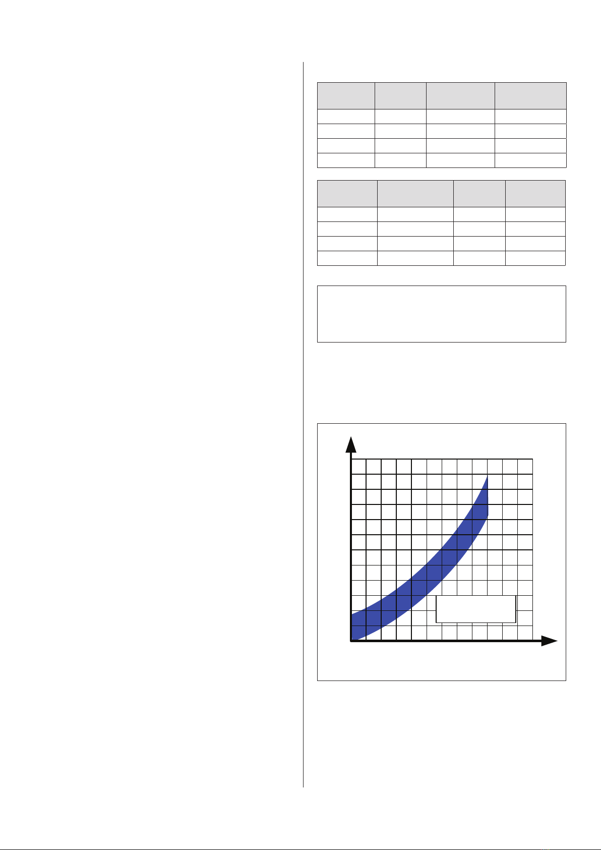
The pressure drop in the lter will vary depending on
the load and how dirty the lter cartridges are. The lter
cartridges must be replaced, when the pressure drop
exceeds 1.200 Pa.
Table of content
1.0 General safety precautions.................. 2
1.1 Danger ................................. 2
1.2 Field of application . . . . . . . . . . . . . . . . . . . . . . . . 2
1.3 Technical data............................ 2
1.4 Construction ............................. 2
2.0 Installation. .............................. 3
2.2 Test Run - adjusting ....................... 3
3.0 User instruction........................... 3
4.0 Maintenance............................. 3
4.1 Replacing lter cartridges................... 3
4.2 Trouble shooting ......................... 4
6.0 Declaration of conformity ................... 4
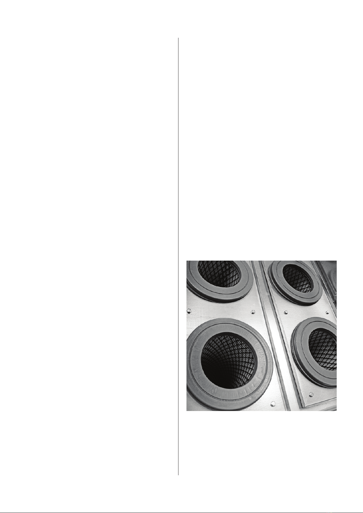
1.4 Construction
Cabinet: Sturdy frame/cabinet, made of galvanised
steel plate (corrosion class lll), with lter cone and
deector in the inlet.
150
400
Airflow [m³/h]
Pressure drop [Pa]
800 1200
300
450
600
750
900
1050
1200
1350
1500
1650
GFO filter
200 600 1000 1400 1600 1800 2000 2200
Lower curve = clean filter
Upper curve = dirty filter
3
2.0 Installation
To avoid condensation problems the lter should be
installed inside. However, if this is not possible, it can
be placed under a protection roof and the surrounding
temperature does go below minus 12°C. make sure to
use clean and dry air.
Consider the optimum installation area before
installation. Is placement of the lter inside possible?
Is there enough room for installation and service of
GFO-XT lter? Is there optimal connectivity for piping?
Make sure that there is su󰀩cient ground clearance, so
you can disconnect GFO-XT lter lid when replacing
the lter cartridge. At the bottom of GFO-XT lter there
must be room for the lter to drain the oil from the
mounted tank drain tap.
Procedure:
1. GFO-XT lter is inserted in the vertical duct system
or console
2. GeoFilter GFO XT is to be connected to a circular
spiral ventilation duct (SPIRO) on both clean and dirty
side. (The lower pipe connection is always dirty side).
Remember to seal the connection with joint compound
and/or tape!
3. To ensure the free ow of air, the return should be
two meters above the ridge of the roof with an air
velocity rate of at least 8 m/s.
2.2 Test Run - adjusting
We recommend you ensure the ventilation system sup-
plies the air ow, the system is dimensioned for.
Measure the airow and adjust using adjustment dam-
per. In case of overcapacity the power consumption
(amps) may exceed the capacity of the motor of the fan
which may cause the motor to overheat and eventually
fail.
3.0 User instruction
When the lter has been mounted and properly instal-
led, ready to use, there will be no interaction between
user and lter. Of course, the user must be aware of is
the correct ow in the system.
After max 8 hours of operation followed by min. 8 hours
rest.
4.0 Maintenance
A qualied technician should inspect the entire exhaust
ventilation system - at least once a year.
Periodic maintenance:
• Check pressure drop across lter and replace
lter cartridges, if this exceeds 1.200 Pa.
• Check the lter’s clean side of oil periodically and
replace lter cartridges in case of leaks.
• Empty the lter reservoir of oil using the drain
tap at the bottom.
4.1. Replacing lter cartridges
1. It is important that the service technician is
wearing the appropriate personal safety
precautions as prescribed by the Danish Working
Environment Authority. This must be in place before
removing the top of the lter.
2. Loosen the bolts holding the lid in place.
3. Lift the lidtop of to gain access to the top plate in
which the lter cartridge is mounted.
4. Loosen the plate holding the lter cartridges in
place and remove the cartridges.
5. Place the contaminated lter cartridges in a plastic
bag,which is sealed and disposed of according to
local regulations for disposal of oil and chemical
waste.
6. Install the new lter cartridge on the top plate
and secure it with the top plate and close lid.
4
4.2 Trouble shooting
Problem: The lter does not absorb oil from saturated,
polluted air, as it is supposed to.
Possible solution:
Check if the lter cartridge is correctly oriented. Filter
cartridge opening should be facing up.
Problem: Insu󰀩cient airow.
Possible solution:
Check if replacement of the lter cartridge
needs replacement.
Replace the lter cartridge, if that is the case.
Problem: Noise from the lter.
Possible solution:
Check if the lter cartridge is properly
secured to the top plate. Secure the lter
cartridge.
Problem: Oil in the lter reservoir does not bleed.
Possible solution:
Check if grinding dust or metal shavings blocks the
drain tap.
Clean, if this is the case.
5.0 Liability
Warranty:
Geovent A/S grants a warranty for products, which are
defective, when it can be proved that the defects are
due to poor manufacture or materials on the part of
Geovent.
The warranty comprises remedial action (repair or
exchange) until one year after the date of shipment.
No claims can be made against Geovent A/S in relation
to loss of earnings or consequential loss because of
defects on products from Geovent.
Wear parts as fan wheels and hoses are not included in
the warranty.
User liability:
In order for Geovent to grant the declared warranty, the
user/tter must follow this Instruction manual in all
respects.
Under no circumstances may the products be altered
in any way without prior, written consent from Geovent
A/S.
Moreover, we refer to the current terms of sale and
delivery at www.geovent.com.
HOVEDGADEN 86 • DK-8831 LØGSTRUP
(+45) 8664 2211 • [email protected]
Date: May 11th -2018
Position: Managing director
Name: Thomas Molsen
Signature : ____________________________
6.0 Declaration of conformity
The manufacturer: GEOVENT A/S
HOVEDGADEN 86
DK-8831 LØGSTRUP
hereby declares that:
The product: GFO-XT lter
Model: GFO-XT-3, GFO-XT-6,
GFO-XT-9,GFO-XT-12
has been manufactured in compliance with the
following directives and standars:
European Parliament and Council Directive 2006/42/
EC of 17 May 2006 on machinery, and amendments to
Directive 95/16/EC.
EN ISO 14121-1:2007 Risk assessment – part 1
EN ISO 12100-1:2005 Basic concepts and general
principles for design.
EN ISO 12100-1:2009 construction and design
Part 1: Basic terminology and
methodology
EN ISO 12100-2:2005 Basic concepts and general
principles for design.
EN ISO 12100-2:2009 Construction and design
Part 2: Technical principles
WWW.GEOVENT.COM

This manual suits for next models

4

Other Geovent Water Filtration System manuals

Geovent GEOFILTER GFO 315 User manual

Geovent

Geovent GEOFILTER GFO 315 User manual

Geovent GEOGO User manual

Geovent

Geovent GEOGO User manual

Geovent W 3 User manual

Geovent

Geovent W 3 User manual

Geovent GF 315 User manual

Geovent

Geovent GF 315 User manual

Geovent GEOFILTER GFB2 W3 User manual

Geovent

Geovent GEOFILTER GFB2 W3 User manual

Geovent Dustbox CFU-1000 User manual

Geovent

Geovent Dustbox CFU-1000 User manual

Popular Water Filtration System manuals by other brands

Brita On Line Active Instructions for use

Brita

Brita On Line Active Instructions for use

SE Electronics REFLEXION FILTER PRO Assembly & use instructions

SE Electronics

SE Electronics REFLEXION FILTER PRO Assembly & use instructions

Grundfos AQpure instructions

Grundfos

Grundfos AQpure instructions

SBIG CFW-9 manual

SBIG

SBIG CFW-9 manual

Green DW 10 manual

Green

Green DW 10 manual

DeWalt DXCM019-0342 manual

DeWalt

DeWalt DXCM019-0342 manual

Neptun Premium NPTF-O 15000 operating instructions

Neptun Premium

Neptun Premium NPTF-O 15000 operating instructions

Costguard CGS-20 Installation and operation guide

Costguard

Costguard CGS-20 Installation and operation guide

Aqua Science Fleck 5600 SXT installation manual

Aqua Science

Aqua Science Fleck 5600 SXT installation manual

GE GQSL55F Owner's manual and installation instructions

GE

GE GQSL55F Owner's manual and installation instructions

Bestway FLOWCLEAR 58404 owner's manual

Bestway

Bestway FLOWCLEAR 58404 owner's manual

Argo-Hytos FNA1 008 manual

Argo-Hytos

Argo-Hytos FNA1 008 manual

Clean Water Systems 7500-M installation guide

Clean Water Systems

Clean Water Systems 7500-M installation guide

BUON VINO MINIJET quick start guide

BUON VINO

BUON VINO MINIJET quick start guide

Lenze EZN3 0110H030 Series Mounting instructions

Lenze

Lenze EZN3 0110H030 Series Mounting instructions

NatureWater NW-1000 Operation manual

NatureWater

NatureWater NW-1000 Operation manual

GRE AR119 Installation and maintenance manual

GRE

GRE AR119 Installation and maintenance manual

Ingersoll-Rand GP19 instruction manual

Ingersoll-Rand

Ingersoll-Rand GP19 instruction manual

manuals.online logo
manuals.online logoBrands
  • About & Mission
  • Contact us
  • Privacy Policy
  • Terms and Conditions

Copyright 2025 Manuals.Online. All Rights Reserved.