GeoVision GV-QFER12700 User manual

Before attempting to connect or operate this product,
please read these instructions carefully and save this manual for future use.
User's Manual
GV-QFER12700
QFER-UM-B

© 2022GeoVision, Inc. All rights reserved.
Under the copyright laws, this manual may not be copied, inwhole or inpart,
without the written consent of GeoVision.
Every effort has been made to ensure that the information in this manual is
accurate. GeoVision, Inc. makes no expressed or implied warranty of any kind
and assumes no responsibility for errors or omissions. No liability is assumed
for incidental or consequential damages arising from the use of the information
or products contained herein. Features and specifications are subject to
change without notice.
GeoVision, Inc.
9F, No. 246, Sec. 1, Neihu Rd.,
Neihu District, Taipei, Taiwan
Tel: +886-2-8797-8377
Fax: +886-2-8797-8335
http://www.geovision.com.tw
Trademarks used in this manual: GeoVision, the GeoVision logo and GV
series products are trademarks of GeoVision, Inc. Windows is the registered
trademark of Microsoft Corporation.
October 2022
Scan the following QR codes for product warranty and technical support
policy:
[Warranty] [Technical Support Policy]

1
Preface
Welcome to the GV-QFER12700 User’s Manual.
This Manual provides an overview of GV-QFER12700 and its accessories. The
instructions herein will guide you through the installation and use of GV-
QFER12700.
Note: GV-QFER12700 can be installed to the wall or ceiling with GV-Mount206-1 / 903-2 /
904-2 / 912-1 / 919. Refer to the following sections and documents.
GV-Mount 206-1 (5.4.2 GV-FER5701 / FER12203 / FER12700 / EFER3700 / EFER3700-W
/ QFER12700, GV-Mount Accessories Installation Guide)
GV-Mount903-2 (5.1.2 GV-EFER3700 / GV-EFER3700-W / GV-QFER12700, GV-Mount
Accessories Installation Guide)
GV-Mount904-2 (5.6.2 GV-Mount904-1, GV-Mount Accessories Installation Guide)
GV-Mount912-1 (5.12 Power Box Mount, GV-Mount Accessories Installation Guide)
GV-Mount919 (Appendix C: In-Ceiling Mount Installation, GV-QFER12700 User’s Manual)

2
Table of Contents
Regulatory Notices ..........................................................................................................................3
Note for Connecting to GV-VMS / DVR / NVR.................................................................................4
Note for Recording ..........................................................................................................................4
Optional Devices..............................................................................................................................5
1.Overview....................................................................................................................................6
2.Main Tabs ..................................................................................................................................7
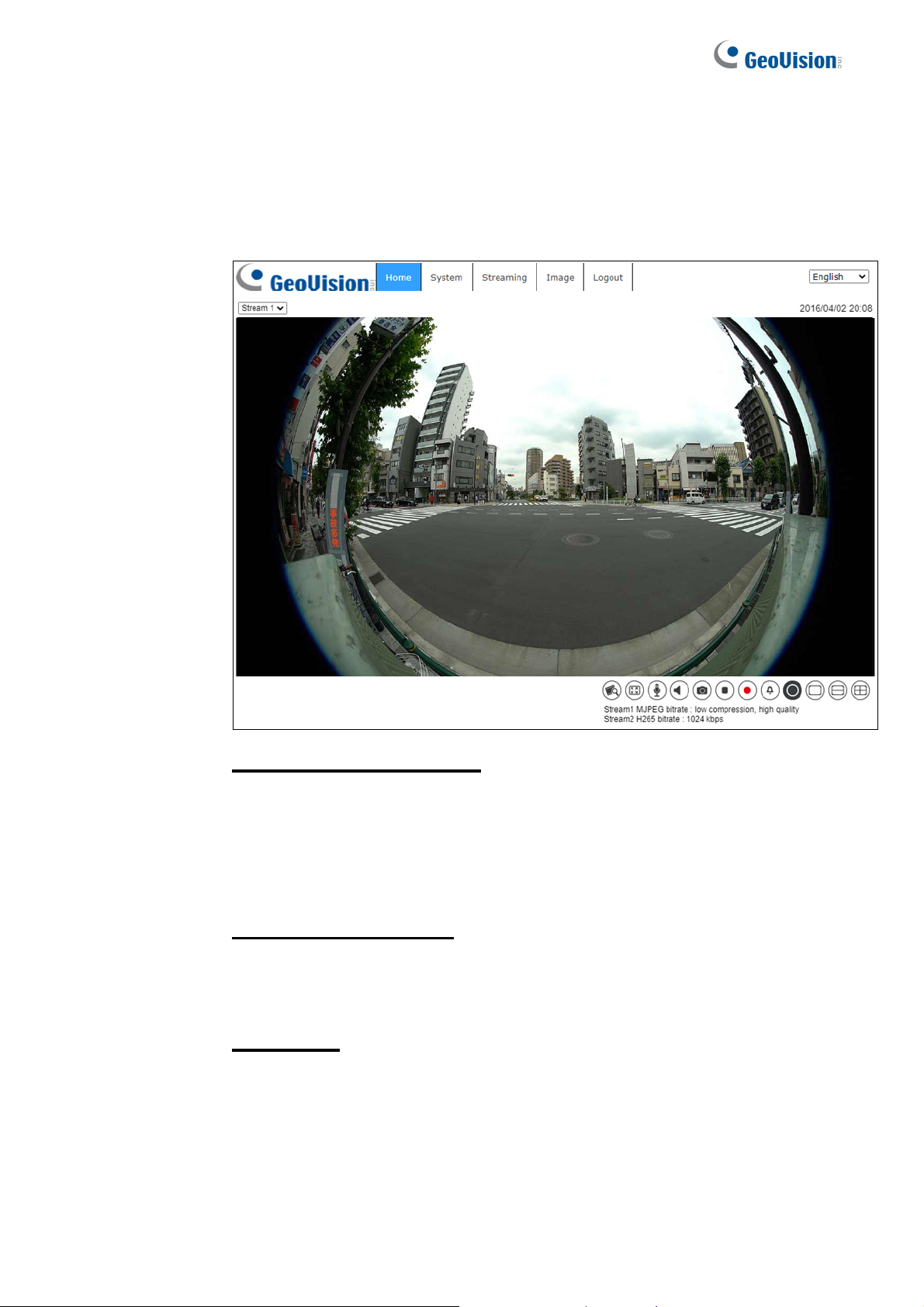
2.1Home Page ............................................................................................................... 8
2.2System .................................................................................................................... 11
2.2.1
System............................................................................................................................................................11
2.2.2
Security ......................................................................................................................................................... 13
2.2.3
Network......................................................................................................................................................... 21
2.2.4
DDNS............................................................................................................................................................ 28
2.2.5
Mail ............................................................................................................................................................... 28
2.2.6
FTP................................................................................................................................................................ 29
2.2.7
HTTP............................................................................................................................................................. 29
2.2.8
Events (Alarm Settings) ................................................................................................................................. 30
2.2.9
StorageManagement ..................................................................................................................................... 57
2.2.10
Recording...................................................................................................................................................... 61
2.2.11
Schedule........................................................................................................................................................ 62
2.2.12
File Location (Snapshots and Web Recording) .............................................................................................. 63
2.2.13
View Information........................................................................................................................................... 64
2.2.14
FactoryDefault .............................................................................................................................................. 65
2.2.15
SoftwareVersion (Firmware Version)............................................................................................................ 65
2.2.16
SoftwareUpgrade (Firmware Upgrade) ........................................................................................................ 66
2.2.17
Maintenance .................................................................................................................................................. 67
2.3Streaming ............................................................................................................... 68
2.3.1
Video Configuration (Video Format & Resolution) ....................................................................................... 69
2.3.2
Video Rotation............................................................................................................................................... 71
2.3.3
Video Text Overlay........................................................................................................................................ 72
2.3.4
Video ROI Encoding ..................................................................................................................................... 74
2.3.5
Video OCX Protocol...................................................................................................................................... 74
2.3.6
Video Mask ................................................................................................................................................... 75
2.3.7
Audio (Audio Mode and Bit Rate Settings).................................................................................................... 76
2.4Image ...................................................................................................................... 77
2.4.1
Exposure ....................................................................................................................................................... 78
2.4.2
White Balance................................................................................................................................................ 79
2.4.3
PictureAdjustment......................................................................................................................................... 81
2.4.4
Color Style .................................................................................................................................................... 82
2.4.5
IR Function.................................................................................................................................................... 83
2.4.6
Noise Reduction ............................................................................................................................................ 85
2.4.6
WDR Function............................................................................................................................................... 86
2.4.7
Backlight ....................................................................................................................................................... 86
2.4.8
Profile............................................................................................................................................................ 86
2.4.9
Fisheye Setting .............................................................................................................................................. 87
2.4.10
TV System..................................................................................................................................................... 89
2.5Logout..................................................................................................................... 89
Appendix A: Install UPnP Components ........................................................................................90
Appendix B: IP Addresses from Decimal to Binary .....................................................................91
Appendix C: In-Ceiling Mount Installation....................................................................................92
Appendix D: Dimensions...............................................................................................................94

3
Regulatory Notices
FCC Notice
This equipment has been tested and found to comply with the limits of a Class A digital
device, pursuant to part 15 of the FCC Rules. These limits are designed to provide
reasonable protection against harmful interference when the equipment is operated in a
commercial environment.
Class A
This equipment generates, uses, and can radiate radio frequency energy and, if not installed
and used in accordance with the instruction manual, may cause harmful interference to radio
communications. Operation of this equipment in a residential area is likely to cause harmful
interference in which case the users will be required to correct the interference at their own
expense.
CE Notice
This is a Class A product. In a domestic environment, this product may cause radio
interference in which case the users may be required to take adequate measures.
RoHS Compliance
The Restriction of Hazardous Substances (RoHS) Directive is to forbid the use of hazardous
materials for production. To meet the RoHS Directive requirements, this product is made to
be RoHS compliant.
WEEE Compliance
This product is subject to the Waste Electrical and Electronic Equipment (WEEE) Directive
and made compliant with the WEEE requirements.

4
Note for Connecting to GV-VMS / DVR / NVR
The GV-QFER12700 is designed to work with and record on GV-VMS / DVR / NVR, a video
management system.
Once the camera is connected to the GV-VMS / DVR / NVR, the resolution set on the GV-
VMS / DVR / NVR will override the resolution set on the camera’s Web interface. You can
only change the resolution settings through the Web interface when the connection to the
GV-VMS / DVR / NVR is interrupted.
Note: Currently, only GV-VMS, applied with the patches, supports GV-QFER12700.
Note for Recording
1. By default, the images are recorded to the memory card inserted in the GV-IP Seed
Dome.
2. Mind the following when using a memory card for recording:
Recorded data on the memory card can be damaged or lost if the data are accessed
while the camera is under physical shock, power interruption, memory card
detachment or when the memory card reaches the end of its lifespan. No guarantee is
provided for such causes.
The stored data can be lost if the memory card is not accessed for a long period of
time. Back up your data periodically if you seldom access the memory card.
Memory cards are expendable and their durability varies according to the conditions
of the installed site and how they are used. Back up your data regularly and replace
the memory card annually.
To avoid power outage, it is highly recommended to apply a battery backup (UPS).
For better performance, it is highly recommended to use Micro SD card of MLC NAND
flash, Class 10.
Replace the memory card when its read/write speed is lower than 6 MB/s or when the
memory card is frequently undetected by the camera.
3. To ensure smooth network usage, do not access the live view from more than 20
connections.

5
Optional Devices
Optional devices can expand the capabilities and versatility of your GV-QFER12700. Contact
your dealer for more information.
Device Description
GV-Mount Accessories
The GV-Mount Accessories provide a comprehensive
lineup of accessories for installing the GV-QFER12700
on the ceiling or wall. For details, refer to Appendix C:
In-Ceiling Mount Installation, GV-QFER12700 User’s
Manual or GV-Mount Accessories Installation Guide.
GV-PoE Power Adapter
GV-PoE Adapter is designed to provide power to the
IP device through a single Ethernet cable. Adopting
the PoE adapter enables you to mount an IP device
anywhere in a building where power outlets are not
available.
GV-PoE Switch
The GV-POE Switch is designed to provide power
along with network connection for IP devices. The GV-
POE Switch is available in various models with
different types and numbers of ports.
Power Adapter Contact our sales representatives for the countries
and areas supported.

Overview
6
1
1. Overview
GV-QFER12700 is a high-performance surveillance solution and features 360°
wide coverage without blind spots. The fisheye camera supports up to 12
Megapixels resolution streaming and maintains at 20 fps that allows the video
stream can be viewed smoothly. Moreover, the fisheye camera supports various
view mode (digital PTZ, panoramic view, etc.) which allows users to choose
based on their own preference. GV-QFER12700 is suitable to apply in wide
open space environments like office rooms, hotel lobby, apartment front door,
etc.
In addition, the embedded edge dewarping engine enables the camera to
dewarp images by the camera itself rather than consuming resources from the
backend devices. The camera also includes IR LED module and Smart
Picture/Quality/Noise Reduction features that improves the image quality in low
light environment.

Main Tabs
7
2
2. Main Tabs
There are six setting tabs, including <Home>, <System>, <Streaming>,
<Camera>, <PTZ> and <Logout> on the Home Page.
Home
Users can monitor the live video of the targeted area.
System Setting
The administrator can set system time, root password, network related
settings, etc. Further details will be interpreted in chapter System.
Streaming Setting
The administrator can configure video format, video compression, video OCX
protocol, video frame rate and audio compression in this page.
Image Setting
This setting page is only available for the administrator and user accounts that
have been granted the privilege of camera control. The administrator and users
can adjust various camera parameters including Exposure, White Balance,
Picture Adjustment, Color Style, IR Function, Digital Zoom, WDR, etc.
Logout
Click the tab to re-login the camera with another username and password.

8
2.1 Home Page
Click the tab <Home> to access the <Home> Page. There are several
function buttons on this page. See the detailed information of each
item below.
Multiple Languages Support
Multiple languages are supported, including Czech, English, French,
German, Hungarian, Italian, Japanese, Portuguese, Russian, Spanish,
Traditional Chinese, and Simplified Chinese for the viewer window
interface.
Display Stream Selection
According to the streaming setting, users can choose the one stream to
display from the drop-down list.
Camera Info
Double click the live view pane, and the camera info window will pop up.
Users can instantaneously check the basic information of the
camera, such as IP address, network status, video format, etc.

Main Tabs
9
2
Video Quality
Click to show/hide bitrate and compression of each stream.
Full Screen
Image display size can be adjusted to full screen. Alternatively, right click the
Live Video Pane and select <Fullscreen> to go full screen.
To exit full screen mode, users can (1) tap <Esc> on the keyboard; (2) double
click the Live Video Pane; (3) right click the Live Video Pane and select
<Normal view>.
Talk (On / Off)
Talk function allows the local site talks to the remote site. Click the button to
switch it to On / Off. Users must select the suitable transmission mode under this
path: Streaming> Audio to enable this function.
NOTE: This function is only available for user accounts that have been
granted this privilege by the administrator. Please refer to Security: Add
user> Talk/Listen for further details.
Listen (On / Off)
Click the <Listen> button to mute / activate the audio. Users must select the
suitable transmission mode under <Streaming> Audio to enable this function.
NOTE: This function is only available for user accounts that have been
granted this privilege by the administrator. Please refer to Security:
Add user> Talk/Listen for further details.
Snapshot
Click the button and the JPEG snapshots will automatically be saved in the
appointed place: C:\ProgramData\Geovision\. To change the storage
location, please refer to section File Location of the next chapter for further
details.
NOTE: With Windows 7 operating system or above, to implement the
Snapshot function, users must run IE as administrator. To run IE as
administrator, right click the IE browser icon and select “Run As
Administrator” to launch IE.

10
Live View Pause / Restart (Pause / Restart)
Click < > to disable video streaming, the live video will be displayed as black.
Press < > to show the live video.
Record (O
n / Off)
Click the <Record> button and the Live View through the web browsing will be
directly recorded to the specific location on the local hard drive, which could be
configured in the <File Location> page. The default storage location for the
web recording is: C:\ProgramData\Geovision\. Please refer to section File
Location of the next chapter for further details.
NOTE: With Windows 7 operating system or above, to implement the
Web Recording function, users must run IE as administrator. To run IE
as administrator, right click the IE browser icon and select “Run As
Administrator” to launch IE.
Manual Trigger (On / Off)
Click the <Manual Trigger > button to turn on and off the manual trigger. Please
refer to section Manual Trigger of the next chapter for further details.
Fisheye Image Adjustment
Pan/Tilt Control
Users can implement pan/tilt control by moving the cursor to the live video
pane, then left click and drag the pointer in any direction.
Optical Zoom Control
In Full Screen display mode, users can implement zoom in / out by
scrolling up/down the mouse wheel.

Main Tabs
11
2
2.2 System
Under the tab <System>, the categories are shown as the configure page
below.
NOTE: The <System> configuration page is only accessible by the
administrator.
2.2.1
System
The System setting can be found under the path: System > System.
Time Zone
Select the time zone from the drop-down menu according to the location of the
camera.
Enable Daylight Saving Time
To enable DST, please check the item and then specify the time offset and the
DST duration. The format for time offset is [hh:mm:ss]; for instance, if the
amount of time offset is one hour, please enter “01:00:00” into the field.

12
Time format
Choose a time format (yyyy/mm/dd or dd/mm/yyyy) from the drop-down menu.
The format of the date and time displayed above the live video window will be
changed according to the selected format.
Sync with Computer Time
Select the item, and video date and time display will synchronize with the PC’s.
NOTE: Users MUST click the <Save> button to confirm the setting.
Otherwise, the time will not be synced.
Manual
The administrator can set video date and time manually. Entry format should be
identical with the examples shown next to the enter fields.
Sync with NTP Server
Network Time Protocol (NTP) is an alternate way to synchronize the camera’s
clock with a NTP server. Please specify the server that is wished to synchronize
in the entry field. Then select an update interval from the drop-down menu.
For further information about NTP, please see the web site: www.ntp.org.
NOTE: The synchronization will be done every time the camera boots
up.
Click the <Save> button to confirm the setting.

Main Tabs
13
2
2.2.2
Security
The Security setting can be found under this path: System> Security.
Click the <Security> category, there will be a drop-down menu with tabs
including <User>, <HTTPS>, <IP Filter>, and <IEEE 802.1X>.
2.2.2.1 User
The User setting can be found under this path: System> Security> User.
Admin Password
This item is for the administrator to reset password. Enter the new password in
<Admin password> and <Confirm password>. The maximum length is 14
characters. The input characters / numbers will be displayed as dots for security
purposes. Click the <Save> button to confirm the changes. After the changes
are confirmed, the web browser will ask the administrator to re-login to the
camera with the new password.
NOTE: The following characters are valid: A-Z, a-z, 0-9, !#$%&’-.@^_~.
Add User
This item is for the administrator to add new users. Enter the new user’s name
in <User name> and the password in <User password>. Username can be up to
16 characters, and the maximum length of the password is 14 characters. Tick
the boxes below to give privileges for functions, including “Camera control”,
“Talk” and “Listen”. Click the <Add> button to add the new user. The name of
the new added user will be displayed in the <User name> drop-down list under
<Manage User>. There is a maximum of twenty user accounts.
I/O access
This item supports fundamental functions that enable users to view the
live video when accessing to the camera.
Camera control
This item allows the appointed user to change camera parameters on
the <Camera> and <PTZ> setting page.

14
Talk/Listen
This item allows the appointed user in the local site (PC site) to
communicate with, for instance, the administrator in the remote site.
Manage User
Delete user
Pull down the <User name> drop-down list and select the username that
is wished to be deleted. Click the <Delete> button to remove the
selected name.
Edit user
Pull down the <User name> drop-down list and select the username.
Click the <Edit> button and a popup window will appear. In the appeared
window, enter the new user password and reset the privileges. Click the
<Save> button to confirm the changes. Then click the <Close> button to
complete the editing.
HTTP Authentication Setting
This setting allows secured connections between the IP camera and web
browser by enforcing access controls to web resources. When users approach
to the web browser, it’ll ask for username and password, which protects the
camera settings or live streaming information from snooping. There are two
security models available: Basic and Digest. Refer to the descriptions below for
more details.
Basic
This mode can only provide basic protection for the connection security.
There will still be risks for the password being intercepted.
Digest
Digest mode is a safer option for protection. The password is sent in an
encrypted format to prevent it from being stolen.
NOTE: Users MUST click the <Save> button to apply the setting.

Main Tabs
15
2
Streaming Authentication Setting
This setting provides security against unauthorized users from getting streaming
via Real Time Streaming Protocol (RTSP). If the setting is enabled, users will be
requested to enter user name and password before viewing the live streams.
There are three security modes available: Disable, Basic and Digest. Refer to
the descriptions below for more details.
Disable
If disable mode is selected, there will be no security provided to against
unauthorized access. Users will not be asked to input user name and
password for authentication.
Basic
This mode can only provide basic protection for the live streams.
There will still be risks for the password being intercepted.
Digest
Digest mode is a safer option for protection. The password is sent in an
encrypted format to prevent it from being stolen.
NOTE: Users MUST click the <Save> button to apply the setting.
Enable Account Lockout Function
This setting provides extra security against unauthorized users who intend to log
in by guessing the username or password. If the setting is enabled, login will not
be allowed for the set duration once the maximum login failure is reached.
Threshold
Set the maximum number of login failure.
Duration
Set the duration for account lockout.
NOTE: Users MUST click the <Save> button to apply the setting.

16
2.2.2.2 HTTPS
The HTTPS setting can be found under this path: System> Security> HTTPS.
<HTTPS> allows secure connections between the camera and the web browser
using <Secure Socket Layer (SSL)> or <Transport Layer Security (TLS)>, which
ensure camera settings or Username / Password info from snooping. It is
required to install a self-signed certificate or a CA-signed certificate for
implementing HTTPS.
To use HTTPS on the camera, an HTTPS certificate must be installed. The
HTTPS certificate can be obtained by either creating and sending a certificate
request to a Certificate Authority (CA) or creating a self-signed HTTPS
certificate, as described below.
Create Self-signed Certificate
Before a CA-issued certificate is obtained, users can create and install a self-
signed certificate first.
Click the <Create> button under “Create self-signed certificate” and provide the
requested information to install a self-signed certificate for the camera.
Please refer to the last part of this section Provide the Certificate Information for
more details.
NOTE: The self-signed certificate does not provide the same high level
of security as when using a CA-issued certificate.
Install Signed Certificate
Click the <Create Certificate Request> button to create and submit a certificate
request in order to obtain a signed certificate from CA.
Provide the request information in the create dialog. Please refer to the
following section Provide the Certificate Information for more details.
When the request is complete, the subject of the Created Request will be shown
in the field. Click the <Properties> button below the Subject field, copy the
PEM-formatted request and send it to the selected CA.
When the signed certificate is returned, install it by uploading the signed
certificate.

Main Tabs
17
2
Provide the Certificate Information
To create a Self-signed HTTPS Certificate or a Certificate Request to CA,
please enter the information as requested.
Create Self Signed Certificate Create Certificate Request
Country vv
State or Province vv
Locality vv
Organization vv
Organizational Unit vv
Common Name vv
Valid Days v-
Country
Enter a two-letter combination code to indicate the country the certificate
will be used in. For instance, type in “US” to indicate United States.
State or province
Enter the local administrative region.
Locality
Enter other geographical information.
Organization
Enter the name of the organization to which the entity identified in
“Common Name” belongs.
Organization Unit
Enter the name of the organizational unit to which the entity identified in
“Common Name” belongs.
Common Name
Indicate the name of the person or other entity that the certificate
identifies (often used to identify the website).
Valid days
Enter the period in days (1 to 9999) to indicate the valid period of
certificate.
Click the <OK> button to save the Certificate Information after completing the
setting.

18
2.2.2.3 IP Filter
The IP Filter setting can be found under this path: System> Security> IP Filter.
With IP Filter, users can allow or deny specific IP addresses from accessing the
camera.
Enable IP Filter
Check the box to enable the IP Filter function. Once enabled, the listed
IP addresses (IPv4) in the <Filtered IP Addresses> list box will be
allowed / denied to access the camera.
Select <Allow> or <Deny> from the drop-down list and click the <Apply>
button to determine the IP filter behavior.
Add IP Address
Input IP address at the blank space below the <Filtered IP Address> list
and click the <Add> button. The newly-added address will be shown in
the list. Up to 256 IP address entries can be specified.
In addition, to filter a group of IP addresses, enter an address at the
blank space followed with a slash and a number ranging from 1 to 31,
e.g. 192.168.2.81/30. The number after the slash can define how many
IP addresses will be filtered. For details, please refer to the following
example.
Example: Filtering a group of consecutive IP addresses
The steps below show what will be filtered when 192.168.2.81/30 is
entered.
Step 1: Convert 192.168.2.81 to binary numbers. The binary
numbers are 11000000.10101000.00000010.01010001. Users can
refer to Appendix B: IP Addresses from Decimal to Binary for
converting the IP addresses to binary numbers. The number “30”
after the slash is referring to the first 30 digits of the binary numbers.
Step 2: Convert a few IP addresses before and after 192.168.2.81
to binary numbers. Then compare their first 30 digits with the binary
numbers of 192.168.2.81.
Other manuals for GV-QFER12700
1
Table of contents
Other GeoVision Digital Camera manuals

GeoVision
GeoVision GV-IPCam H.264 Series Installation guide

GeoVision
GeoVision GV-BX120D series User manual

GeoVision
GeoVision GV-IP Decoder Box Series User manual

GeoVision
GeoVision GV-CR1320 User manual

GeoVision
GeoVision GV-CR420 User manual

GeoVision
GeoVision GV-PBL8800 User manual

GeoVision
GeoVision GV-PFER12800 User manual

GeoVision
GeoVision GV-BX110D User manual

GeoVision
GeoVision GV-IPCAM User manual

GeoVision
GeoVision GV-3D People Counter V2 User manual