La centralina funziona con
ingresso 4-20mA o 0-10V in base
a l c o l l e g a m e n t o e l e t t r i c o
effettuato.
E’ consigliata una sezione dei cavi
di almeno 0, mmq e una
lunghezza massima dei cavi di
segnale di 2 0mt, avendo cura di
separarne il percorso dai cavi di
potenza.
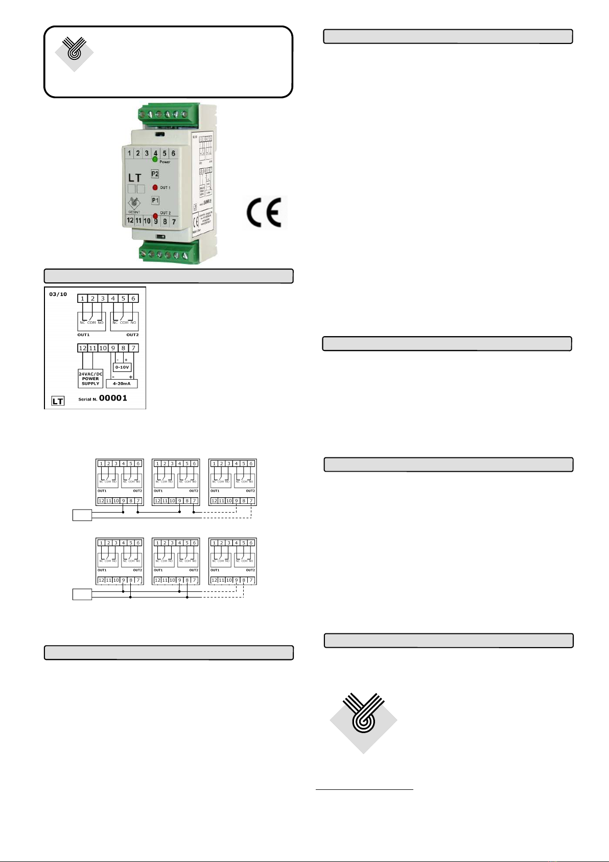
Nel caso l’applicazione richieda un numero di soglie
superiore a 2, è possibile collegare in serie (ingresso
corrente) o in parallelo (ingresso tensione) le centraline LT
secondo gli schemi seguenti:
E’ consigliabile verificare il carico massimo, se utilizzato
con ingresso in corrente, o il carico minimo,
se utilizzato con ingresso in tensione, supportabile
GESINT
GESINTGESINT
GESINT
®
®®
®
LT
Centralina a 2 soglie
di corrente o tensione regolabili
Alimentazione: 24VAC/DC (LT-A)
110-230VAC (LT-D)
Consumo: 2VA / 1,8W max
Segnale in ingresso: 4-20mA o 0-10V
Impedenza d’ingresso: Max 2 0Ω (mA) o Min 10KΩ (V)
Uscite: 2 contatti SPDT
Isteresi: 2% fissa
Portata contatto: 7A @ 2 0 VAC (carico resistivo)
3A @ 230 VAC (carico induttivo)
Modalità standard relè normalmente eccitati
Programmazione: tramite 2 pulsanti
Segnalazioni: LED Verde Alimentazione
LED Rosso Soglia
Protezione: IP20
Temp. di stoccaggio: da –30 a +80°C
Temp. di esercizio: da –20 a +60°C
Umidità relativa: da 0 a 8 % senza condensa
Montaggio: Barra DIN 3 mm
Connessioni elettriche: Morsettiere a vite estraibili
Dimensioni: 90(H) x 3 (L) x 60(P) mm
Marcatura CE in conformità alla Direttiva 89/336/CEE secondo le
Norme Armonizzate: EN50081-1, EN 50082-2, EN55022,
EN61000-4-2, EN61000-4-3, EN61000-4-4, EN61000-4-5,
EN61000-4-6, EN61000-4-11 e alla Direttiva Bassa Tensione
73/23/CEE e successive modifiche.
GESINT S.R.L.
Via Perosi,
20010 Bareggio (MI) - ITALY
Tel. 02/9014633 - 33 /628261
Fax 02/9036229
E-mail: info@gesintsrl.it
GESINT
GESINTGESINT
GESINT
®
®®
®
WWW.GESINTSRL.IT
Lo strumento è coperto da una garanzia di 12 mesi
dall’acquisto e decade se utilizzato in maniera impropria o non
correttamente installato sull’impianto.
LT è una centralina a 2 soglie regolabili con ingresso in
corrente 4-20mA o tensione 0-10V. Può quindi essere abbinata a
qualunque strumento dotato di uscita analogica in corrente o
tensione, tra cui: trasmettitori di pressione, convertitori per PT100,
amplificatori per sonde capacitive e misuratori di livello.
La regolazione delle soglie, i cui punti di intervento sono
indipendenti, avviene tramite gli appositi pulsanti di
programmazione. Al raggiungimento della soglia impostata
avviene la commutazione del relè di uscita e la segnalazione
visiva tramite il corrispondente LED di colore rosso.
Generale
Rimuovere la mascherina frontale dello strumento per poter
accedere ai 2 pulsanti di programmazione e collegare ai morsetti
di ingresso dello strumento il segnale analogico 4-20mA o 0-10V.
1) Premere il tasto P2 per almeno 3 secondi, fino a quando il
led VERDE inizia a lampeggiare e i led ROSSI
lampeggiano alternativamente.
2) Portare il segnale di ingresso al valore corrispondente alla
soglia desiderata e quindi premere e rilasciare P2 per
memorizzare la prima soglia (OUT1) o P1 per la seconda
soglia (OUT2).
3) Ripetere l’operazione del punto 2) se si desidera acquisire
anche l’altra soglia, tenendo presente che sullo
strumento lampeggerà il led ROSSO corrispondente alla
soglia non ancora acquisita.
4) Per memorizzare la soglie acquisite premere
contemporaneamente P1 e P2 e rilasciarli in modo che l o
strumento memorizzi i valori acquisiti.
Caratteristic e tecnic e
Taratura soglie
Garanzia
Connessioni elettric e
I relè della centralina possono funzionare in 2 modalità:
normalmente eccitati (modalità standard, il superamento
della soglia disattiva il relè) o diseccitati (il superamento
della soglia attiva il relè). Rimuovere la mascherina frontale
dello strumento per poter accedere ai 2 pulsanti di
programmazione.
1) Premere il tasto P1 per almeno 3 secondi, fino a
quando il led VERDE inizia a lampeggiare e i led
ROSSI lampeggiano alternativamente.
2) Premere P1 per utilizzare i relè normalmente eccitati
o premere P2 per utilizzare i relè normalmente
diseccitati
3) Attendere che i led ROSSI lampeggino contempora-
neamente. Per memorizzare l’impostazione dei relè,
premere contemporaneamente P1 e P2 e rilasciarli.
Impostazione stato relè
1° LT
4-20 mA
OUTPUT +
-
2° LT .. n° LT
1° LT
0-10 V
OUTPUT +
-
2° LT .. n° LT