manuals.online logo
Brands
  1. Home
  2. •
  3. Brands
  4. •
  5. Advantech
  6. •
  7. Control Unit
  8. •
  9. Advantech PCM-3810I Installation and operation manual

Advantech PCM-3810I Installation and operation manual

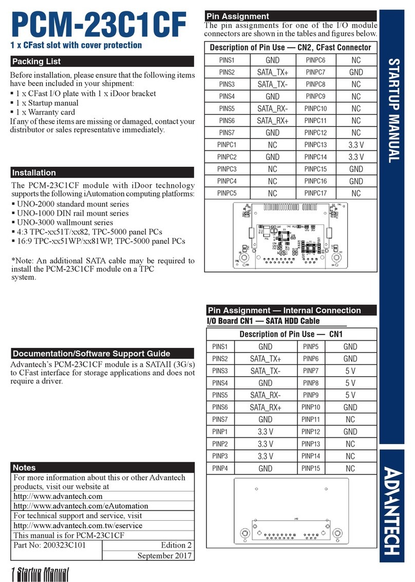
1 Startup Manual
STARTUP MANUAL
PCM-3810I
PCI-104 12-bit Multifunction Module
Before installation, please make sure that you have:
• PCM-3810I Module
• Driver CD
• Startup Manual
If anything is missing or damaged, contact your
distributor or sales representative immediately.
For more detailed information on this product,
please refer to the PCM-3810I User Manual on the
CD-ROM (PDF format).
Documents\Hardware Manuals\PCM\PCM-3810I
FCC Class A
This equipment has been tested and found to comply with
the limits for a Class A digital device, pursuant to part 15 of
the FCC Rules. These limits are designed to provide reason-
able protection against harmful interference when the
equipment is operated in a commercial environment. This
equipment generates, uses, and can radiate radio frequency
energy and, if not installed and used in accordance with the
instruction manual, may cause harmful interference to radio
communications. Operation of this equipment in a residen-
tial area is likely to cause interference in which case the
user is required to correct interference at his own expense.
CE
This product has passed the CE test for environmental spec-
ifications when shielded cables are used for external wiring.
We recommend the use of shielded cables. This kind of
cable is available from Advantech. Please contact your local
supplier for ordering information.
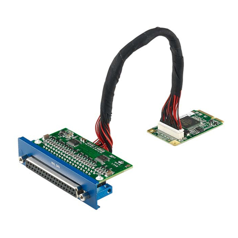
PCM-3810I is a multifunction module for PCI-104 bus.
Their advanced circuit design provides higher quality and
more functions, including 12-bit A/D conversion, D/A con-
version, digital input, digital output, and counter/timer.
Analog Input
Analog Output
Non-Isolated Digital Input/Output
Packing List Specifications
User Manual
Declaration of Conformity
Overview
Notes
For more information on this and other Advantech
products, please visit our websites at:
http://www.advantech.com/eAutomation
For technical support and service:
http://www.advantech.com/support/
This startup manual is for PCM-3810I.
Part No. 2003381010 1st Edition
March 2010
Channels 16 S/E or 8 DIFF or combination
Resolution 12 bits
FIFO Size 4k samples
Max. Sampling Rate 250 kS/s
Input Range and Gain
List
Gain 0.5 1 2
Unipolar - 0~10 0~5
Bipolar ±10 ±5±2.5
Gain 4 8
Unipolar 0~2.5 0~1.25
Bipolar ±1.25 ±0.625
Drift
Gain All Gain
Zero 15 ppm/°C
Span 25 ppm/°C
Input Impedance 300 M / 5pF
Accuracy
INLE: ±1 LSB
DNLE: ±1 LSB
Gain 0.5 1 2
Gain Error
(% FSR)
0.1 0.1 0.2
Gain 4 8
Gain Error
(% FSR)
0.2 0.4
Channels 2
Resolution 12 bits
Output Range
Using Internal
Reference
0~5, 0~10, ±5, ±10 V
Using External
Reference
0~+x V @ +x V
(-10 ≤x ≤10)
-x~+x V @ +x V
(-10 ≤x ≤10)
Accuracy
Relative ±1 LSB
Differential
Non-linearity
±1 LSB (monotonic)
Driving Capability 10 mA
Update Rate Static update
Output Impedance 0.1 ohm max.
Input Channels 16 (shared)
Input Voltage Low 0.8 V max.
High 2.4 V min.
Output Channels 16 (shared)
Output Voltage Low 0.8 V max.
High 2.4 V min.
2 Startup Manual
Counter
General
The PCM-3810I has a built-in DIP switch (SW1),
which is used to define each module’s board ID. When
there are multiple cards on the same chassis, this board
ID setting function is useful for identifying each mod-
ule’s device number through board ID.
* Default setting is 0
Software Installation
Hardware Installation
After the device driver installation is completed, you
can now go on to install the PCM-3810I module on
your computer.
Please follow the steps below to install the module on
your system:
1. Touch the metal part on the surface of your
computer to neutralize the static electricity that
might be in your body.
2. Plug your card into a PCI-104 slot. Use of excessive
force must be avoided; otherwise the card might get
damaged.
Specifications
Channels 3
Resolution 24 bits
Input Frequency 10 MHz max.
Input Voltage Low 0.8 V max.
High 2.0 V min.
I/O Connector Type 50-pin and 26-pin box header
Dimensions 96 x 90 mm (3.8" x 3.5")
Power Consumption 4.2 W typical; 5 W max.
Temperature
Operating 0 ~ 60°C (32 ~ 158°F)
Storage -20 ~ 70° C (-4 ~ 185°
F)
Humidity
Operating 5 ~ 85% RH
non-condensing
Storage 5 ~ 95% RH
non-condensing
Certifications CE certified
Board ID Switch
SW1 Position1 Position2 Position3 Position4
Board ID ID3 ID2 ID1 ID0
15 OFF OFF OFF OFF
14 OFF OFF OFF ON
13 OFF OFF ON OFF
:::::
1 ONONONOFF
0* ON ON ON ON
Installation
Startup Manual 3
Figure 1: 50-pin I/O Connector Pin Assignments
Figure 2: 26-pin I/O Connector Pin Assignments
Pin Assignments
Signal Name Reference Direction Description
AI<0…15> AGND Input Analog Input Channels
0 to 15.
AGND - - Analog Ground.
ANA TRIG AGND Input Analog threshold Trig-
ger.
AI DIG TRIG DGND Input Analog Input Digital
Trigger.
AI PAUSE
GATE
DGND Input Analog Input Pause
GATE.
AI SCAN CLK DGND Input Analog Input Scan
Clock.
AI CONV CLK DGND Input Analog Input Conver-
sion Clock.
AO0 REF
AO1_REF
AGND Input Analog Output Channel
0/1 External Refer-
ence.
AO0_OUT
AO1_OUT
AGND Output Analog Output Chan-
nels 0/1.
AO START
TRIG
DGND Input Analog Output Start
Trigger.
AO CONV
CLK
DGND Input Analog Output Con-
vert Clock.
DIO<0..15> DGND Input Digital Input/ Output
Channel 0 to 15.
DGND - - Digital Ground. This pin
supplies the reference
for the digital channels
at the I/O connector as
well as the +5 V and
+12 V DC supply.
CNT0 CLK
CNT1 CLK
CNT2 CLK
DGND Input Counter 0/1/2 External
Clock Input.
CNT0 OUT
CNT1 OUT
CNT2 OUT
DGND Output Counter 0/1/2 Output.
CNT0 GATE
CNT1 GATE
CNT2 GATE
DGND Input Counter 0/1/2 Gate
Control.
+12V DGND Output +12 VDC Source.
+5V DGND Output +5 VDC Source.
NC - - Not Connected.
4 Startup Manual
Analog Input -
Single-ended Channel Connections
The single-ended input configuration has only one sig-
nal wire for each channel, and the measured voltage
(Vm) is the voltage referring to the common ground.
Analog Input -
Differential Channel Connections
The differential input channels operate with two signal
wires for each channel, and the voltage difference
between both signal wires is measured. On PCM-3810I,
when all channels are configured to differential input,
up to 8 analog channels are available.
Analog Output Connections
PCM-3810I provides two analog output channels, AO0
and AO1. The figure below shows how to make analog
output connections on PCM-3810I.
External Trigger Source Connection
In addition to pacer triggering, PCM-3810I also allows
external triggering for A/D conversions. A low-to-high
edge coming from TRIG will trigger an A/D conversion
on the PCM-3810I board.
Note!: Don't connect any signal to the TRIG pin when
the external trigger function is not being used.
Note!: If you use external triggering for A/D conver-
sions, we recommend you choose differential mode for
all analog input signals, so as to reduce the cross-talk
noise caused by the external trigger source.
Input Connections

Other Advantech Control Unit manuals

Advantech WISE-4610 Series Installation and operation manual

Advantech

Advantech WISE-4610 Series Installation and operation manual

Advantech PCM-3117 Installation and operation manual

Advantech

Advantech PCM-3117 Installation and operation manual

Advantech B+B SmartWorx 232PTC9 User manual

Advantech

Advantech B+B SmartWorx 232PTC9 User manual

Advantech Network Device USB-4761 Installation and operation manual

Advantech

Advantech Network Device USB-4761 Installation and operation manual

Advantech PCM-3612I Installation and operation manual

Advantech

Advantech PCM-3612I Installation and operation manual

Advantech MIC-75G20-10B1 Installation and operation manual

Advantech

Advantech MIC-75G20-10B1 Installation and operation manual

Advantech Adam 4000 Series User manual

Advantech

Advantech Adam 4000 Series User manual

Advantech MIC-3376 User manual

Advantech

Advantech MIC-3376 User manual

Advantech ADAM-3656 Installation and operation manual

Advantech

Advantech ADAM-3656 Installation and operation manual

Advantech SOM-6898 User manual

Advantech

Advantech SOM-6898 User manual

Advantech USB-4750 User manual

Advantech

Advantech USB-4750 User manual

Advantech SOM-7569 User manual

Advantech

Advantech SOM-7569 User manual

Advantech ADAM-6217 User manual

Advantech

Advantech ADAM-6217 User manual

Advantech PCM-233A Installation and operation manual

Advantech

Advantech PCM-233A Installation and operation manual

Advantech PCM-261 Installation and operation manual

Advantech

Advantech PCM-261 Installation and operation manual

Advantech PCM-3614I Installation and operation manual

Advantech

Advantech PCM-3614I Installation and operation manual

Advantech SOM-5893 User manual

Advantech

Advantech SOM-5893 User manual

Advantech IPMI-1000 Installation and operation manual

Advantech

Advantech IPMI-1000 Installation and operation manual

Advantech B+B SmartWorx iMcV-Giga-MediaLinX TX/SFP User manual

Advantech

Advantech B+B SmartWorx iMcV-Giga-MediaLinX TX/SFP User manual

Advantech MOS-1130Y-0201E User manual

Advantech

Advantech MOS-1130Y-0201E User manual

Advantech PCL-832 User manual

Advantech

Advantech PCL-832 User manual

Advantech MIO-6254 Installation and operation manual

Advantech

Advantech MIO-6254 Installation and operation manual

Advantech MIC-75M40 Installation and operation manual

Advantech

Advantech MIC-75M40 Installation and operation manual

Advantech VEGA-330 Installation and operation manual

Advantech

Advantech VEGA-330 Installation and operation manual

Popular Control Unit manuals by other brands

Waveshare RS485 TO ETH user manual

Waveshare

Waveshare RS485 TO ETH user manual

SVF FB9 Installation operation & maintenance

SVF

SVF FB9 Installation operation & maintenance

Panasonic FZ-VCN55 Series operating instructions

Panasonic

Panasonic FZ-VCN55 Series operating instructions

Bailey Infi 90 IMLMM02 Instruction

Bailey

Bailey Infi 90 IMLMM02 Instruction

Baker Hughes Masoneilan MiniTork II 37002 Series instruction manual

Baker Hughes

Baker Hughes Masoneilan MiniTork II 37002 Series instruction manual

Roger H70/200AC Instruction and warnings for the installer

Roger

Roger H70/200AC Instruction and warnings for the installer

Texas Instruments bq24165 user guide

Texas Instruments

Texas Instruments bq24165 user guide

Moog D633 series Mounting and Installation Notes

Moog

Moog D633 series Mounting and Installation Notes

HBM AD105D operating manual

HBM

HBM AD105D operating manual

Vector TLC3-FCR-2T-U Engineering manual

Vector

Vector TLC3-FCR-2T-U Engineering manual

Wistron NeWeb DNUR-SY3 user manual

Wistron NeWeb

Wistron NeWeb DNUR-SY3 user manual

Velleman VSC1 user manual

Velleman

Velleman VSC1 user manual

SMC Networks VM1000 Series Operation manual

SMC Networks

SMC Networks VM1000 Series Operation manual

Carrier 50CJ Installation, operation and maintenance instructions

Carrier

Carrier 50CJ Installation, operation and maintenance instructions

UTC Fire and Security Fenwal 35-63J Series installation instructions

UTC Fire and Security

UTC Fire and Security Fenwal 35-63J Series installation instructions

Crestron CP3 Operation guide

Crestron

Crestron CP3 Operation guide

Cisco 3110 Message guide

Cisco

Cisco 3110 Message guide

Huawei ME909u-523 Acceptance Inspection Guide

Huawei

Huawei ME909u-523 Acceptance Inspection Guide

manuals.online logo
manuals.online logoBrands
  • About & Mission
  • Contact us
  • Privacy Policy
  • Terms and Conditions

Copyright 2025 Manuals.Online. All Rights Reserved.