manuals.online logo
Brands
  1. Home
  2. •
  3. Brands
  4. •
  5. Gespasa
  6. •
  7. Measuring Instrument
  8. •
  9. Gespasa MG-80 User manual

Gespasa MG-80 User manual

MG-80 CODE 32000
VOLUMETRIC MECHANICAL METER
MG-80V CODE 32070
VOLUMETRIC MECHANICAL METER with VITON JOINTS
MGI-80 CODE 32050
VOLUMETRIC MECHANICAL METER WITH PULSER
MGI-80V CODE 32230
VOLUMETRIC MECHANICAL METER WITH PULSER and VITON JOINTS
INSTRUCTION MANUAL
WARRANTY AND CONFORMITY DECLARATION
MG-80
2
1
27
26
25
24
34
23
17
22
21
20
12
19
18
17
16
15
14
13
10 9
8
7
6
5
4
11
31
25
33
35
32
25
31
30
29
28
37 38
39
40
41
MGI-80
PULSER
EMISOR DE IMPULSOS
No. DESCRIPTION CODE
1 1" INLET/OUTLET PLUG 320004001
2 24x3.5 mm JOINT 803100022
2 D.24x3.5 mm VITON JOINT 803101022
3 5.28x1.78 mm CALIBRATION JOINT 803100024
3 D.5.28x1.78 mm VITON CALIBRATION JOINT 803101024
4 PLUG WITH PROTECTION REGULATION 320004004
5 D.9.5x1.5 mm JOINT 803100045
5 D.9.5x1.5 mm VITON JOINT 803101031
6 10x47 mm FLOW SCREW 320004006
7 HOUSING FIXATION SUPPORT 320004007
8 METER HOUSING 320004008
9 80x3 mm VITON JOINT 803101025
10 MEASURING CHAMBER 320002000
11 D.2x16 mm DIN.6325 PIN 804000001
12 BLACK RUBBER NUT CAP 320004010
13 SPECIAL SQUARE VITON JOINT 320704011
14 CENTRAL COVER 320004012
15 M-5x22 mm DIN.912 SCREW 805400008
16 RESET DRIVE 320005001
17 D.4.2x9.5 mm DIN.7981 ZINC-PLATED SCREW 805404003
18 3-DIGIT PLATE 320004113
19 NUMERATION SET COVER 320004014
No. DESCRIPTION CODE
20 M-4 WASHER 800300001
21 D.3.5x9.5 mm DIN.7981 ZINC-PLATED SCREW 805404002
22 NUMERATION 320005002
23 CONICAL GEAR 320001002
24 D.3.69x1.78 mm JOINT 803100023
24 D.3.69x1.78 mm VITON JOINT 803101023
25 GEAR WHEEL RING 320001005
26 GEAR WHEEL 320001003
27 DOUBLE PINION 320001004
28 MEASURING BOX 320002001
29 NUTATING DISC 320002002
30 TOP COVER 320002003
31 COVER LEVER 320002004
32 MEASURING BOX SUPPORT 320002006
33 CM GEAR MEASURING UNIT PINION 320002005
34 D.7 x D.4x6 mm SLEEVE 320004016
35 4x15 mm LEVER SHAFT 320002007
37 PULSER 805800002
38 TRANSMISSION GEAR 805890003
39 3x6 mm ALLEN STUD 805701001
40 M-3x5 mm DIN.7985 SCREW 805406003
41 3-DIGIT ENCODER SUPPORT 321105009
M-1
Partida Horta d’Amunt s/n · Apdo. de Correos nº 149
25600 BALAGUER (Lleida) · SPAIN
++34 (9)73 451 072
++34 (9)73 448 400
[email protected] · http://www.gespasa.es
1. TECHNICAL FEATURES
MG-80 · MGI-80 (MG-80V · MGI-80V)
Flow: From 10 to 90 l/min
Accuracy: ±1 %
Connections: Inlet 1" GAS (BSP), with three optional positions.
Outlet 1" GAS (BSP), with two optional positions.
Counter: Mechanical · 3 digits (999 litres) Partial Indicator
· 6 digits (999,999 litres) Totalizator
Resistance Pressure: 13 bar
Test Pressure: 6 bar
Max. Operating Pressure: 3.5 bar
Measuring Chamber: Disc Fireproof
Construction: Made in non-toxic recyclable plastic with Viton-nitrilic joints and fire-
proof chamber
Maximum Ambient Temperature: 60 ºC
Additional Adaptors: It can be supplied with special Male/Female Adaptors, in NPT, BSW, BSF, BRIGGS thread sizes.
Size: 150x150x170 mm
Total Weight: 1.6 kg
MG-80 · MG-80V DESIGN FACTORS
The MG-80 meter is for private use.
The 1" GAS (BSP) Female Inlet and Outlet Threads take part of the housing. It has 3 inlets. They can be seen from the back: frontal, left lateral
and bottom. It also has 2 outlets. They can be seen from the back: right side and top.
The meter is delivered with horizontal inlet and outlet. Nevertheless, the user can change their position in a short time; the plugs of the desired
direction must be taken out and put them on the non-desired direction. The inner threads have joints which guarantee the sealing; you must only
tighten until its locking, giving up pastes, liquids and sealing products.
The MG-80 volumetric mechanical meters have two numerations (registers):
- The partial with three big numbers where it is possible to read up to 999 litres. It can be reset through a lateral wheel after each supply.
- The 6-digit totalizer with capacity up to 999,999 litres; after that and with its operation, it is automatically reset, starting the cycle again.
MGI-80 · MGI-80V FEATURES
The MGI-80 · MGI-80V pulsers are different from the MG-80 meter. They have a pulser in its inner of 2 communication channels where the con-
nection to a consumption controller is allowed. It also has a lateral packing gland and 90 cm of connection cable.
There is a cable of five little wires from the encoder:
Brown colour with 6-24 V feeding, white 0 V, A (or 1) green channel, B (or 2) yellow channel, and Z (or 3) grey channel.
The encoder generates 10 pulses per channel and supplied litre.
Please read all the instructions carefully before using the product. The people who do not know the instructions must not use it.
This manual describes how to use the mechanical meter according to the project hypothesis, the technical features, the types of installation, the
use, the maintenance and the training regarding to possible dangers.
The operation manual must be considered as a part of the mechanical meter and keep it for future inquiries during all its working life.
We suggest keeping it in a dry and protected place.
The manual reflects the technical situation in the meter sale and cannot be considered inadequate for the reason of being updated according to
the new experiences. The manufacturer reserves the right to update the production and the manuals without being forced to update the production
and previous manuals.
The meter security, regarding to the equipment quality and reliability, is determined by the EC Directive Regulations and endorsed by the quality
controls of the enterprise leaders in the sector. It also guarantees the toxicity absence and the negative ecological effects. To avoid the possible
accidents, it is advisable to read the following warnings and cautions carefully:
3.1. A wrong meter installation or use can cause serious effects, both physical and material.
In
Entrada
In
Entrada
In
Entrada
Out
Salida
Out
Salida
Brown
Green
Yellow
Grey
White
MGI-80
Pulser
V + 6 to 24 V
Channel A
Channel B
Channel Z
0
2. WARNINGS
3. SECURITY INSTRUCTIONS
3.2. Do not smoke when the flammable fluids, hydrocarbons, are transferred. A FIRE CAN BE CAUSED.
3.3. This meter has been designed for the hydrocarbon measurement, but with some restrictions regarding to its use with
certain liquids.
The compatibility list is the following one:
• MG-80 is suitable for diesel.
• MG-80V is suitable for diesel, petrol and aviation fuels.
• MGI-80 and MGI-80V are suitable for diesel.
The meters are precalibrated in the factory. IT IS ADVISABLE TO CALIBRATE THEM ONCE THEY HAVE BEEN INSTALLED.
Each liquid type has its own density and viscosity. In order to get a reliable measurement, it is advisable to make this calibration with an approved
test tube or decalitre. It can be used a container, whose capacity you should know previously.
Calibration procedure
6.1. For an exact calibration, the meter, the hose, the nozzle and the pump must be full of liquid, but free of air. This is achieved emptying from 10
to 20 litres of liquid and closing the nozzle, without stopping the pump until the operation is finished.
6.2. Fill the approved decalitre until the exact measurement (10 or 20 litres). The bigger the recipient is, the better accuracy you will have.
6.3. If the quantity does not correspond to the emptied liquid in the recipient, it needs to be calibrated.
The meters are very easy to install. Then it is specified the appropriate process to make the installation more comfortable, using the six possible
combinations to the pipe and hose assembly.
4.1. Check the most right fluid direction. It is not necessary to disassemble the meter to change the liquid direction.
4.2. Take out the chosen inlet and outlet hole plugs, as well as their joints.
4.3. Put these joints and plugs in the holes that are not going to be used. It is not necessary to put other joints in the threads. Everything is foreseen
to get a total sealing. The thread end has a nitrilic joint (or Viton joint according to the model) which guarantees the total sealing with a minimum
pressure.
4.4. It is necessary to use sealing components on the installation pipes and threads, which are resistant to the products to transfer.
3.4. Make sure of the correct installation of the decanting circuit, checking the leak absence.
3.5. It is advisable the assembly of a check valve in the meter outlet. So, it is avoided some problems on the pumping and measuring equipment,
for instance because of an accidental tread on the delivery hose.
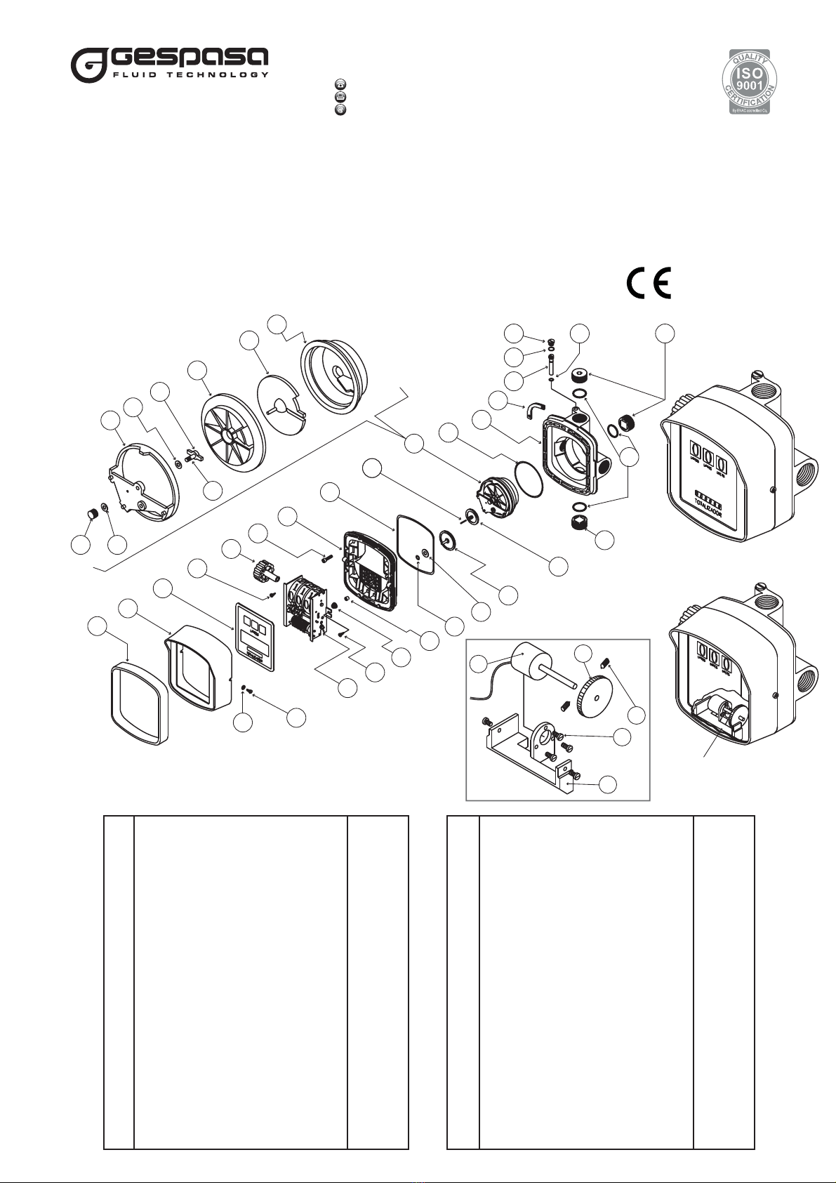
It is not advisable to disassemble the meter, but if you are going to do this, take into account the meter has a measuring chamber with liquid
distributor holes, a partial and a total numeration register. Please see the explosion view section. The meter is divided into parts so that it is easier
to identify each part. Please use the corresponding code number when asking for it, and take into account the meter can be taken into pieces
without disassembling the pipes.
5.1. Take out the lateral reset drive (16).
5.2. Take out the rubber nut cap (12).
5.3. Slacken the two screws (21) and remove the unit numerator cover (19).
5.4. Unscrew the screws (17) that subject the numeration (22) and take it out carefully.
5.5. Unscrew the 8 screws (15) of the central cover (14) from the housing fixation supports (7). When the central meter cover (14) is opened, be
careful because there are the measuring chamber mechanism gears in its inner.
5.6. For its assembly, follow the above described steps in the reverse order, taking into account the correct installation of the housing fixation
supports (7), Viton joint (9) and the special square Viton joint (13).
6.4. First, take out the plug (4) and turn the screw (6) clockwise. Then, the flow percentage decreases. Turning it anticlockwise, it increases. A
complete turn varies the measurement, more or less in 0.4 litres each 10 litres.
6.5. If you want to guarantee a correct calibration, you have to repeat the above step three or four times. If the result is correct, a good adjustment
will be achieved , and the meter will be ready to be used. Do not exceed the pressure of 3.5 bar, and do not work less than 1 bar.
6.6. The MG-80 meter can work by gravity or with a pump. Remember the suitable minimum pressure is 1 bar with a minimum flow of 15 l/min,
and an accuracy of ±1%. If you use it by gravity, it is possible there is some mistake in the measurement due to the different liquid height that the
tank may have. It is always advisable to install a pump.
3.6. IMPORTANT
The meter has a high accuracy because of the minimum tolerances there are in its measuring chamber. It is one of the most
exact meters in the market.
IT IS OBLIGATORY TO INSTALL THE RED ADAPTER WITH FILTER of 350 µm (micron) or the PLASTIC FLANGE KIT WITH FILTER of
350 µm (micron) in the inlet used by the meter in order to avoid the measuring chamber is blocked because of the solid impurities.
IT IS ALSO ADVISABLE to INSTALL the FG-100 MICROFILTER in the pump suction if you want to get a better microfiltration.
4. INSTALLATION
5. DISASSEMBLE-ASSEMBLE
6. CALIBRATION
The calibration process must be done with the nozzle totally open. Never calibrate it with the nozzle mid-opened.
7. MAINTENANCE
The MG-80 meters do not need maintenance. It is possible that some liquids are dried up on the measuring chamber inner, causing an obstruction.
If this happens, they must be cleaned with a lot of care, and when they are going to be mounted, ensure it is correctly done.
If hydrocarbons are used, they can be cleaned with cleaning liquids or oil. Follow the instructions from section 5. Disassemble-Assemble. When
the MG-80 meter is stored for a long time, clean it conscientiously. It will remain protected and ready for a new starting.
WHEN USING THE METER FOR THE ADBLUE/DEF TRANSFER
Due to its chemical composition, the AdBlue/DEF is easily solidified making crystals when it is in touch with the air. These crystals may block the
different mobile parts of the meter. To avoid this characteristic affects to the kit operation, please take into account the following:
If the meter is stopped some days without working, flow demineralized water (preferentially in hot) many times so that the AdBlue/DEF rests are
eliminated and avoid these crystallize in its inner.
8. REPAIR
The authorized repair workshops are the only ones which can repair the motor in bad state. The meters must be cleaned and dried up before its
delivery to be repaired.
When ordering spare parts, make sure it is given the correct code of the spare part, the manufacturing date and the pump serial number. This will
guarantee the correct supply of the requested spare part.
1. All the products manufactured by TOT COMERCIAL SA have a WARRANTY of 12 (twelve) months from their purchase, against any manufacturing
defect.
2. TOT COMERCIAL SA guarantees, in the warranty period, the change/the devolution of the defective part or product. This material must be sent
with prepaid freight to our factory or any appointed technical service.After our technical inspection, it will be determined whether the responsibility
is from the manufacturer, the user, the installer or the delivery transport.
3. The warranty does not cover: the inadequate use, the negligence, the corrosion, the abuse, the manipulation or the wrong installation of the
products, the use of non-original spare parts or not concerning to the specific model. All the manufactured and/or commercialized equipment
must be installed according to the manufacturer’s instructions.
4. The accessories and the products not manufactured by TOT COMERCIAL SA are liable for their original manufacturer’s warranty.
5. Because of the constant innovations and development, TOT COMERCIAL SA reserves the right to modify the specifications of its products and
publicity, without prior notification.
9. PROBLEM GUIDE
BREAKDOWN POSSIBLE CAUSE SOLUTION
The litres are passing, but the
numeration does not count. - there are impurities on the measuring
chamber. - clean the measuring chamber (10). If it is used to transfer AdBlue/DEF,
please clean with demineralized water (preferentially in hot).
Loss of liquid - Allen screws loose
- because of the overpressure the joint has
been moved.
- joint breaking
- tighten up the Allen screws (15).
- replace the joint (9 or 13).
The total or partial numeration
does not point correctly. - numeration breaking - replace the numeration (22).
You read more or less litres than
those supplied. - calibration failure
- the minimum flow is not respected. - calibrate the meter according to the section 6.
- the minimum supply flow must be 15 l/min to assure a trustworthy measurement.
Low flow rate - impurities on the measuring chamber
- dirtiness on the red adaptor - clean the measuring chamber (10).
- clean the inner sieve.
It counts too quick or too slow. - bad calibration
- air inlet
- blocked gears
- the minimum flow is not respected.
- calibrate the meter according to the section 6.
- look for and repair the possible losses or air inlets on the system.
- clean and replace the gears (23, 26, 27 or 33).
- the minimum supply flow must be 15 l/min to assure a trustworthy measurement.
10. WARRANTY
11. EU CONFORMITY DECLARATION
Manufacturer: TOT COMERCIAL SA - Partida Horta d'Amunt s/n - Apartado Correos nº 149 - 25600 BALAGUER (Lleida) SPAIN
STATES under its own responsibility the supplied product: VOLUMETRIC MECHANICAL METER· Make: GESPASA
Model: MG-80 · MGI-80 · MG-80V · MGI-80V
is in accordance with the following legislative and/or normative documents
DIRECTIVES Nr. and issued rules date
2006/42/UE: Safety of machinery EN-ISO 12100:2012
- This Declaration will lose its validity in case that any modification is made without the explicit manufacturer's consent.
Balaguer, November 2017
Andreu Pané

This manual suits for next models

7

Other Gespasa Measuring Instrument manuals

Gespasa MGI-110 User manual

Gespasa

Gespasa MGI-110 User manual

Gespasa MGE-110 User manual

Gespasa

Gespasa MGE-110 User manual

Gespasa MG-80 User manual

Gespasa

Gespasa MG-80 User manual

Gespasa MGE-110 User manual

Gespasa

Gespasa MGE-110 User manual

Gespasa BGE-110HI User manual

Gespasa

Gespasa BGE-110HI User manual

Gespasa MGE-250 1 User manual

Gespasa

Gespasa MGE-250 1 User manual

Popular Measuring Instrument manuals by other brands

Extech Instruments MO290 user guide

Extech Instruments

Extech Instruments MO290 user guide

Marconi Instruments TF 2005R instruction manual

Marconi Instruments

Marconi Instruments TF 2005R instruction manual

Eurotron MicroCal T100+ instruction manual

Eurotron

Eurotron MicroCal T100+ instruction manual

Hanna Instruments HI 2214 instruction manual

Hanna Instruments

Hanna Instruments HI 2214 instruction manual

PKP DG03 instruction manual

PKP

PKP DG03 instruction manual

RMG TRZ 04 operating instructions

RMG

RMG TRZ 04 operating instructions

ProsKit NT-6540 user manual

ProsKit

ProsKit NT-6540 user manual

HP 1660 Series Service guide

HP

HP 1660 Series Service guide

Larsen & Brusgaard PROTRACK II manual

Larsen & Brusgaard

Larsen & Brusgaard PROTRACK II manual

Reflex Fillguard Plus Instructions for use

Reflex

Reflex Fillguard Plus Instructions for use

RigExpert AA-2000 ZOOM user manual

RigExpert

RigExpert AA-2000 ZOOM user manual

ADInstruments pH Amp owner's guide

ADInstruments

ADInstruments pH Amp owner's guide

PCB Piezotronics IMI SENSORS HT624B01 Installation and operating manual

PCB Piezotronics

PCB Piezotronics IMI SENSORS HT624B01 Installation and operating manual

Aquametro Oil & Marine CONTOIL VZD2 Mounting and operating instructions

Aquametro Oil & Marine

Aquametro Oil & Marine CONTOIL VZD2 Mounting and operating instructions

LB Altimeters ARES II manual

LB Altimeters

LB Altimeters ARES II manual

Landis & Gyr Cashpower Gemini PLC user guide

Landis & Gyr

Landis & Gyr Cashpower Gemini PLC user guide

VWR MCT 100 instruction manual

VWR

VWR MCT 100 instruction manual

Chauvin Arnoux C.A 10141 user manual

Chauvin Arnoux

Chauvin Arnoux C.A 10141 user manual

manuals.online logo
manuals.online logoBrands
  • About & Mission
  • Contact us
  • Privacy Policy
  • Terms and Conditions

Copyright 2025 Manuals.Online. All Rights Reserved.