Gespasa BGE-110HI User manual

MGE-110HI CODE 32601
ELECTRONIC GEAR METER WITH PRESET AND AUTOMATIC STOP
MEDIDOR DE ENGRANAJES ELECTRÓNICO CON PRESELECCIÓN Y PARO AUTOMÁTICO
INSTRUCTION MANUAL
WARRANTY AND CONFORMITY DECLARATION
MANUAL DE INSTRUCCIONES
GARANTÍA Y DECLARACIÓN DE CONFORMIDAD
M-206
*The inlet is through the connection which has the joint.
La entrada es por la conexión que tiene la junta tórica.
Nº DESCRIPTION CODE
DESCRIPCIÓN CÓDIGO
1 M-4x70 mm DIN. 912 ZINC COATED SCREW 805400041
Tornillo M4x70 mm DIN. 912 zincado
2 MGE-110HI FACE PLATE 326004009
Carátula MGE-110HI
3 MGE-110 PP PLASTIC COVER 326001003
Tapa MGE-110 plástico PP
4 111.4x34.9x2 mm TRANSPARENT METHACRYLATE 803802013
Metacrilato transparente 111,4x34,9x2 mm
5 MGE-110 HI ELECTRONIC BOARD + 230 V POWER BOARD 326004001
Placa electrónica MGE-110HI + placa potencia 230 V
6 D. 3.5x9.5 mm DIN. 7981 SHEET SCREW 326004002
Tornillo D. 3,5x9,5 mm DIN. 7981 chapa
7 PG-11 PACKING GLAND NUT 806402001
Tuerca prensaestopas PG-11
8 PG-11 PACKING GLAND 806400001
Prensaestopas PG-11
9 MGE-110 HI ELECTRONIC SEPARATOR SHEET 326001004
Chapa separador electrónica MGE-110 HI
10 M-3.5x9.5 mm DIN. 7981 ZINC COATED SCREW 805404002
Tornillo M-3,5x9,5 mm DIN. 7981 zincado
11 180º HALL EFFECT BOARD 326004012
Placa efecto HALL 90º
12 180º REED PLATE 326004011
Placa REEDS 90º
13 iButton READER 251208009
Lector iButton
14 D. 38x2.5 mm NBR JOINT 803100056
Tórica D. 38x2,5 mm NBR
15 MGE-110 ALUMINIUM BODY 326001000
Cuerpo medidor MGE-110 aluminio
16 D. 6x10 mm GEAR MAGNET 322001008
Imán engranaje D. 6x10 mm
17 GEAR 326002000
Engranaje medidor MGE-110
18 D. 8x45 mm STAINLESS GEAR SHAFT 326001002
Eje INOX. engranaje D. 8x45 mm
19 DIN. 6325 D. 3x16 mm PIN 804000021
Pasador DIN. 6325 D. 3x16 mm
20 D. 74x2 mm NBR JOINT 803100076
Torica D. 74x2 mm NBR
21 ALUMINIUM METER COVER 326001001
Tapa medidor MGE-110 aluminio
22 M-5x16 mm DIN.912 ZINC COATED SCREW 805400044
Tornillo M5x16 mm DIN.912 zincado

MGE-110HI INSTRUCTION MANUAL
Manual de instrucciones
2
1. TECHNICAL SPECIFICATIONS 1. CARACTERÍSTICAS TÉCNICAS
The meter has an aluminium measuring chamber and 2-high accuracy oval
gears. It is suitable for the transfer of mineral oil, diesel, heating oil, motor
oil up to SAE-140 (please ask for other liquids). It is inserted into the fuel
and oil distribution line and its operation is private. The calibration
parameters and the totalizer litres are saved in a PERMANENT memory.
El medidor posee una cámara de medición de aluminio y 2 engranajes
ovalados de gran precisión. Está concebido para el transvase de aceite
mineral, diésel, petróleo para calefacción, aceite para motores hasta SAE-
140 (consultar otros líquidos). Se intercala en la línea de distribución de
carburantes y aceites y su uso es privado. Los parámetros de calibración y
totalizador de litros están almacenados en memoria NO VOLÁTIL.
This also has built in a keypad and LCD-Display to make easier its
visualization. Dispone además un teclado y un gran Display-LCD para obtener así una
visualización fácil y sencilla.
The MGE-110HI meter is composed of two pulse emitters (REED type)
which are welded to an electronic plate fixed directly to the meter and two
magnets fixed to one of the gears.
El MGE-110HI está compuesto por dos emisores de impulsos tipo REED
que están soldados en una placa electrónica fijada directamente encima del
medidor y dos imanes fijados en uno de los engranajes.
Because of the two magnets one of the gears has, the MGE-110HI meter
emits 4 pulses per each round to the electronics. Debido a los dos imanes que contiene uno de los dos engranajes, el
medidor MGE-110HI emite 4 impulsos por cada vuelta a la electrónica.
MGE-110HI
Flow Caudal 5-110 l/min
Channels Canales 2
Phase-out channel Desfase canales 90º
Pulses per channel Pulsos por canal 41 pulses x litre and channel
pulsos x litro y canal
Max. pressure loss Pérdida presión máxima 0.3 bar (diesel)
Max. pressure Presión máxima 55 bar
Temperature Temperatura -10 / +50 ºC
Max. humidity Humedad máxima 95 H.R.
Viscosity Viscosidad 2-2000 cSt
Accuracy Precisión ±0.5 %
Noise Ruido LEQ
A
< 70dBA
Repetitivity Repetitividad 0.2 %
Inlet-outlet connections Conexiones entrada-salida 1" BSP Flange / Brida
Dimensions Dimensiones 126 x 127 x 150 mm
Weight Peso 1.5 kg
2. WARNINGS 2. ADVERTENCIAS
Please, read all the instructions carefully before using the product.
The people who do not know these instructions must not use it. Leer con cuidado todas las instrucciones antes de utilizar el producto.
Las personas que no conozcan las instrucciones para el uso no deben
utilizarlo.
This manual describes how to use the meter according to the project
hypothesis, the technical features, the types of installation, the use, the
maintenance and the training regarding to possible dangers.
El presente manual describe el modo de utilizar el medidor según las
hipótesis del proyecto, las características técnicas, los tipos de instalación,
el uso, el mantenimiento y la formación relativa a los posibles riesgos.
The operation manual must be considered as a part of the electronic
meter and keep it for future inquiries during all its working life. We
suggest keeping it in a dry and protected place.
El manual de instrucciones debe considerarse como una parte del
medidor y conservarse para futuras consultas durante toda la vida útil
de la misma. Se aconseja conservarlo en lugar seco y protegido.
The manual reflects the technical situation at the moment of the meter sale
and cannot be consider inadequate for the reason of being updated
afterwards according to the new experiences. The manufacturer reserves
the right to update the production and the manuals without being forced to
update the production and previous manuals.
El manual refleja la situación técnica en el momento de la venta del
medidor y no puede considerarse inadecuado por el hecho de ser
posteriormente actualizado según las nuevas experiencias. El fabricante se
reserva el derecho de actualizar la producción y los manuales sin estar
obligado a poner al día la producción y los manuales anteriores.
ATTENTION:
The water and humidity contact can damage the
electronics. This meter is not water resistant. It must be
installed indoors or in protected sites against the
inclemency of the weather.
ATENCIÓN:
El contacto con el agua y la humedad puede dañar la
electrónica. El equipo no es resistente al agua. Instalar en
interiores o en lugares protegidos de las inclemencias
meteorológicas.
3. SECURITY INSTRUCTIONS 3. INSTRUCCIONES DE SEGURIDAD
The meter security with regard to the material quality and reliability is
determined by the EC Directive Regulations and is endorsed by the quality
controls of the enterprise leaders in the sector, and it also guarantees the
toxicity absence and the negative ecological effects. To avoid the possible
accidents, it is advisable to read the following warnings and cautions
carefully:
La seguridad de los medidores, en cuanto a calidad y fiabilidad de los
materiales, viene determinada por las reglamentaciones de la Directiva de
la CE y avalada por los controles de calidad de las empresas líderes en el
sector, garantizando además la ausencia de toxicidad y efectos ecológicos
negativos. Para evitar posibles accidentes, recomendamos leer
detenidamente los siguientes avisos y precauciones:
3.1. ATTENTION:
A wrong meter installation or use can cause serious effects
both physical and material.
It is advisable to install a filter in order to avoid the solid
inlet in the measuring chamber.
3.1. ATENCIÓN:
Una mala instalación o uso de este medidor puede causar
graves consecuencias, tanto físicas como materiales o
medioambientales.
Se aconseja la instalación de un filtro para evitar la entrada
de sólidos en la cámara de medición.
3.2. ATTENTION:
When transferring the inflammable fluids, hydrocarbons,
do not smoke in the work environment.
A FIRE CAN BE CAUSED.
3.2. ATENCIÓN:
No fumar en el ambiente de trabajo cuando se utilicen
líquidos inflamables, hidrocarburos.
PUEDE ORIGINARSE UN INCENDIO.

MGE-110HI INSTRUCTION MANUAL
Manual de instrucciones
3
3.3. ATTENTION:
Ensure the correct installation of the decanting circuit,
checking the leak absence.
3.3. ATENCIÓN:
Asegurarse de la correcta instalación del circuito
hidráulico, comprobando la ausencia de fugas.
4. INSTALLATION 4. INSTALACIÓN
4.1. Connect the inlet liquid tube at the meter side where there is the slot to
put the joint. The meter measures in only one direction (inlet -> outlet). 4.1. Conectar el tubo de entrada de líquido en el lado del medidor que
dispone de la ranura para colocar la junta tórica. El medidor mide en una
única dirección (entrada -> salida).
4.2. The meter is assembled in such a way that the digit reading and its
keys are aligned with the tube inlet/outlet holes.
4.2. El medidor se suministra montado de tal forma que la lectura de los
dígitos y las teclas están alineados con los agujeros de entrada/salida de
las tuberías.
When turning 90º the frontal cover in order to make easier its reading and
key handling, unscrew the 4 screws (1) with an Allen screwdriver and put
the cover in the desired position.
Si se desea girar la tapa frontal 90º para facilitar la lectura y la manipulación
de las teclas del medidor, destornillar los 4 tornillos (1) con una llave tipo
Allen y colocar la tapa en la posición deseada.
Before closing the cover, check that the joint is well-positioned and screw
again the screws (1) in its holes. Antes de cerrar, verificar que la junta tórica se encuentra en la posición
correcta y volver a roscar los tornillos (1) en sus orificios correspondientes.
4.3. ATTENTION:
Use sealing elements with a lot of care. Please take care no
remains go into the measuring chamber. This can cause a
meter breakdown.
4.3. ATENCIÓN:
Utilizar elementos sellantes con sumo cuidado. Sobre todo,
que no entren restos en la cámara de medición. Se podría
producir una avería en el medidor.
4.4. It is necessary to use sealing components on the installation pipes and
threads that are resistant to the products to be transferred. 4.4. En las tuberías y roscas de la instalación es necesario utilizar
componentes de estanqueidad que sean resistentes a los productos a
transvasar.
4.5. It is very important the leak absence in the suction and delivery lines as
a little air inlet would affect the kit accuracy. 4.5. Es muy importante la ausencia de fugas en las líneas de aspiración e
impulsión ya que una pequeña entrada de aire afectaría a la precisión del
equipo.
5. KEYS AND ITS FUNCTIONS 5. TECLAS Y FUNCIONES
The meter has 4 keys whose functions are the following ones: El medidor dispone de 4 pulsadores. Sus funciones son las siguientes:
TOTAL - CANCEL: While making a preset,
this can be cancelled. When pressing this
key, all the display segments are switched on.
This means the display is correctly working.
When pressing it during 2 seconds, then the
totalizer is displayed.
TOTAL - CANCEL: Mientras se está haciendo
una preselección, permite cancelarla. Si se
mantiene pulsado, todos los segmentos de la
pantalla se encienden, lo que permite verificar
que la pantalla funciona correctamente. Si se
mantiene pulsado durante 2 seg., muestra el
totalizador del equipo.
RESET – ON/OFF: ON: It allows starting the
service, resetting the partial counter and
switching on the pump.
OFF: It allows ending the service, stopping
the pump, adding the partial counter to the
total one, saving it to the permanent memory.
RESET - ON/OFF: Función ON: permite iniciar el
servicio, pone a cero el contador parcial y
enciende la bomba. Función OFF: permite
finalizar el servicio, para la bomba, suma el
contador parcial al contador total y lo guarda en
la memoria no volátil.
x10: It allows presetting. It increases 10 litres
in each keystroke. x10: Permite realizar la preselección. Incrementa
10 litros en cada pulsación.
x1: It allows presetting. It increases 1 litre in each keystroke. x1: Permite realizar la preselección, incrementa 1 litro en cada pulsación.
The display shows the volume with 2, 1 or no decimal, according to the
shown number. For example, if the number is among 0.00 and 999.99, it
shows two decimals; if it is among 1,000.0 and 9,999.9, it only shows one
decimal; and if it is equal to or higher than 10,000, it does not show any
decimal.
La pantalla nos muestra el volumen con 2, 1 o ningún decimal, en función
del número que se visualice. Por ejemplo, si el número está entre 0,00 y
999,99 se visualizan dos decimales; si está entre 1000,0 y 9999,9 sólo se
mostrará un decimal; y si es igual o superior a 10000 no se mostrará
ningún decimal.

MGE-110HI INSTRUCTION MANUAL
Manual de instrucciones
4
6. CALIBRATION 6. CALIBRACIÓN
ATTENTION: The meters are precalibrated in factory
approximately.
CALIBRATE AGAIN THE METER in the installation.
ATENCIÓN: Los medidores vienen con una precalibración
aproximada en fábrica.
SE DEBE CALIBRAR NUEVAMENTE EL MEDIDOR en la
instalación.
6.1. Press the TOTAL - CANCEL and RESET – ON/OFF keys during 15
seconds to enter the calibration menu. The display will show 'P'. 6.1. Para acceder al menú de calibrado se deben mantener pulsadas las
teclas “TOTAL-CANCEL” y “RESET-ON/OFF” durante 15 seg. y se activará
el menú correspondiente, en la pantalla aparecerá 'P'.
6.2. Through the dispenser device and a calibrated recipient, fill some
amount of liquid so that the display meter does not exceed 99.99; then
press TOTAL-CANCEL to accept. Write down the liquid volume in litres (or
the volume unit you are working with) and decimals with the maximum
resolution it is possible.
6.2. Mediante el dispositivo dispensador y un recipiente calibrado, hay que
llenar una cantidad de líquido de forma que el contador de la pantalla no
supere 99,99; a continuación pulsar “TOTAL-CANCEL” para aceptar.
Anotar el volumen del líquido en litros y decimales (o en la unidad de
volumen que se esté trabajando) con la máxima resolución posible.
6.3. The display shows 'L0.00', blinking the digit at the right , meaning it is
the editable digit. Then press the RESET – ON/OFF key and the digit
increases. In order to validate this digit and go on with the next one, press
the TOTAL - CANCEL key, and it will blink the next digit at the left. Finally,
once the fourth digit is accepted with the TOTAL - CANCEL key, the device
will calculate the calibration factor in accordance with its data: pulse number
and the amount of entered liquid.
6.3. Ahora la pantalla muestra 'L0.00' con el dígito de más hacia la derecha
intermitente que indica que es el dígito que se está editando. Cada vez que
se pulsa “RESET-ON/OFF” el dígito se incrementa. Para validar el dígito y
pasar al siguiente hay que pulsar “TOTAL-CANCEL” y se pondrá
intermitente el siguiente dígito de la izquierda. Después del cuarto dígito, al
aceptarlo con “TOTAL-CANCEL”, el dispositivo calcula el factor de
calibración en función de los datos que tiene: nº de pulsos y cantidad de
líquido introducido.
6.4. In this point the display will show '-----' during some seconds, and then
it will intermittently show the calculated calibration factor, the first 5 decimals
of the factor. If there is any calculation error, the display will show ‘Err C’
and reject this factor.
6.4. En este punto en la pantalla aparecerá '-----' durante unos segundos y
después mostrará intermitentemente el factor de calibración calculado, los
5 primeros decimales del factor. Si ha habido algún error de cálculo,
mostrará en la pantalla ‘Err C’ y desestimará este factor.
6.5. Pressing the TOTAL - CANCEL key, the calibration factor is accepted
and saved in the permanent memory. From now this is the used calibration
factor. Pressing the RESET – ON/OFF key, the calculated factor is rejected.
6.5. Pulsando “TOTAL-CANCEL” se acepta el factor de calibración y se
guarda en la memoria no volátil, utilizando este factor a partir de este
momento. Pulsando “RESET-ON/OFF” se rechaza el factor calculado.
6.6. If a pulse value of 0 is accepted, the device will show ‘Err P’, and if a
litre value of 0.00 is typed, it will show ‘Err L’.
Some pulse/volume combinations can also give a calculation error; the
display will show ‘Err C’.
6.6. Si se intenta aceptar un valor de pulsos 0, el dispositivo mostrará el
error ‘Err P’ y si se intenta entrar un valor de litros 0,00 mostrará ‘Err L’.
Algunas combinaciones de pulsos/volumen también pueden dar error en los
cálculos, visualizando en la pantalla ‘Err C’.
ATTENTION: The calibration process must be made with
the meter at its maximum flow or at the nominal operation
flow of the installation. Otherwise, the calibration will not
be exact.
A
TENCIÓN: El proceso de calibrado debe realizarse con el
medidor al máximo caudal posible o en el caudal nominal
de funcionamiento de la instalación, ya que, de lo
contrario, el calibrado que se realiza no es exacto.
7. USE INSTRUCTIONS 7. INSTRUCCIONES DE USO
7.1. Meter with litre preset 7.1. Medidor con preselección de litros
The meter counts the litres in an automatic way when the fluid goes through
its interior. El medidor contabiliza los litros de forma automática cuando el fluido pasa
por su interior.
The fluid causes the gear movement. These transmit the signal to the
electronic plate which counts the litres, and these are shown in the display.
The meter only counts the litres that pass through the meter in one way.
El fluido provoca el movimiento de los engranajes. Estos transmiten la
señal a la placa electrónica que contabiliza los litros y los muestra en
pantalla. El medidor únicamente contabiliza los litros que pasan por el
medidor en un sentido.

MGE-110HI INSTRUCTION MANUAL
Manual de instrucciones
5
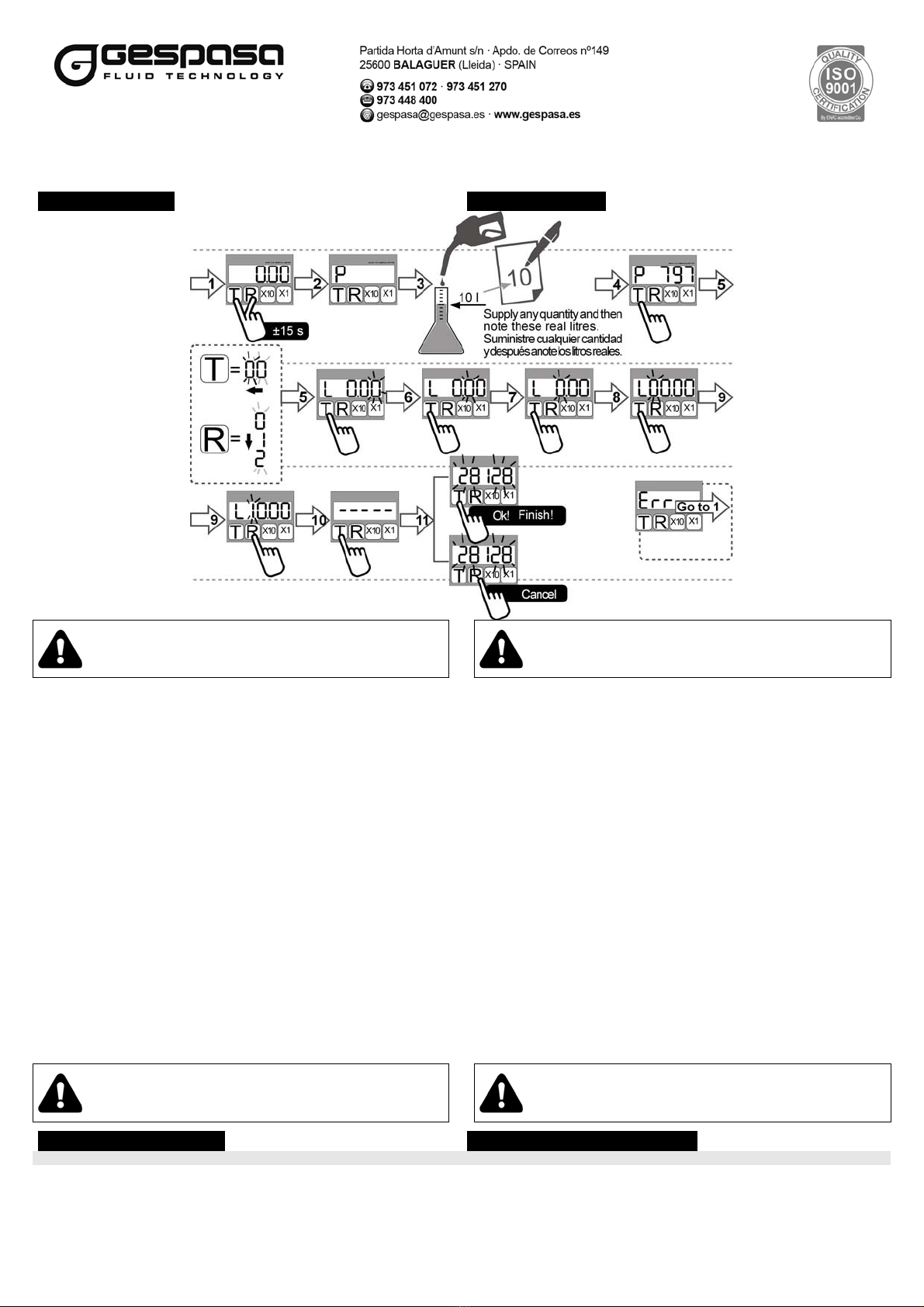
7.1.1. Preset of litres to be supplied 7.1.1.Preselección de litros a suministrar
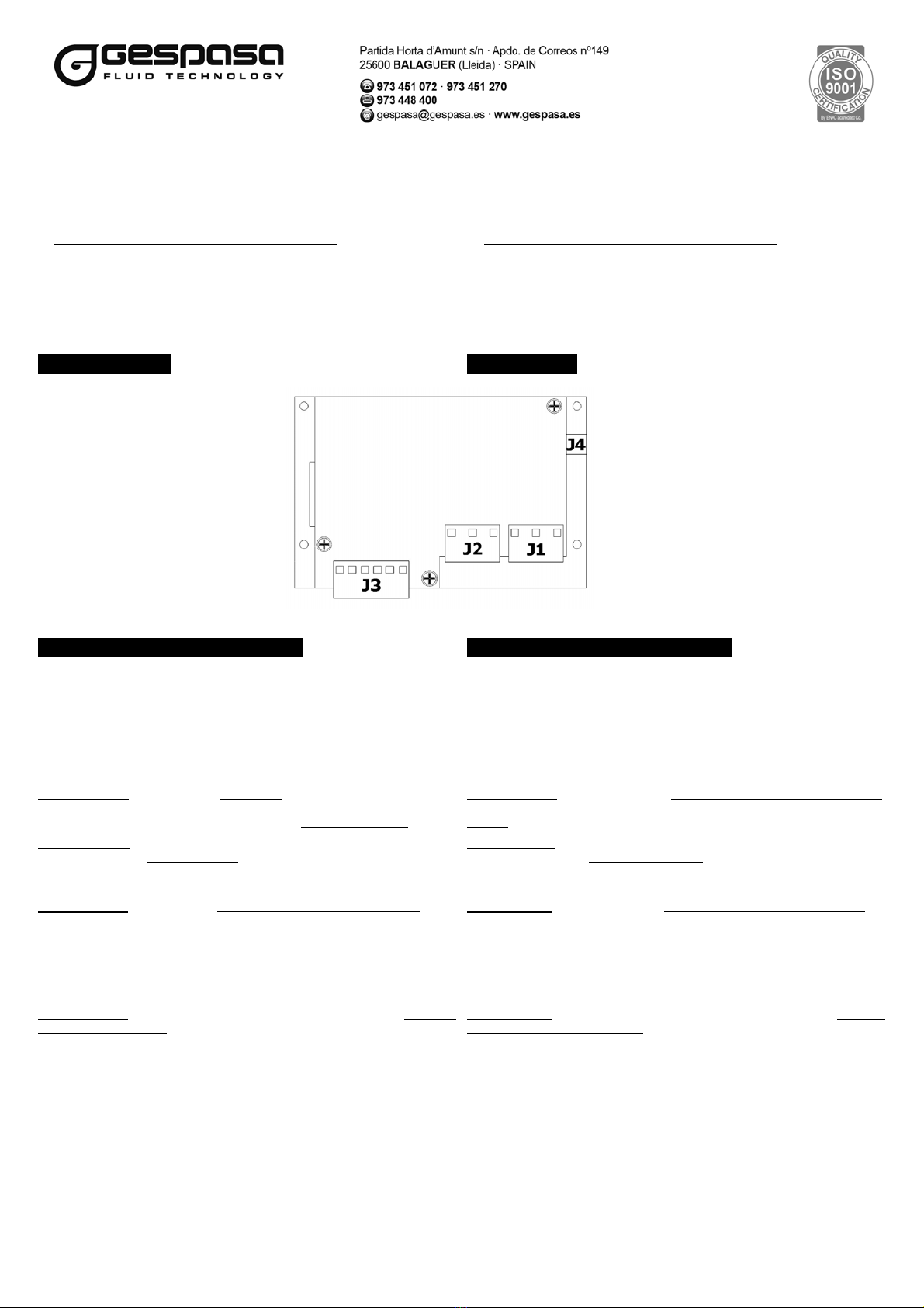
In order to preset the litres, connect previously the motor or solenoid
valve to the J3 connector. (Please see the following section
“Connection”).
Para utilizar el medidor como preseleccionador de litros, hay que
conectar previamente el motor o válvula solenoide al conector J3 (ver
más adelante el apartado "Conexión").
To preset the litres to be supplied, make it before starting the supply
through the keys “x10” and “x1”. Select the amount to supply. To cancel
the typed amount, press “TOTAL-CANCEL” before starting the supply.
If the typed amount is the correct one, start the supply.
Para realizar una preselección de litros a suministrar, ésta debe
realizarse antes de iniciar el suministro. Mediante las teclas “x10” y “x1”
seleccione la cantidad que desee suministrar. Para cancelar la cantidad
introducida pulsar “TOTAL-CANCEL” antes de iniciar el suministro.
Después de introducir la cantidad deseada iniciar el suministro.
When the supplied litres are the same as those preset, the service will
finish, and the pump will be switched off or the solenoid valve will be
activated.
Cuando los litros suministrados sean los mismos que los
preseleccionados, el servicio finalizará y se apagará la bomba o se
accionará la válvula solenoide.
7.2. Use of the meter with identification through iButton keys 7.2. Uso del medidor con identificación mediante llaves iButton
If you have a pack* of 10 or 20 iButton MGE-110HI keys, you can limit the
use of the kit of those users who have an iButton key. *(it is an optional part
· you have to buy it apart from the meter).
Si se dispone de un pack de 10 ó 20 llaves iButton MGE-110HI (se
adquiere por separado al medidor), podrá limitar el uso del equipo a
usuarios que dispongan de una llave iButton dada de alta en el medidor.
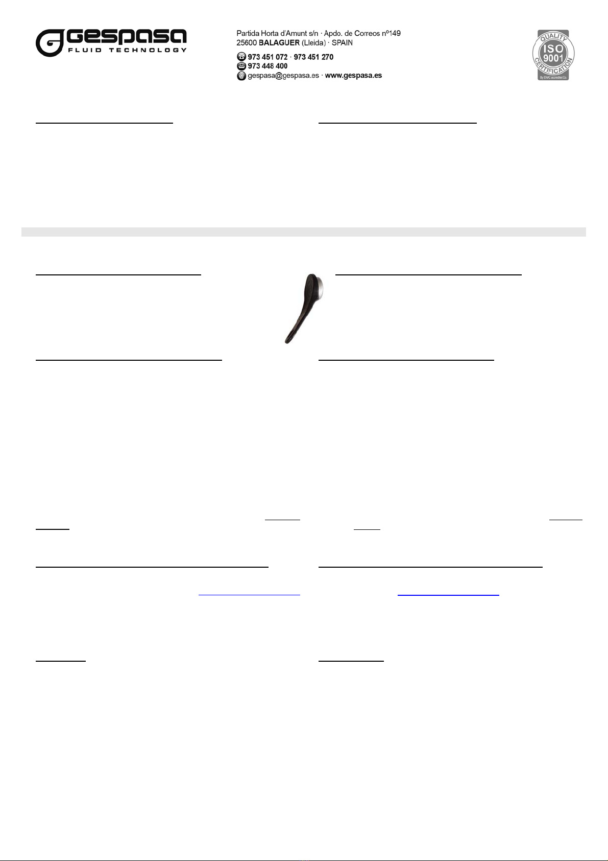
7.2.1. Change of the meter operation mode 7.2.1.Cambio modo funcionamiento del medidor
The meter works by defect without identification. To change the
operation mode of the meter it is required the yellow key that is
supplied along with the pack* of keys. Pass this yellow key through
the key reader of the meter. The kit is automatically configured in
order to be able to work with the identification via key. Take care of
this key, store it somewhere. This key will be used to communicate
the data to the PC when buying, for example, a licence of the
DIESELPLUS management software.
El medidor funciona por defecto sin identificación. Para cambiar el
modo de funcionamiento necesitará la llave amarilla que se
suministra en el pack de llaves. Debe pasar la llave amarilla por el
lector del medidor. El equipo queda automáticamente configurado
para trabajar con identificación por llave. Guarde esta llave amarilla.
Ésta se utilizará como llave para comunicar los datos al PC si
adquiere una licencia para el software de gestión DIESELPLUS.
7.2.2. How to input the iButton keys in the meter 7.2.2. Dar de alta llaves iButton en el medidor
The keys can be used to identify users, vehicles or machines. Las llaves pueden usarse para identificar usuarios, vehículos o
maquinas.
When having a licence for the DIESELPLUS software, input the keys
from the PC. Read the following section 7.2.3. Si dispone de licencia para el software DIESELPLUS deberá dar de alta
las llaves desde el PC. Pase al punto 7.2.3.
When not having any licence, assign the keys from the meter in a
manual way. Follow the below steps: Si no dispone de licencia deberá asignar las llaves manualmente desde
el medidor. Siga los siguientes pasos:
- Enter the Menu 1 of the Supervisor Menu. Press the “TOTAL-CANCEL”
key in a continuous way and at the same time press 10 times the
“RESET-ON/OFF” key (in more or less maximum 10 seconds).
- Entre en el Menú 1 del Menú Supervisor. Para entrar en el menú:
Pulse la tecla “TOTAL-CANCEL” de forma continua y al mismo tiempo
pulse 10 veces la tecla “RESET-ON/OFF. (Realizar en un máximo de 10
segundos).
The display will show “C01”, then press the “TOTAL-CANCEL” key. The
display will show “US 1” (User 1). Put the iButton key in the reader. This
key will be assigned for the User 1. Press again the “TOTAL-CANCEL”
key to continue. The display will show “US 2”. Put another key in the
reader. This will be assigned for the User 2, and so on.
Aparecerá en pantalla "C01" -->Pulse "TOTAL"-->La pantalla mostrará
"US 1" (Usuario 1)--> Sitúe una llave iButton en el lector. Esta llave
quedará asignada al usuario 1--> Pulse "TOTAL"-->"US2"-->Introduzca
otra llave en el lector que quedará asignada al usuario 2 y así
sucesivamente.
Pressing the “RESET-ON/OFF” key at any moment, it is possible to go
out the menu. Apart from entering the users, this menu allows modifying
any user.
Presionando la tecla “RESET” en cualquier momento, se puede salir del
menú. Aparte de dar de alta usuarios, este menú permite modificar
cualquier usuario.
When this process is ended, the meter will work only when passing
one of these entered keys through the meter reader. Al finalizar este proceso el medidor funcionará únicamente si
previamente se pasa una de las llaves dadas de alta por el lector
del medidor.
7.2.3 How to input the iButton keys in the meter from the PC 7.2.3. Dar de alta llaves iButton en el medidor desde el PC
If you have an MGE-110HI communication kit via iButton with
DIESELPLUS licence, you can input the iButton keys from the PC. You
have to activate your licence in the web site www.dieselplus.net/licences
and follow the steps of the documentation that will be sent to you. To
unload the PC information, put the yellow key in the reader; the kit will
make a data exchange. If the process is done correctly, it will appear the
message ‘LOAD’.
Si dispone de un kit de comunicación Ibutton MGE110HI con licencia
DIESELPLUS puede dar de alta las llaves iButton desde el PC. Deberá
activar su licencia en www.dieselplus.net/licences y seguir los pasos en
la documentación que se le enviará. Posteriormente para descargar la
información del PC el medidor se debe situar la llave iButton amarilla en
el lector; el equipo realizará un intercambio de información. Si el proceso
se realiza correctamente, aparecerá el mensaje ‘LOAD’.
If the key is moved or the data are corrupted, it will appear the message
‘Error’. Si se mueve la llave o los datos son corruptos aparecerá el mensaje
‘Error’.
7.2.4. Supply 7.2.4. Suministro
To start a service, it is necessary to be identified via iButton key. If this
key does not belong to any user, the kit will beep repeatedly until the key
is removed from the reader.
Para iniciar un servicio será necesario identificarse con la llave iButton.
Si la llave no pertenece a ningún usuario, el equipo pitará repetidamente
hasta que se retire la llave del lector.
If the key belongs to one user, the kit will beep only once. The display
will show ‘US’ and the user number, which corresponds to the key and at
whom the service litres will be assigned.
Si la llave pertenece a un usuario, el equipo pitará una sola vez y
aparecerá por pantalla ‘US’ y el número de usuario al que pertenece la
llave y, por lo tanto, al que se le asignarán los litros del servicio.
Once the user is identified, the user can start the service, taking the
nozzle down (if you have connection between the nozzle and the meter)
or pressing the “RESET-ON/OFF” key. To end this service, the user can
hang the nozzle up or press the “RESET-ON/OFF” key, regardless of the
way it has been started.
Una vez identificado, el usuario podrá iniciar un servicio descolgando la
pistola (si tenemos conexión entre el colgador de pistola y el medidor) o
pulsando la tecla “RESET-ON/OFF”. Para finalizarlo se puede hacer
colgando la pistola o pulsando la tecla “RESET-ON/OFF”,
independientemente de la manera que se haya iniciado.
If the user does not start the service before 90 seconds, once he is
identified, the meter will delete the identification, and it will be necessary
to identify the user again in order to start the service.
Si, una vez identificado, el usuario no inicia el servicio antes de 90 seg.,
el equipo borrará la identificación y será necesario volver a identificarse
para iniciar el servicio.
If there is no supply during more than 90 seconds, the kit will end the
service and stop the pump. Si durante el servicio se deja de suministrar durante un intervalo de
tiempo mayor a 90 seg., el equipo dará por finalizado el servicio y parará
la bomba.

MGE-110HI INSTRUCTION MANUAL
Manual de instrucciones
6
If there is an electric supply stop during the service, the meter will end it
and display the supplied litres during more than 15 minutes. Finally, it will
be switched off until the electric supply is re-established.
Si durante el servicio hay una interrupción del suministro eléctrico, el
equipo finalizará el servicio y mostrará por pantalla durante más de 15
minutos los litros suministrados. Finalmente se apagará hasta que se
reestablezca el suministro eléctrico.
7.2.5. Litre total by key. How to unload in the PC 7.2.5. Total de litros por llave. Descargar en el PC.
If you have the MGE-110HI communication kit with DIESELPLUS
licence, you can see in the PC the total of the supplied litres by each key
(total per user, vehicle or machine).
Si dispone de kit de comunicación MGE-110HI con licencia
DIESELPLUS, podrá ver en el PC el total de litros suministrados por
cada llave (total por usuario, vehiculo o máquina).
To upload the total of the supplied litres by each key, put the yellow
iButton key in the reader. It will appear the message ‘LOAD’. The data
are saved correctly and now you can upload them in the PC. If the
message ‘Error’ appears, repeat the operation.
Para descargar el total de litros suministrado por cada llave debe situar
la llave iButton amarilla en el lector. Aparecerá el mensaje ‘LOAD’. Los
datos se han grabado correctamente y puede descargarlos en el PC. Si
aparece el mensaje ‘Error’ repita la operación.
8. CONNECTION 8. CONEXIÓN
The meter has 3 connectors: El medidor dispone de tres conectores:
J1: 230 VAC 50/60 Hz connector J1: Conector de alimentación 230 VCA 50/60 Hz
1. Phase 1. Fase
2. Earth 2. Tierra
3. Neutral 3. Neutro
J2: Pump connector J2: Conector de conexión de la bomba
1. Neutral 1. Neutro
2. Phase 2. Fase
3. Earth 3. Tierra
* Maximum motor power: 0.74 kW * Máxima potencia del motor: 0,74 kW
J3: Nozzle and encoder connector J3: Conector de la pistola y el encoder
1. Free nozzle contact 1. Contacto de la pistola libre de potencial
2. Free nozzle contact 2. Contacto de la pistola libre de potencial
3. Encoder Channel A 3. Canal A encoder
4. Encoder Channel B 4. Canal B encoder
5. GND 5. GND
6. 12 VDC outlet 6. Salida alimentación 12 VCC
9. ADVANCED CONFIGURATION 9. CONFIGURACIÓN AVANZADA
The Supervisor mode allows configuring some meter parameters: El modo Supervisor permite configurar determinados parámetros del
medidor:
- The “TOTAL” key is equivalent to say “YES”, to accept, to go into. - Tecla “TOTAL”: equivalente a SÍ, aceptar, entrar.
- The “RESET” key is equivalent to say “NO”, not to accept, to exit
(depending on the selection). - Tecla “RESET” equivalente a NO, no aceptar, salir (dependiendo de la
selección).
9.1. METER CONFIGURATION 9.1. CONFIGURACIÓN DEL CONTADOR
To go into the configuration Menu, follow the below steps: Para entrar dentro del menú de configuración, proceder como sigue:
While pressing the “TOTAL” key and during 10 seconds as maximum, press
ten times the “RESET” key. Mientras se presiona la tecla “TOTAL” y durante un tiempo máximo de 10
segundos, es necesario realizar 10 pulsaciones en la tecla “RESET”.
‘C01’ · Menu 1: It is allowed to enter users with an assigned key (see the
above section 7.2.2).
Apart from entering the users, this menu allows modifying any user.
‘C01’ · Menú 1: Este menú permite dar de alta usuarios. (ver punto 7.2.2).
Aparte de dar de alta usuarios, este menú permite modificar cualquier
usuario.
‘C02’ · Menu 2: When the display shows ‘C02’ and pressing the “TOTAL”
key, it appears the calibration factor of the kit. When released this key, the
display shows again ‘C02’. Pressing the “RESET” key, it is possible to
access the next menu.
‘C02’ · Menú 2: Cuando en la pantalla aparece ‘C02’, y se presiona la tecla
“TOTAL”, aparece el factor de calibración del equipo. Al soltar la tecla, la
pantalla muestra nuevamente ‘C02’ y pulsando la tecla “RESET” se accede
al siguiente menú.
‘C03’ · Menu 3: It is allowed to delete the Total and Partial counters of the
kit. But the user totals are not deleted. The display shows ‘C03’. When
pressing the “TOTAL” key, it is possible to go into the menu, and the display
shows ‘rSt 1’. While pressing the “TOTAL” key, also press the “RESET”
key, and the counters are deleted. When the “TOTAL” key is released, the
display shows ‘C03’. Pressing the “RESET” key, it is possible to access the
next menu.
‘C03 · Menú 3: Este menú permite borrar los contadores Total y Parcial del
equipo. Los totales de los usuarios no se borran. En pantalla aparece ‘C03’.
Presionando la tecla “TOTAL” se entra en el menú y en la pantalla aparece
‘rSt 1’. Mientras se mantiene presionada la tecla “TOTAL”, presionando la
tecla “RESET” se borran los contadores. Al dejar de presionar la tecla
“TOTAL”, aparece en pantalla ‘C03’. Presionando la tecla “RESET” se
accede al siguiente menú.
‘C04’ · Menu 4: The display shows ‘C04’. This option shows the operation
mode of the pulse input (90º, 180º or 1 channel). Pressing the “RESET” key,
the display will show ‘PUL 1’, ‘PUL 2’ or ‘PUL 3’, which means it works with
2 channels and 90º out of phase pulses, with 2 channels and 180º out of
phase pulses or with only one channel, respectively. While pressing the
“RESET” key and if the J4 selection is enabled, and pressing the “TOTAL”
key, it changes from 1 to 2 and to 3, and so on. When the “RESET” key
released, the display shows again ‘C04’. The last chosen option is saved if it
has enabled its PERMANENT memory. When pressing the “TOTAL” key, it
is possible to access the next menu.
‘C04 · Menú 4: En pantalla aparece ‘C04’. Esta opción muestra el modo de
funcionamiento de los impulsos (90º, 180º ó 1 canal). Presionando la tecla
“RESET” la pantalla mostrará ‘PUL 1’, ‘PUL 2’ o ‘PUL 3’, indicando si
funciona con dos canales y los impulsos desfasados 90º, con dos canales y
los impulsos desfasados 180º o con un solo canal, respectivamente.
Mientras se tiene pulsada la tecla “RESET”, si la selección J4 está
habilitada, cuando se presione la tecla “TOTAL” irá cambiando de 1 a 2 y a
3 sucesivamente. Al dejar de presionar la tecla “RESET”, en la pantalla
aparece ‘C04’ y la última opción que se ha escogido quedará grabada en la
memoria no volátil del medidor si la tiene habilitada. Al presionar la tecla
“TOTAL” se accede al siguiente menú.
The kit by default will be configured with PUL 1=90º. For other type of
meters. PUL 2=180º, PUL 3=1 channel. El equipo por defecto estará configurado con PUL 1= 90º. Para otro tipo de
medidores: PUL 2=180º; PUL 3= 1 canal.

MGE-110HI INSTRUCTION MANUAL
Manual de instrucciones
7
‘C05’ · Menu 5: The display shows ‘C05’. When pressing the “TOTAL” key,
this menu makes a test of all the LCD display segments. All the segments
are tested. When pressing the “RESET” key, it is possible to access the
next menu.
‘C05’ · Menú 5: En pantalla aparece ‘C05’. Presionando la tecla “TOTAL”
este menú realiza un test de los segmentos de la pantalla LCD. Se testean
todos los segmentos. Presionando la tecla “RESET”, se accede al siguiente
menú.
‘C06’ · Menu 6: The display shows ‘C06’. When pressing the “TOTAL” key,
it appears the serial number of the meter.
When released this “TOTAL” key, the display shows again ‘C06’, and
pressing the “RESET” key, it is possible to access the next menu.
‘C06’ · Menú 6: En pantalla aparece ‘C06’. Presionando la tecla “TOTAL”
aparece el número de serie del medidor.
Cuando se deja de apretar la tecla “TOTAL”, aparece de nuevo en pantalla
‘C06’. Pulsando la tecla “RESET”, se accede al siguiente menú.
‘C07 · Menu 7: It is allowed to delete all the users and their totals. The
display shows ‘C07’. When pressing the “TOTAL” key, it is possible to
access the menu, and the display shows ‘rSt 2’. While the “TOTAL” key is
pressed, press the “RESET” key, and the users are deleted. When released
the “TOTAL” key, the display shows again ‘C07’. Press the “RESET” key to
access the next menu.
‘C07’ · Menú 7: Este menú permite borrar todos los usuarios y sus totales.
En la pantalla aparece ‘C07’. Presionando la tecla “TOTAL”, se entra dentro
del menú y aparece en pantalla ‘rSt 2’. Mientras se tiene pulsada la tecla
“TOTAL”, al pulsar la tecla “RESET” se borran los usuarios. Al dejar de
pulsar la tecla “TOTAL, aparece de nuevo en pantalla ‘C07’. Para acceder
al siguiente menú, presione la tecla “RESET”.
‘C08’ · Menu 8: The display shows ‘C08’. When pressing the “TOTAL” key,
it shows the software version of the meter. Press the “RESET” key to
access the next menu.
‘C08’ · Menú 8: En pantalla aparece ‘C08’. Si se mantiene pulsada la tecla
“TOTAL”, muestra la versión del software del medidor. Para acceder al
siguiente menú, presione la tecla “RESET”.
‘C09’ · Menu 9: This menu is for the configuration of the parameters from
the factory. It cannot be modified because the meter can be useless. ‘C09’ · Menú 9: Menú para configuración de parámetros de fábrica. No
modificar, ya que puede dejar el medidor inutilizable.
‘C10’ · Menu 10: The display shows ‘C10’. When pressing the “TOTAL”
key, it is possible to go out the Configuration Menu. Pressing the “RESET”
key, it is possible to go to the Menu 1.
‘C10’ · Menú 10: En pantalla aparece ‘C10’. Si se pulsa la tecla “TOTAL”,
se sale del Menú de Configuración. Si se pulsa la tecla “RESET” se vuelve
al Menú 1.
10. METER ASSEMBLY / DISASSEMBLY 10. MONTAJE / DESMONTAJE DEL MEDIDOR
TO GO TO THE GEARS (10) or THE MEASURING CHAMBER PARA ACCEDER A LOS ENGRANAJES (10) o A LA CÁMARA DE
MEDICIÓN
1. Unscrew the screws (21) of the bottom cover and remove them. Remove
the back meter cover (20). Be careful because there are the gears (17) of
the measuring device in its inner.
1. Desenroscar los tornillos (21) de la tapa inferior y sacarlos. Sacar la tapa
trasera del medidor (20). Actuar con precaución ya que en su interior se
encuentran los engranajes (17) del mecanismo de medición.
The magnet gear must be assembled in the shaft that has the point in the
base (placed in the aluminium body). The magnet looks downwards. El engranaje de los imanes se debe montar en el eje que tiene un punto en
la base (situado en el cuerpo de aluminio). Los imanes van hacia abajo.
The reed plate must be assembled following the meter body drawing. The
electronic components must be placed upwards. La placa de los reeds se debe montar igual que el dibujo del cuerpo del
medidor. Los componentes electrónicos se deben posicionar hacia arriba.
2. For its assembly, please follow the above described steps inversely,
taking into account the correct meter body screw, pin and joint placing. 2. Para proceder a su montaje, seguir a la inversa los pasos descritos
teniendo en cuenta la correcta colocación de los tornillos, pasadores y
tórica del cuerpo medidor.
REMARK: Please be careful the magnets must be in the gear
bottom, not visible before closing the cover.
OBSERVACIÓN: Tener en cuenta que los imanes tienen que
estar en la parte inferior de los engranajes, no visibles antes de
cerrar la tapa.
11. MAINTENANCE 11. MANTENIMIENTO
It is possible that some liquids are dried up in the measuring chamber inner,
and block it. If this happens, this meter must be cleaned carefully and when
it is going to be mounted, make sure that it is done correctly. Please follow
the instructions from the above Meter Assembly / Disassembly no. 10
Section.
If the meter is stored for a long time, clean it conscientiously. It will remain
protected and ready for a new starting.
Puede ocurrir que ciertos líquidos se sequen en el interior de la cámara de
medición y la bloqueen. Si esto sucediera, los engranajes deben ser
limpiados con mucho cuidado y, al montarlos de nuevo, asegurarse que se
hace correctamente. Seguir las instrucciones del anterior apartado nº 10
Montaje-Desmontaje.
Si deciden almacenar el medidor por un largo período de tiempo, limpiarlo.
Quedará protegido y listo para una nueva puesta en marcha.
12. REPAIR 12. REPARACIÓN
Please go to the place where you have bought it. There you will be advised
of what the best is. The meters must be cleaned and dried up before its
delivery to be repaired. If the meters are not used with oil or diesel, they
must be cleaned as many times as it is necessary, enclosing a note
indicating the chemical substances that have been supplied with this unit.
When ordering spare parts, make sure that you give the part number and its
correct description. This will guarantee the correct supply of the requested
spare part.
Acudir al punto de venta donde se haya adquirido. Allí se aconsejará lo que
proceda. Los medidores deben ser lavados y secados antes de su envío
para reparar. Si los medidores, por error, no se usan con aceites o gasóleo,
deben aclararse tantas veces como sea necesario y adjuntar una nota que
indique las sustancias químicas que se han suministrado con dicha unidad.
Recordamos que para solicitar un recambio, debe señalar con precisión el
código de la pieza. Esto garantizará el suministro correcto del repuesto
solicitado.
13. GUÍA DE PROBLEMAS
BREAKDOWN POSSIBLE CAUSE SOLUTION
It counts too fast or slow. - non-correct calibration
- air inlet
- blocked gears
- recalibrate the meter (please see Section 6).
- look for and repair possible leaks or air inlets in the system.
- clean or replace the gears.
Low flow - impurities in the measuring chamber - clean the measuring chamber.
The display is not switched on. - there is not electric supply system. - check if the electric supply system gets 230 VAC.
It is supplying, but it does not display
anything.
- impurities in the magnets
- REED problem - disassemble and clean the gears (please see Section 8).
- call the TECHNICAL SERVICE.
Liquid leak - joints in bad state - replace the joints.

MGE-110HI INSTRUCTION MANUAL
Manual de instrucciones
8
13. GUÍA DE PROBLEMAS
AVERÍA POSIBLE CAUSA SOLUCIÓN
Cuenta demasiado rápido o lento. - calibración incorrecta
- toma de aire
- engranajes obstruidos
- recalibrar el medidor (ver apartado 6)
- buscar y reparar posibles fugas o entras de aire en el sistema
- limpiar o reemplazar los engranajes
Bajo caudal - impurezas en la cámara de medición - limpiar la cámara de medición
El display no se enciende. - falta alimentación eléctrica - revisar si llegan 230 VCA.
Sale líquido y no marca. - impurezas imanes
- problema RESET - desmontar y limpiar engranajes (ver apartado 8).
- ponerse en contacto con el SERVICIO TÉCNICO.
Fuga de líquido - juntas en mal estado - reemplazar juntas
14. REPAIR 14. GARANTÍA
1. All the products manufactured by TOT COMERCIAL SA have a
WARRANTY of 12 (twelve) months from their purchase, against any
manufacturing defect.
1. Todos los productos fabricados por TOT COMERCIAL SA tienen una
GARANTÍA de 12 meses desde su compra, contra cualquier defecto de
fabricación.
2. TOT COMERCIAL SA guarantees, in the warranty period, the
change/the devolution of the defective part or product. This material
must be sent with prepaid freight to our factory or any appointed
technical service. After our technical inspection, it will be determined
whether the responsibility is from the manufacturer, the user, the
installer or the delivery.
2. TOT COMERCIAL SA garantiza dentro del período de garantía, el
canje/reposición de la pieza o del producto defectuoso, siempre que el
material sea enviado a portes pagados a nuestra fábrica, o a cualquier
servicio técnico designado. Después de nuestra inspección técnica se
determinará si la responsabilidad es del fabricante, del usuario, del
instalador o del transporte.
3. The warranty does not cover: the inadequate use, the use out of the
specific regulations, the negligence, the corrosion, the abuse, the
manipulation or the wrong installation of the products, a use of non-
original spare parts or not concerning to the specific model, the non-
authorized modifications or interventions, the total or partial instruction
non-fulfilment. All the manufactured and/or commercialized equipment
must be installed according to the manufacturer’s instructions.
3. La garantía no cubre: El uso inadecuado, el uso fuera de la normativa
específica, la negligencia, el abuso, la corrosión, la manipulación o la
incorrecta instalación de los productos, el uso de repuestos no
originales o no correspondientes al modelo específico, las
modificaciones o intervenciones no autorizadas, el incumplimiento total
o parcial de las instrucciones. Todos los equipos fabricados y/o
comercializados por TOT COMERCIAL SA deben ser instalados de
acuerdo con las normas facilitadas por el fabricante.
4. The accessories and the products not manufactured by TOT
COMERCIAL SA are liable for their original manufacturer’s warranty. 4. Los accesorios y productos no fabricados por TOT COMERCIAL SA
están sujetos a la garantía de su fabricante original.
5. Because of the constant innovations and development, TOT
COMERCIAL SA reserves the right to modify the specifications of its
products and publicity, without prior notification.
5. Por las constantes innovaciones y desarrollo, TOT COMERCIAL SA se
reserva el derecho de modificar las especificaciones de sus productos y
publicidad, sin previa notificación.

MGE-110HI INSTRUCTION MANUAL
Manual de instrucciones
9
15. CONFORMITY DECLARATION 15. DECLARACIÓN DE CONFORMIDAD
Manufacturer: Fabricante:
TOT COMERCIAL sa Partida Horta d'Amunt s/n Apartado Correos nº 149 TOT COMERCIAL sa Partida Horta d'Amunt s/n Apartado Correos nº 149
25600 BALAGUER (Lleida) ESPAÑA 25600 BALAGUER (Lleida) SPAIN
STATES: DECLARA:
Under its own responsibility that the following: Bajo su única responsabilidad, que la siguiente máquina:
ELECTRONIC GEAR METER
MEDIDOR ELECTRÓNICO DE ENGRANAJES
Trademark: GESPASA Marca:
GESPASA
Model: MGE-110HI Modelo:
MGE-110HI
It is in accordance with the following Directives of the European
Parliament and the Council: "2006/42/EC of 17 May 2006 on machinery"
and "2004/108/EC of 15 December 2004 on the approximation of the
laws of the Member States relating to electromagnetic compatibility, and it
has been manufactured according to the below technical regulations:
Es conforme con las Directivas del Parlamento Europeo y del Consejo
«2006/42/CE, de 17 de mayo de 2006, relativa a las máquinas» y
«2004/108/CE, de 15 de diciembre de 2004, relativa a la aproximación
de las legislaciones de los Estados miembros en materia de
compatibilidad electromagnética» y ha sido fabricada de acuerdo con las
siguientes normas técnicas:
UNE-EN ISO 12100:2012 Safety of machinery - General principles for
design - Risk assessment and risk
reduction (ISO 12100:2010)
UNE-EN ISO 12100:2012 Seguridad de las máquinas. Principios
generales para el diseño. Evaluación del
riesgo y reducción del riesgo. (ISO
12100:2010)
UNE-EN 55014-1:2008 Electromagnetic compatibility. Require-
ments for household appliances, electric
tools and similar apparatus
Part 1: Emission
UNE-EN 55014-1:2008 Compatibilidad electromagnética. Requisi-
tos para aparatos electrodomésticos, he-
rramientas eléctricas y aparatos análogos
Parte 1: Emisión
UNE-EN 55014-2/A1:2002 Electromagnetic compatibility. Require-
ments for household appliances, electric
tools and similar apparatus
Part 2: Immunity. Product family standard
UNE-EN 55014-2/A1:2002 Compatibilidad electromagnética. Requisi-
tos para aparatos electrodomésticos, he-
rramientas eléctricas y aparatos análogos
Parte 2: Inmunidad. Norma de familia de
productos
- IP-55 protection - Grado de protección IP-55
The pumps, meters and nozzles as nearly machines must not be on
service while the machine, where these are placed, does not meet the
2006/42/EC (Machines) Directive requirements.
- Las bombas, medidores y las pistolas como casi máquinas no deben
ser puestas en servicio mientras la máquina donde va ubicada no haya
sido declarada de conformidad con los requisitos de la directiva
2006/42/CE (Máquinas).
- This Declaration will lose its validity in case that any modification is
made without the explicit manufacturer's consent.
- La presente declaración perderá su validez en caso que se realicen
modificaciones en la máquina sin el consentimiento explícito del
fabricante.
BALAGUER (Lleida), October 2016 BALAGUER (Lleida), octubre 2016
Andrés Pané
Andrés Pané
This manual suits for next models
1
Table of contents
Other Gespasa Measuring Instrument manuals