GESTRA NRGT 26-1S User manual

1
EN
English
Level Transmitter
NRGT 26-1
NRGT 26-1S
Original Installation Instructions
810213-11

2
Contents
Page
Important notes
Usage for the intended purpose...............................................................................................................4
Function..................................................................................................................................................4
Safety note..............................................................................................................................................4
Directives and standards
VdTÜV Bulletin "Water Monitoring 100"...................................................................................................5
Approvals for Marine Applications ...........................................................................................................5
LV (Low Voltage) Directive and EMC (Electromagnetic Compatibility)........................................................5
ATEX (Atmosphère Explosible) .................................................................................................................5
UL/cUL (CSA) Approval ............................................................................................................................5
Note on the Declaration of Conformity / Declaration by the Manufacturer ..........................................5
Technical data
NRGT 26-1, NRGT 26-1S.........................................................................................................................6
Scope of supply ....................................................................................................................................7
Name plate/marking ...............................................................................................................................8
Installation
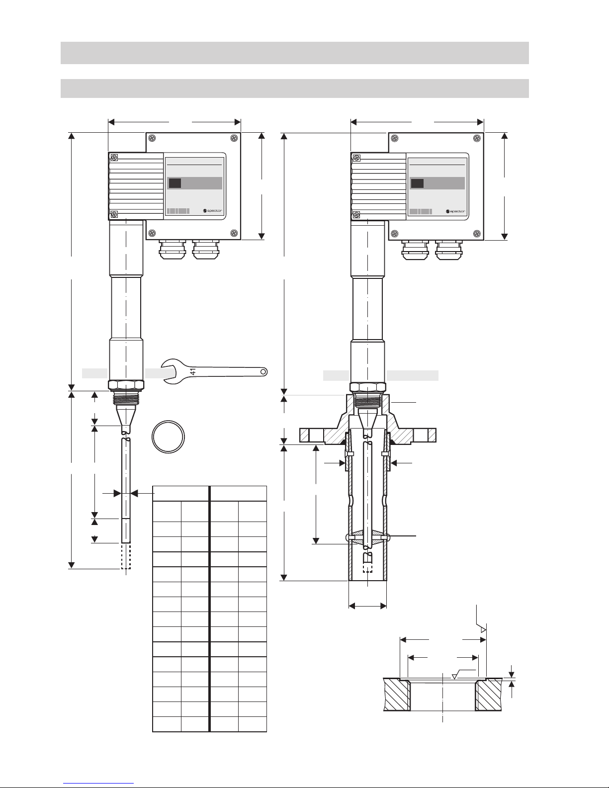
Dimensions NRGT 26-1, NRGT 26-1S....................................................................................................10
NRGT 26-1............................................................................................................................................11
NRGT 26-1S..........................................................................................................................................11
Key .......................................................................................................................................................11
Tools.....................................................................................................................................................11
Examples of installation
NRGT 26-1............................................................................................................................................12
Key .......................................................................................................................................................13
Electrical connection
NRGT 26-1, NRGT 26-1S.......................................................................................................................14
Connection of level transmitter..............................................................................................................15
Connecting the NRGT 26-1, NRGT 26-1S...............................................................................................15
Key .......................................................................................................................................................15
Tools.....................................................................................................................................................15
Wiring diagram for level transmitter NRGT 26-1, NRGT 26-1S ...............................................................16
Connecting level transmitter NRGT 26-.. with supply voltage 24 V AC/DC ..............................................16
Connecting level transmitter NRGT 26-.. with supply voltage 115 / 230 V AC.........................................16
Actual value output ...............................................................................................................................16

3
Contents
Page
- continued -
Basic settings
Factory setting NRGT 26-1....................................................................................................................17
Factory setting NRGT 26-1S..................................................................................................................17
Establishing active measuring range (control range)..............................................................................17
Commissioning procedure
Applying supply voltage.........................................................................................................................18
Adjusting lower end of measuring range ..............................................................................................18
Adjusting upper end of measuring range...............................................................................................18
Troubleshooting
Indication, diagnosis and remedy ..........................................................................................................19
Replacing electronic module ................................................................................................................20
Maintenance
Safety note............................................................................................................................................21
Cleaning the electrode rod ....................................................................................................................21
Removing and disposing of the level transmitter
Removing and disposing of level transmitter NRGT 26-1, NRGT 26-1S ..................................................21

4
Important notes
Usage for the intended purpose
The level transmitters NRGT 26-1 and NRGT 26-1S are used for continuous level monitoring in steam
boilers and (pressurized) hot-water installations or in condensate and feedwater tanks.
In conjunction with the level switch NRS 2-.. and the level controller NRR 2-.. the transmitter can be
used as water level controller with MIN/MAX alarm.
The level transmitter is designed for use in conjunction with the following level switches/controllers:
NRS 2-50, NRS 2-51, NRR 2-50, NRR 2-51, NRR 2-52 and NRR 2-53.
The level transmitter can be used in electrically conductive and non-conductive fluids.
Function
The level transmitter NRGT 26-1 is a compact-type system consisting of a level measuring electrode
and an electronic module integrated in the terminal box.
The level transmitter NRGT 26-1 works according to the capacitance measurement principle and
translates the level changes into a level-dependent current signal of 4-20 mA, with the length of the
electrode rod determining the measuring range.
The level transmitter is installed inside steam boilers, vessels or in an external level pot. If the elec-
trode is installed inside the boiler or vessel, a protection tube provided on side ensures correct func-
tioning (see section Examples of installation (page 12).
The level transmitter can be installed together with one GESTRA level electrode for water level limiting
or for high-level alarm in a single protection tube or an external level pot.
Safety note
Danger
When loosening the level transmitter steam or hot water might escape!
This presents the risk of severe scalding all over the body!
It is therefore essential not to dismantle the level transmitter unless the boiler pressure is
verified to be 0 bar.
The level transmitter becomes hot during operation.
Risk of severe burns to hands and arms.
Before carrying out installation and maintenance work make sure that the equipment is
cold.
The terminal strip of the level transmitter is live during operation.
This presents the danger of electric shock!
Cut off power supply before mounting or removing the housing cover!
Attention
The name plate specifies the technical features of the equipment. Do not commission or
operate any item of equipment that does not bear its specific name plate.
The equipment must only be installed, wired and commissioned by qualified and competent staff.
Retrofitting and maintenance work must only be performed by qualified staff who - through adequate
training - have achieved a recognised level of competence.

5
The equipment meets the requirements of Directives: UL 508 and CSA C22.2 No. 14-13, Standards for
Industrial Control Equipment. File E243189.
Directives and standards
VdTÜV Bulletin "Water Monitoring 100"
Approvals for Marine Applications
The level transmitter NRGT 26-1S is approved for marine applications.
The level transmitter NRGT 26-1 is type approved acc. to VdTÜV Bulletin "Water Level 100" if used in
combination with the following level switches / controllers: NRS 2-50, NRS 2-51, NRR 2-50, NRR 2-51,
NRR 2-52 and NRR 2-53.
The VdTÜV Bulletin "Wasserstand (=Water Level) 100" specifies the requirements made on water level
control and limiting equipment for boilers.
ATEX (Atmosphère Explosible)
According to the European Directive 2014/34/EU the equipment must not be used in explosion risk areas.
UL/cUL (CSA) Approval
LV (Low Voltage) Directive and EMC (Electromagnetic Compatibility)
The level transmitter NRGT 26-1 meets the requirements of the Low Voltage Directive 2014/35/EU and
the EMC Directive 2014/30/EU.
For details on the conformity of our equipment according to the European Directives see our Declaration
of Conformity or our Declaration of Manufacturer.
The current Declaration of Conformity and Declaration of Manufacturer are available in the Internet under
www.gestra.com documents
or can be requested from us.
Note on the Declaration of Conformity / Declaration by the Manufacturer

6
NRGT 26-1, NRGT 26-1S
Technical data
Service pressure
PN 40, 32 bar at 238°C
Mechanical connection
NRGT 26-1: Screwed G ¾ A, ISO 228
NRGT 26-1S: Flange DN 50, PN 40, DIN EN 1092-01
Materials
Screw-in body: 1.4571, X6CrNiMoTi17-12-2
Electrode rod insulation: PTFE
Terminal box: 3.2161 G AlSi8Cu3
NRGT 26-1S: Flange 1.0460 P250GH
NRGT 26-1S: Spacer disc: PTFE
NRGT 26-1
Length of installation
at 238°C
373 477 583 688 794 899 1004 1110
Measuring range 300 400 500 600 700 800 900 1000
Length of installation
at 238°C
1214 1319 1423 1528 1636 2156
Measuring range 1100 1200 1300 1400 1500 2000
NRGT 26-1S
Length of installation
at 238°C
316 420 526 631 737 842 947 1053
Measuring range 275 420 526 575 675 737 875 975
Length of installation
at 238°C
1157 1262 1366 1471 1579 2099
Measuring range 1075 1175 1275 1375 1475 1975
Weight
NRGT 26-1: approx. 1.8 kg
NRGT 26-1S: approx. 8.0 kg
Electronic module
Supply voltage
24 V AC/DC
AC +/– 20%
DC +10 / –45%
115 V +/– 10%, 50/60 Hz (option)
230 V +/– 10 %, 50/60 Hz (option)
Power consumption
3 VA at 24 V DC
5 VA at 24, 115, 230 V AC

7
Technical data
NRGT 26-1, NRGT 26-1S
Fuse
external slow-blow 0.5 A
internal thermal fuse Tmax = 102°C
Sensitivity of response
Range 1: Water ≥ 20 µS/cm
Range 2: Water ≥ 0.5 µS/cm
Range 3: Fuel oil EL εr2,3
Output
Actual value 4 – 20 mA, level proportional. Electrically insulated, max. load 500 Ω
Indicators and adjusters
2 red LEDs for signalling "Level 0 %" or "Level 100" within the measuring range
1 green LED for signalling “Level between 0 % and 100 %” of measuring range
1 code switch for setting the measuring range
2 adjustable resistors for small-percentage adjustment of the measuring range
2 terminal lugs for voltage measurement
Electrical connection
2 cable glands with integral cable clamp M20 x 1.5
Screw-type terminal strip with 2 and 3 terminals, detachable, conductor size 1.5 mm2
Protection
IP 65 to DIN EN 60529
Max. admissible ambient temperature
Max. 70 °C
Storage and transport temperature
– 40 to + 80 °C
Approvals:
TÜV certificate VdTÜV Bulletin "Water Level 100"
Requirements made on water level limiting & control equipment.
Type approval no. TÜV · WR · XX-391, XX-425, XX-426, XX-427
(see name plate)
UL/cUL (CSA) Approval The equipment meets the requirements of Directives: UL 508 and CSA C22.2
No. 14-13, Standards for Industrial Control Equipment. File E243189.
Marine applications DNV A-13857, KR HMB 06190-MS002, NK TA11016M, BV 10617/CO
CCS HBT 0742 1062-1, RINA ELE 407609CS, GL 992499-96 HH;
LR 98/20074 (E2)
Scope of supply
NRGT 26-1
1 Level transmitter NRGT 26-1
1 Joint ring 27 x 32, form D, DIN 7603, 2.4068, bright annealed
1 Installation manual
NRGT 26-1S (for marine applications)
1 Level transmitter NRGT 26-1S with flange DN 50, PN 40, DIN EN 1092-01
1 Installation manual
- continued -
- continued -

8
Technical data
Name plate/marking
Equipment designation,
pressure rating
Fig. 1
End connection,
material number
Pressure/temperature rating
Power rating
Measuring range
Actual value output
CE Marking
Manufacturer
Safety note
Disposal note
PN 40PN 40
PN 40PN 40
IP 65IP 65
32 bar (464psi)
238°C (460°F)
32 bar (464psi)
238°C (460°F)
Tamb
70°C
(158°F)
Tamb
70°C
(158°F)
Münchener Str.77
D-28215 Bremen
Münchener Str.77
D-28215 Bremen
Type approval no.
- continued -
TÜV · WR · XX-391, -425, -426, -427

9
Installation
Note
The level transmitter NRGT 26-1 can be installed together with one GESTRA level elec-
trode for water level limiting or for high-level alarm in a single protection tube or exter-
nal level pot (inside diameter 100 m). Fig. 5 - 8. If the level limiting electrode is installed
inside the vessel, it must be at least 40 mm away from the upper vent hole.
For the approval of the boiler standpipe the relevant regulations must be considered.
Refer to pages 12 and 13 for typical installation examples.
The angle of inclination of the electrode must not exceed 45°, with the length of the
electrode being limited to 688 mm. Fig. 9
The seating surfaces of the standpipe or the flange provided on the vessel must be
accurately machined, see Fig. 4.
Do not bend electrode tip when mounting.
Do not subject electrode to physical shocks.
Use only the supplied joint ring. NRGT 26-1: 27 x 32, form D, DIN 7603, 2.4068,
bright annealed
Do not lag transmitter body above the hexagonal section.
Do not insulate transmitter thread with hemp or PTFE tape!
Do not apply conductive paste or grease to the transmitter thread!
Observe the minimum withdrawal distance when installing the transmitter!
Observe the specified tightening torque.
Do not cut the electrode rod.
Attention

10
GESTRA Steam Systems
GESTRA
Installation
Dimensions NRGT 26-1,NRGT 26-1S
0
9
8
Fig. 3
NRGT 26-1S
a
b = 68
173173
Ra 3.2
0.5
∅ 33
Ra 12.5
Fig. 4
140
∅48.5
∅ 42.5
336
62
7
- continued -
3
4
Screwed G ¾ A,
ISO 228
GESTRA Steam Systems
GESTRA
Fig. 2
NRGT 26-1
173
b = 68
336
a
NRGT 26-1 NRGT 26-1S
1 2 3 4
373 300 316 275
477 400 420 375
583 500 526 475
688 600 631 575
794 700 737 675
899 800 842 775
1004 900 947 875
1110 1000 1053 975
1214 1100 1157 1075
1319 1200 1262 1175
1423 1300 1366 1275
1528 1400 1471 1375
1636 1500 1579 1475
2156 2000 2099 1975
5
7
6
140
37
26
Screwed G ¾ A,
ISO 228
12∅ 15

11
Installation
NRGT 26-1S
1. Check seating surfaces and place joint ring onto the connecting standpipe.
2. Put flange 8with level transmitter onto connecting standpipe and bolt them together.
Tighten bolts in diagonally opposite pairs.
NRGT 26-1
1. Check seating surfaces. Fig. 4
2. Place supplied joint ring 5onto seating surface of the threaded standpipe or flange. Fig. 4
3. Apply a light smear of heat resistant silicone grease (e.g. WINIX®2150) to electrode thread 6.
4. Screw level transmitter into threaded standpipe or flange and tighten with an open-end spanner
A. F. 41 mm. The torque required when cold is 160 Nm.
Tools
Open-end spanner A. F. 41, DIN 3110, ISO 3318
Key
1 + 3Max. length of installation at 238 °C
2 + 4Measuring range
5Joint ring 27 x 32, form D, DIN 7603, 2.4068, bright annealed
6Thread G ¾ A to ISO 228 of transmitter
7Thermal insulation, provided on site, d = 20 mm (outside of thermal insulation of steam boiler)
8Flange DN 50, PN 40, DIN EN 1092-01
9Protection tube
0Spacer disc
aCable glands
- continued -

12
Examples of installation
NRGT 26-1
Fig. 5 Protection tube (provided on site) for installation
inside the boiler
Fig. 6 Protection tube (provided on site)
for installation inside the boiler
Fig. 7 Protection tube (provided on site) for installation
inside the boiler and in combination with other
GESTRA equipment
2
20
DN 50
G ¾
∅20
∅ 20
≤ 90°
i
e
b
c
d
f
g
k
l
20
∅
20
≥ 10
DN 50
G ¾
∅ 20
≤3000
e
b
c
f
g
k
l
≤ 90°
Fig. 8 External level pot
DN 20
DN 20
Centre distance
≤ 20
G ¾
DN 20
≤20
b
f
e
k
n
d
190
4
DN 100
24.5 24.5
∅20
G ¾
∅ 20
≤ 90°
≤3000
G ¾
b
k
h
c
j
m
d
f
i
20
≥14
e

13
Examples of installation
bFlange PN 40, DN 50, DIN EN 1092-01 (for one electrode)
Flange PN 40, DN 100, DIN EN 1092-01 (for electrode combination)
cFor the approval of the boiler standpipe with connecting flange the relevant regulations
must be considered.
dVent hole ∅20 mm
eHigh water HW
fElectrode rod
gProtection tube DN 80 (in France according to AFAQ ≥ DN 100)
hProtection tube DN 100
iDistance between electrode rod and protection tube ≥ 14 mm
jDistance between electrode tip (NRG 1..-50 or NRG 1...-51) ≥ 14 mm (creepage distances
and clearances)
kLow water NW
lReducer DIN 2616-2, K-88.9x3.2-42.4 x 2.6 W
mReducer DIN 2616-2, K-114.3x3.6-48.3 x 2.9 W
nLevel pot ≥ DN 80
Key
- continued -
NRGT 26-1 - continued -
DN 100
45°
max.688
d
Tube e.g. 33.7 x 3.2 dd
120
Fig. 9 Inclined installation,
e. g. in steam boilers
b

14
GESTRA SteamSystems
GESTRA
Electrical connection
NRGT 26-1,NRGT 26-1S
Fig. 10
v
Fig. 11 Shown without cover plate
o
r
p
s
q
t
u
y
1
2
3
4
6
7
8
9
0
5
12 345
wx
A z
B
C
D

15
A self-locking fixing nut Cconnects the terminal box to the electrode part. Before establishing the
electrical connection you can turn the terminal box through max. +/- 180° into the desired direction
(cable gland).
Electrical connection
Connection of level transmitter
1. Unscrew housing screws oand remove housing cover p. Fig. 10
2. Remove terminal strips zand Afrom circuit board.
3. Strip off approx. 40 mm of cable insulation coating and remove approx. 5 mm of conductor end
insulation.
4. Loosen cable glands q. If the equipment is supplied with 24 V pull control cable through one of the
cable glands. Seal off the unused cable gland (protection IP 65). If the equipment is supplied with
115 / 230 V pull the power cable through the right cable gland and the control cable through the left.
5. Connect the individual cables according to the wiring diagram to terminal strip zand A.
6. Attach terminal strips zand Ato the circuit board.
7. Tighten cable glands q.
7. Mount cover pand fasten cover screws o.
Connecting the NRGT 26-1,NRGT 26-1S
oCover screws (cross-recess head M4)
pCover
qCable glands M 20 x 1.5
rSelector switch for measuring range
sLED "Level 0 %"
tLED "Level > 0 %, < 100 %
uLED "Level 100 %"
vTerminal lugs for voltage measurement
(between 0 - 7 V, level proportional)
wPotentiometer for lower measuring point
xPotentiometer for upper measuring point
yThermal fuse TMAX 102 °C
zTerminal strip for supply voltage
ATerminal strip for actual-value output
BConnection for functional earth
CFixing nut for terminal box
DFixing screw for electronic circuit board
Key
Attention
The following relocations of cables with basic insulation are not permissible:
Mains and control cables in low voltage areas.
- continued -
Screwdriver, size 1
Screwdriver, size 2.5, completely insulated according to DIN VDE 0680-01
Tools

16
Electrical connection
Wiring diagram for level transmitter NRGT 26-1, NRGT 26-1S
Fig. 12 + –
(L) (N)
DC
Supply Thermal
fuse
4-20 mA
max. load.
500 Ω
Earthing
screw
in housing
PE
S1 Disconnecting switch
Fuse
Connecting level transmitter NRGT 26-.. with supply voltage 115 / 230 V AC
An external slow-blow fuse 0.5 A must be provided for the level transmitter. To connect the
voltage supply use a multi-core control cable with a min. conductor size 0.5 mm2. To connect the
actual value output use screened multi-core control cable with a min. conductor size 0.5 mm2,
e. g. LiYCY 2 x 0.5 mm2, max. length: 100 m.
Install a disconnector for all poles. Make sure it is easily accessible and in the close proximity of the
equipment (EN 61010-1). Mark this disconnecting switch as isolating device for the level transmitter.
Connecting level transmitter NRGT 26-.. with supply voltage 24 V AC/DC
An external slow-blow fuse 0.5 A must be provided for the level transmitter. For the connection use
screened multi-core control cable with a min. conductor size 0.5 mm2, e. g. LiYCY 4 x 0.5 mm2, max.
length 100 m.
For the power supply of the level transmitter use a safety power supply unit (PSU), e.g. Siemens SITOP
PSU100C 24V/0.6A, which must provide a level of isolation against voltages that at least meets the
requirements for double or reinforced insulation as per DIN EN 50178 or DIN EN 61010-1 or
DIN EN 60730-1 or DIN EN 60950 (electrically protective separation).
24V AC/DC
optional 115/230 V AC
- continued -
NRGT 26-1
NRGT 26-1S
F1
Any item of equipment that you want to connect to the terminals for the actual-value output 4 - 20 mA
must be certified to have at least double or reinforced isolation according to DIN EN 50178 or
DIN EN 61010-1 or DIN EN 60730-1 or DIN EN 60950 (safe electrical isolation) between the current
loop and live parts of the equipment that are not supplied with safety extra-low voltage (SELV).
Make sure that the connecting cable is segregated and runs separately from power cables. Please
observe the max. load of 500 ohm.
Actual value output

17
Basic settings
Factory setting NRGT 26-1
The level transmitter features the following factory set default values:
Measuring range1300 mm: Switch rposition 4, water ≥ 20 µS/cm
Measuring range 1400 mm to 1700 mm: Switch rposition 4, water ≥ 20 µS/cm
Measuring range 1800 mm to 1500 mm: Switch rposition 4, water ≥ 20 µS/cm
Measuring range 1600 mm to 2000 mm: Switch rposition 5, water ≥ 20 µS/cm
XSelected (active) measuring range [mm]
24Measuring range [mm] = xxx % see Fig. 2 and 3
ELower end of measuring range, adjustable
FUpper end of measuring range, adjustable
5Water, conductivity ≥ 20 µS/cm
6Water, conductivity ≥ 25 µS/cm
7Fuel oil EL, dielectric constant εr2,3
4
4
4
4
4
4
4
4
4
4
4
4
4
4
4
5
5
5
5
5
100
200
300
400
500
600
700
800
900
1000
1100
1200
1300
1400
1500
1600
1700
1800
1900
2000
3
3
3
4
4
4
4
4
5
5
5
5
5
5
5
5
6
6
6
6
3
3
3
3
3
3
3
3
3
3
3
3
3
3
3
3
3
4
4
4
Lower measuring point
26
Attention
If Xis clearly smaller than 24set switch rone step back.
Establishing active measuring range (control range)
Within the measuring range of the transmitter you can establish the active control range.
Use switch rto establish the length of the active measuring range. Switch rsee Fig. 11.
Factory setting NRGT 26-1S
The level transmitter features the following factory set default values:
Measuring range1275 mm: Switch rposition 4, water ≥ 20 µS/cm
Measuring range 1375 mm to 1675 mm: Switch rposition 4, water ≥ 20 µS/cm
Measuring range 1775 mm to 1475 mm: Switch rposition 4, water ≥ 20 µS/cm
Measuring range 1575 mm to 1975 mm: Switch rposition 5, water ≥ 20 µS/cm
Fig. 13
37
X567
2
rF
E
4X

18
Commissioning procedure
Danger
The terminal strip of the level transmitter is live during operation.
This presents the danger of electric shock!
Cut off power supply before mounting or removing the housing cover!
Use only a completely insulated screwdriver according to VDE 0680 for setting the
measuring points.
1. Unscrew cover screws oand remove cover p. Fig. 10
2. Lower liquid level until the lower end of the measuring range is reached.
3. Raise the pressure in the steam boiler or vessel until the service pressure is reached.
4. Turn potentiometer wto the left until the red LED slights up.
5. Turn potentiometer wto the right until only the green LED tlights up.
The lower end of the measuring range is now adjusted.
Adjusting lower end of measuring range
1. Fill tank and wait for 30 seconds (internal attenuation).
2. Turn potentiometer xto the right until only the red LED ulights up.
3. Turn potentiometer xto the left until the green LED tlights up.
4. Turn potentiometer xto the right until the green LED tgoes out.
The upper end of the measuring range is now adjusted.
5. Mount cover pand fasten cover screws o.
Adjusting upper end of measuring range
When adjusting the measuring range when the system is cold, the adjusted measuring
points will shift with rising temperature as a result of the longitudinal expansion of the
electrode rod. Correct the settings accordingly.
If a higher accuracy (for 0 % = 4 mA and 100 % = 20 mA) than ± 0.5 mA is required,
measure the level-proportional current at terminals 1 üand 2 äin order to establish
more accurate settings.
Note
Please check that the level transmitter is wired in accordance with the wiring diagram (Fig. 12
page 16) and switch on mains voltage. When the electrode tip is exposed the LED is illuminated s.
Fig. 11
Applying supply voltage

19
Attention
Before carrying out the fault diagnosis please check:
Supply voltage:
Is the level transmitter supplied with the mains voltage specified on the name plate?
Wiring:
Is the wiring in accordance with the wiring diagram?
Troubleshooting
Indication, diagnosis and remedy
Malfunctions
Equipment does not work accurately
Error Remedy
The transmitter was installed without a protection
tube. The protection tube is required because it serves
as reference electrode.
Install a protection tube.
The vent hole in the protection tube does not exist, is
obstructed or flooded. Check protection tube and, if necessary, provide vent hole.
The isolating valves of the external level pot (optional)
are closed. Open isolating valve.
The desired lower measuring point is outside the
measuring range of the transmitter.
The transmitter is too short.
Install a sufficiently long level transmitter.
The adjustment of the measuring range is wrong. Correct switch rsettings.
See Basic Settings
The electrode rod is covered with dirt deposits. Remove level transmitter and clean the electrode tip with
a wet cloth.
The transmitter is defective. Actual value output
(terminals 1 and 2) > 20 mA. Fig. 12
Replace level transmitter.
Equipment fails to work
Error Remedy
Power failure. Switch on supply voltage.
Check all electrical connections.
Thermal fuse ydefective.
Discard and replace defective thermal fuse. Stock code
# 052433.Check ambient temperature, make sure that it
does not exceed 70° C.
The earth connection to the vessel is interrupted.
Clean seating surfaces and screw in the level transmit-
ter together with the joint ring 27 x 32, form D, DIN 7603
(made from 2.4068), bright annealed. Do not insulate the
level transmitter with hemp or PTFE tape!
Electronic circuit board defective Exchange the electronic insert.

20
Troubleshooting
1. Unscrew cover screws oand remove housing cover p.
2. Pull electrode wires from terminal lugs on module. Detach terminals strips zA.
3. Undo the functional earth Bconnection.
4. Unscrew the fixing screws Dfor the electronic module and take out the module.
The module is available as spare part.
Stock code # NRGT 26-1 NRGT 26-1S
321317 230 V AC
321340 115 V AC
321354 24 V AC/DC
321319 230 V AC
321342 115 V AC
321355 24 V AC/DC
5. Install the new electronic module in reverse order.
Note
After replacing the electronic module please re-commission the equipment.
Replacing electronic module
- continued -
Other manuals for NRGT 26-1S
1
This manual suits for next models
1
Table of contents
Other GESTRA Transmitter manuals

GESTRA
GESTRA NRS 2-1 Quick guide

GESTRA
GESTRA TRV 5-40 User manual

GESTRA
GESTRA LRGT 16-2 User manual

GESTRA
GESTRA TRV 5-60 Installation instructions

GESTRA
GESTRA NRGT 26-2 User manual

GESTRA
GESTRA NRGT 26-2 User manual

GESTRA
GESTRA NRGT 26-2 User manual

GESTRA
GESTRA LRGT 16-3n User manual

GESTRA
GESTRA LRGT 16-3 User manual

GESTRA
GESTRA LRGT 16-3 Installation instructions