Lucoro Broadcast FMTX50RBRX User manual

FMTX50RBRX
Transmitter with integrated Baseband (multiplex)
PLL 8 . – 108 MHz Rebroadcast Receiver
User Manual
WARNING!
This Transmitter is capable of generating extremely high RF
potential. Touching internal parts, or the connected antenna
system, will cause serious RF burns. Antenna systems should be
installed such that exposure by any person to RF fields cannot
exceed safe limits. The permitted limits vary from country to
country. Expert advice should be sought about the safe
installation of this transmission system.
RISK OF FIRE!
RF (Radio Frequency) energy could cause ignition of combustible
surfaces during fault conditions. Installation should be left to
qualified personnel. RF can cause burns to skin. Ensure antenna
systems and feeder cables are not situated near, or could fall
onto, any combustible surface.

IMPORTANT!
Always reduce the RF Output power to minimum before changing
the transmission frequency. Once the new frequency is active,
slowly increase the RF output power control to provide the
required power output level.
WARNING!
Never operate this device without a suitable 50 ohm load
connected to the RF OUTPUT socket, or without a suitably
installed and matched antenna system connected. Although the
output of this transmitter is protected against antenna load
faults, MIS-OPERATION MAY RESULT IN DAMAGE NOT COVERED
BY ANY WARRANTY.
IMPORTANT!
Correct operation of the cooling fans in this product is vital to
reliable continuous operation. Schedule bi-annual maintenance
checks. We strongly advise the use of a standby transmitter
system for use during maintenance events or fault conditions, to
prevent prolonged breaks in transmission.
IMPORTANT!
When cycling the power off, then on, ensure that the transmitter
is off for at least 10 seconds before re-applying power, to allow
the internal circuits time to fully reset. Failure to do so may result
in no RF output (PLL failsafe mode).
Consideration should be given to fitting a suitably rated UPS if
power interruptions are likely. Similarly, telemetry reset of power
may be advisable for transmitters in remote areas, or having
restricted access arrangements.

The FMTX50RBRX is an FM broadcast transmitter with an integrated
baseband PLL 8 . – 108 MHz rebroadcast receiver integrated in a
highly compact product.
At the heart of the FMTX50RBRX is a high quality PLL modulator, and
the RF Power Amplifier uses the latest high-gain Enhancement Mode
MOSFET device, achieving new levels of efficiency and reliability.
TTL remote monitoring and switching allows the FMTX50RBRX to be
easily integrated into automated back-up applications. An audio silence
alarm, plus remote RDS TA control are also provided.
These instructions should be read in full before the transmitter is
operated.
The safety and operating instructions should be retained for future
reference.
All warnings on the transmitter and in the operating instructions
should be adhered to.
All operation and user instructions should be followed.
Use of this device into a radiating antenna requires a valid licence from
a Spectrum Management Authority in most countries.
Use of this device as part of a transmission system, or combined
transmission system not specified by the manufacturer, may require
further testing to ensure that it remains compliant with the essential
requirements and other relevant provisions of current EU Low Voltage,
EMC and Radio Equipment Directives. Approval and clearance from the
Spectrum Management Authority may also be required.
In
troduction
Before operating

Installation must adhere to safety regulations and the requirements of
the relevant authorities. We recommend that at least two people are
present during installation. Keep a file containing installation
instructions and plans, including details of the transmission system
(antennas, feeders, filters, etc) and operating instructions for all
equipment at the transmission site at all times. Display posters
detailing first aid treatment and treatment for electrical shock, along
with telephone numbers for contacting the emergency services in the
event of personal injury.
Ensure antenna system lightning strike protection is in place.
To reduce the risk of electrical shock, do not remove the cover, or any
screws. There are no user serviceable parts inside; refer servicing to
qualified personnel.
Do not expose this appliance to rain or moisture. The transmitter
should not be used near water. Care should be taken so that objects
do not fall - and liquids are not spilled - into the enclosure through
openings.
To reduce the risk of fire, always replace fuses with the same type and
rating.
The transmitter should be mounted into a well-ventilated standard 19
inch equipment rack, using slide supports. It should be situated so that
its location or position does not interfere with its proper ventilation.
The transmitter should be situated away from heat sources.
The transmitter should be connected to a power supply only of the
type described in the operating instructions or as marked on the unit.
Precautions should be taken so that the grounding or polarisation of
this appliance is not defeated.
The unit should be cleaned only as recommended by the
manufacturer.
The transmitter should be serviced by qualified service personnel if it
does not appear to operate normally, exhibits a marked change in
performance, has been subjected to shock, damage, moisture, or if
foreign objects have ingressed.
The user should not attempt to service the transmitter beyond that
which is described in the Operating Instructions. All other servicing
should be referred to qualified service personnel.

This appliance may become warm under normal operating conditions.
Recycle according to WEEE regulations.
1. SYSTEM Status LED. Green indicates correct operation, red indicates
a system error requiring urgent further investigation.
2. DOWN Push-button. Press this control to navigate the LCD menu.
3. ENTER Push-button. Press this control to navigate the LCD menu.
4. UP Push-button. Press this control to navigate the LCD menu.
5. AF MON BNC connector for monitoring of the input to the
modulator (baseband MPX spectrum).
6. RF MON BNC connector for monitoring of the RF output. Output
level will be the RF output level attenuated by approximately 40dB. Not
to be used for measurement of harmonics.
. RF OUT 'N' Socket. Connect a matched, pre-tested antenna system
with a return loss of >14dB to this socket. Ensure all parts of the feeder
and antenna system are rated for 100W or above.
Controls and Connectors

8. RF ADJ Use a suitable trimmer tool to adjust the RF output power
level, (RF FWD on the display). Never set to above the 50W maximum
rated output power.
9. REMOTE 9-pin D-sub Female. Remote control and monitor inputs
and outputs are available on this connector:
Pin 1. Reflected Power Alarm. TTL logic low during normal
operation. Floats high to indicate a high level of reflected power
(critical antenna mis-match) has been detected.
Pin 2. Forward Power alarm. TTL logic low during normal
operation. Floats high to indicate loss of RF output .
Pin 3. RX failure alarm. TTL logic low during normal operation.
Floats high to indicate loss of parent station.
Pin 4. Temperature alarm. TTL logic low during normal
operation. Floats high to indicate over-temperature condition
has occurred.
Pin 9. RF Mute Control. Supplying between 5 and 12V this pin to
(with reference to chassis ground potential) will mute the RF
output. Primarily used in automated changeover systems.
Pin 6, , 8 GND connection, at chassis earth potential.
The above ‘Open Collector’ outputs are capable of operation up to 50V
and sinking a current of 5mA maximum. The normally high, (ie. ‘pull
low’ upon alarm condition) provides inherent ‘power failure’ or ‘cable
connection failure’ signalling.
10. RX IN. ‘N’ Socket. Connect the receiving antenna to this input.
11. AC POWER. Connect a power lead with an IEC C13 connector (and
a 3 amp fuse in the plug or at the distribution panel) to this socket. Two
T2 amp (time delay) fuses are fitted within this connector’s Fuse carrier.
12. EARTH. Grounding connection point (M4 stud and bolt).

Connect a suitable rated test load to the RF OUPUT socket before
connecting the unit to mains power. IMPORTANT! FAILURE TO DO SO
MAY RESULT IN DAMAGE NOT COVERED BY WARRANTY.
Power-up the unit and reduce the output power (using the rear panel
RF OUTPUT POWER ADJUST control) to the lowest level.
Using the front panel display and buttons, set the desired transmission
frequency.
Power down the unit, wait a few seconds and, whilst pressing
ENTER for 5 seconds, power up the unit. After a short while, the
currently set transmission frequency will appear on the display
with the rest of the display blanked-out. Use the UP and DOWN
buttons to select the desired frequency. Press ENTER to store.
The new frequency will flash rapidly to indicate that it is now
stored. The unit will begin its boot process and, after a few
seconds the display will return to normal mode, and the
transmitter will begin broadcasting.
Using the front panel display and buttons, set the desired reception
frequency.
Power down the unit, wait a few seconds and, whilst pressing UP
and DOWN for 5 seconds, power up the unit. After a short while,
the currently set receiver frequency will appear on the display,
with the rest of the display blanked-out. Use the UP and DOWN
buttons to select the desired frequency. Press ENTER to store.
The new frequency will flash rapidly to indicate that it is now
stored. The unit will begin its boot process and, after a few
seconds the display will return to normal mode, and the
transmitter will begin broadcasting.
The deviation level of the rebroadcast should match that of the parent
station. Note that, like all rebroadcast transmissions, the level of the
higher frequency subcarriers, particularly the RDS, will be slightly lower,
due to IF filtering and distance fade. Most parent stations that supply
relay sites have their RDS injection level set slightly higher, to
compensate for this.
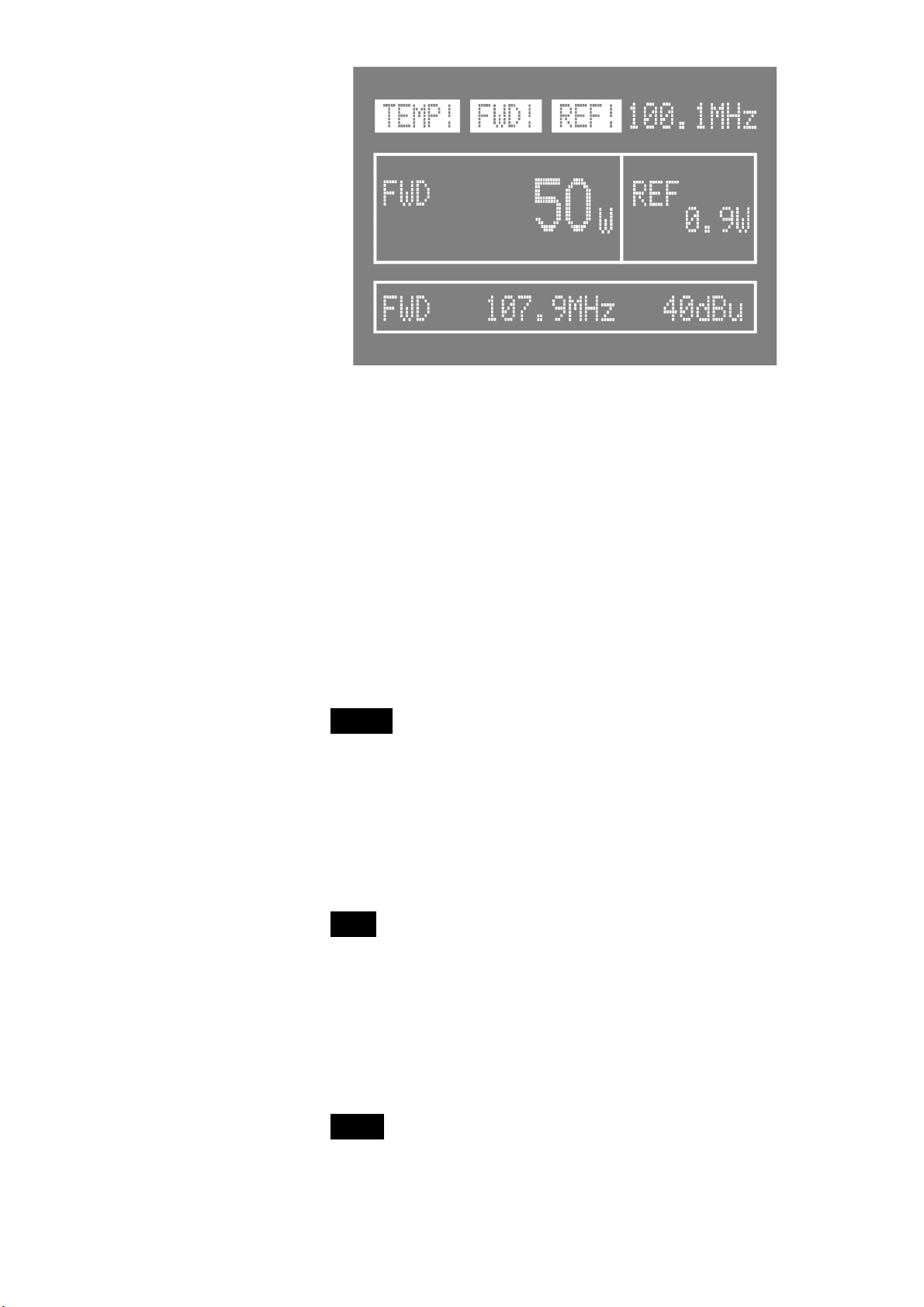
The optimum received signal level is 50dBu. Lower levels
will may contain noise which could cause non-compliance
with regulatory spectral occupancy limits. Likewise,
received signal levels higher than 50dBu will over-load
Installation

the receiver’s front-end circuitry, again causing non-
compliance of the spectral occupancy.
NOTE: If changing the transmission frequency, upon installation, or at
any time in the future, check the deviation levels using a calibrated
deviation test receiver. If the level is too high or low, adjust it using the
following procedure:
Disconnect power to the transmitter. Connect a suitable rated test
load to the RF OUPUT socket before re-connecting the unit to mains
power. IMPORTANT! FAILURE TO DO SO MAY RESULT IN DAMAGE NOT
COVERED BY WARRANTY.
Power-up the unit and reduce the output power (using the rear panel
RF OUTPUT POWER ADJUST control) to the lowest level. Disconnect the
power; there are high voltages and high RF levels inside the transmitter
when AC supply is applied. Remove the lid, and locate the multi-turn
trimmer adjustment control labelled ‘DEV’ on the PCB. This can be
found on the main (central) PCB. Using a suitable tool, carefully turn
the control clockwise (for more deviation) or ant-clockwise (for less
deviation).
Once all settings are correct, power down the unit. Disconnect the test
load and connect to the antenna. Power up the unit and increase the
RF Power (using the rear panel RF ADJ control) to the desired level, not
exceeding 50W.
The FMTX50RBRX is designed for continuous reliable transmission,
however the fans must be periodically checked for correct operation
and free airflow.
The front panel display shows the transmission frequency, forward
power level ( FWD ), reflected power level ( REF ), the receiver (RX)
frequency, and the received signal strength level in dBu.
Opera
tion

Correct operation is confirmed by a front panel green STATUS LED.
Should this turn red, the transmission system may shut down its RF
output and will, in any case, require URGENT attention.
The LCD display shows all main parameters so no further menus are
provided or required (except frequency settings detailed above).
During normal operation, therefore, the menu buttons do not have
any function.
The following are LCD display fault indicators and their meaning:
TEMP! The system is running too hot and has shut down the RF
output as a safety precaution. Check the fans for correct
operation. Also check the antenna system, including all cabling
(and/or filters and/or combiners where fitted) for correct
operation. The FWD! indicator (see below) will also show and the
standby transmission system (where used) will have activated
(TTL control).
REF!! The system has detected a fault in the antenna system
and has shut down the RF output as a safety precaution. Check
the antenna system, including all cabling (and/or filters and/or
combiners where fitted) for correct operation. The FWD!
indicator (see below) will also show and the standby
transmission system (where used) will have activated (TTL
control).
FWD! The system has detected there is no forward power. This
may be due to one or both of the above symptoms, due to a PLL
failure, or due to excessive power setting. The standby
transmission system (where used) will have activated (TTL
control).

Ensure air vents and internal air tunnels are kept free from dust during
operation.
The cooling fans should be replaced after 40,000 hours of cumulative
operation. This life rating is for guidance only and is subject to ideal
environmental operating conditions. Replace any fan that fails or
becomes slow or noisy, immediately. Replacement fan assemblies with
wiring loom and mating connector are available from the
manufacturer. It is recommended that replacement work must be
carried out by the manufacturer or an approved agent.

EC Declaration of Conformity to R&TTE Directive 1999/5/EC
We, Lucoro Broadcast
Clay Pit Lane
Roecliffe
York
YO51 9FS
hereby take sole responsibility to confirm that the product:
FMTX50
(and versions thereof with M and RBRX suffix)
which this declaration refers to, conforms to all applicable
requirements of EU Directive 2014/53/EU and is CE marked
accordingly:
Low Voltage Directive 2014/35/EU:
IEC 60950-1:2005/A2:2013
Safety Requirements for equipment < 600V
EMC Directive 2014/30/EU:
ETSI EN301 489-53 v1.1.0 (ETSI EN301 489-1 v2.1.1
ERM/EMC for Radio Equipment
Specific Conditions for FM Transmitters (Part 11)
Radio Equipment Directive 2014/53/EU:
ETSI EN302018-2 v2.1.1
Transmitting Equipment for FM Radio Broadcasting service
The following operation conditions and installation arrangements have
to be presumed:
(i) According to Operating Instruction Manual
(ii) Connected lead lengths of 2 metres or less
M. O’Rorke, Director
September 2020

RF:
Frequency range 8 .5 to 108.00MHz
Frequency stability Better than ±200Hz
Output power 15 - 50W
Harmonic & spurious output - 5dBc typical
AM Noise <0.5% @ ±40kHz deviation
THD <0.15%@ ± 5KHz deviation
RF output connector ‘N’ type (F)
Monitoring:
RF BNC (F) -40dB 50 ohms
MPX BNC (F) 1V P-P 10K ohms
Receiver:
Frequency range 8 .5 – 108.0MHz
RX input connector ‘N’ type (F)
Power Supply:
Input AC 100V to 250V (50/60 Hz)
Consumption (maximum RF output) 125W (230V 50Hz)
Mechanical:
Size (mm) 2U 88 (H) x 482 (W) x 290 (D)
Weight 5kg
Temperature 0ºC to +42ºC
Humidity 95% (relative non-condensing)
We reserve the right to alter specifications without notice. E&OE.
Technical Specifications

WEEE - Waste Electrical and Electronic Equipment
The equipment that you bought has required the extraction and use of
natural resources for its production. It may contain hazardous
substances that could impact health and the environment.
In order to avoid the dissemination of those substances in our
environment and to diminish the pressure on the natural resources,
we encourage you to use the appropriate take-back systems. Those
systems will reuse or recycle most of the materials of your end life
equipment in a sound way.
The crossed-out wheeled bin symbol invites you to use those systems.
If you need more information on the collection, reuse and recycling
systems, please contact your local or regional waste administration.
IMPORTANT!
NO REPRESENTATIONS OR WARRANTIES, EITHER EXPRESS OR IMPLIED,
OF MERCHANTABILITY, FITNESS FOR A PARTICULAR PURPOSE OR OF
ANY OTHER NATURE ARE MADE WITH RESPECT TO THIS PRODUCT. Do
not misconstrue any information as our recommendation to use any
product, process, or equipment in conflict with any regulatory authority
or patent.
Ensure compliance with all applicable safety requirements when
installing or using this equipment, and operate in accordance with local
laws governing the use of radio transmission equipment.
No part of this document may be reproduced or transmitted, in any
form, by any means, without prior written consent of the Lucoro
Broadcast.

Lucoro Broadcast shall not be liable for any direct, indirect, incidental,
consequential or other damage or loss alleged in connection with the
supply or use of this product.
The information contained in this document is subject to change
without notice. Lucoro Broadcast makes no warranty of any kind with
respect to this information. Lucoro Broadcast specifically disclaims the
implied warranty of merchantability and fitness for a particular
purpose.
Lucoro Broadcast
Clay Pit Lane
Roecliffe
York
YO51 9FS
Telephone 01423 313550
Telephone (International) +44 1423 313550
Enquiries: sales@lucorobroadcast.com
Table of contents
Other Lucoro Broadcast Transmitter manuals

Lucoro Broadcast
Lucoro Broadcast FMTX100 User manual

Lucoro Broadcast
Lucoro Broadcast FMTX50M User manual

Lucoro Broadcast
Lucoro Broadcast FMTX100RBRX User manual

Lucoro Broadcast
Lucoro Broadcast FMTX250 User manual

Lucoro Broadcast
Lucoro Broadcast FMTX1 User manual

Lucoro Broadcast
Lucoro Broadcast FMTX100M User manual

Lucoro Broadcast
Lucoro Broadcast FMTX250M User manual
Popular Transmitter manuals by other brands

Ramsey Electronics
Ramsey Electronics MR6 user manual

JUMO
JUMO Wtrans B operating manual

Linear
Linear 1050 installation instructions

AIRTRONICS
AIRTRONICS Vanguard FM 4 Channel instruction manual

Status Instruments
Status Instruments SEM310 user guide

Polar Electro
Polar Electro Transmitter Nike+ user manual