GEV LBU 1336 User manual

Installation LBU 1336, Abb. A
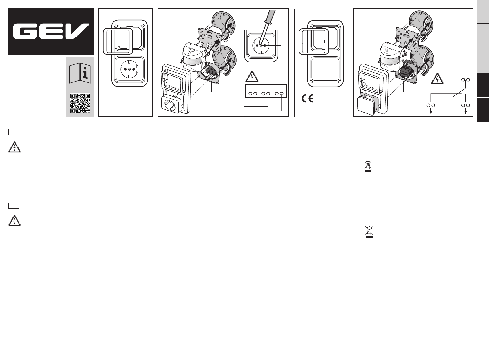
Schrauben Sie die Abdeckung von der Steckdose ab und
verdrahten die Netzanschlussleitung gemäß Schaltbild
(Abb. A3). Setzen Sie die Steckdose in die Unterputzdose
ein (Abb. A) und befestigen Sie mit den beiden seitlichen
Schrauben (Abb. A1). Bei der Montage eines GEV Unterputz
Bewegungsmelders (nicht im Lieferumfang) gehen Sie bitte
entsprechend der Montageanleitung des Melders vor und
nutzen den beiliegenden Abdeckrahmen zur Befestigung.
Setzen Sie den Rahmen auf und schrauben die
Steckdosenabdeckung fest (Abb. A2). Schalten Sie die
Stromkreissicherung wieder ein.
2-fach Abdeckrahmen mit Steckdose LBU 1336 / 2-fach Abdeckrahmen mit Aus-/Wechselschalter LBU 1343 Setzen Sie zuerst den Rahmen und dann den Fixierrahmen auf
den Schalter. Befestigen Sie jetzt die Flächenwippe auf den
Schalter. Schalten Sie die Stromkreissicherung wieder ein.
Recycling-Hinweise
Dieses Gerät darf nicht mit dem unsortierten Hausmüll
entsorgt werden. Besitzer von Altgeräten sind gesetzlich
dazu verpflichtet, dieses Gerät fachgerecht zu entsorgen.
Informationen erhalten Sie von Ihrer Stadt- bzw.
Gemeindeverwaltung.
Installation LBU 1343, Abb. B
Entfernen Sie die Flächenwippe von dem Schalter und
verdrahten die Netzanschlussleitung gemäß Schaltbild
(Abb. B2). Setzen Sie den Schalter in die Unterputzdose ein
(Abb. B) und befestigen ihn mit den beiden seitlichen
Schrauben (Abb. B1). Bei der Montage eines GEV Unterputz
Bewegungsmelders (nicht im Lieferumfang) gehen Sie bitte
entsprechend der Montageanleitung des Melders vor und
nutzen den beiliegenden Abdeckrahmen zur Befestigung.
Technische und optische Änderungen ohne Ankündigung vorbehalten.
Sicherheitshinweise
Die Montage darf nur von einem Fachmann
unter Berücksichtigung der landesüblichen
Installationsvorschriften ausgeführt werden. Es darf nur
im spannungsfreiem Zustand gearbeitet werden, dazu unbedingt
die Stromkreissicherung abschalten. Überprüfen Sie, ob die
Anschlussleitung spannungsfrei ist! Bei Schäden, die durch
Nichtbeachtung dieser Bedienungsanleitung verursacht werden,
erlischt der Garantieanspruch! Für Folgeschäden übernehmen
wir keine Haftung! Bei Sach- oder Personenschäden, die
durch unsachgemäße Handhabung oder Nichtbeachtung der
Sicherheitshinweise verursacht werden, übernehmen wir keine
Haftung. In solchen Fällen erlischt jeder Garantieanspruch. Aus
Sicherheits- und Zulassungsgründen ist das eigenmächtige
Umbauen und/oder Verändern des Gerätes nicht gestattet.
Technische Daten
Netzanschluss 230 V ~, 50 Hz
Nennstrom LBU 1336 max. 16 A
Nennstrom LBU 1343 max. 10 A
Anschlussklemmen bis 2 x 2,5 mm²
Abmessungen
Unterputz-Schalterdose bis Ø 68 mm
Abdeckrahmen B 82 x H 153 x T 11 mm
Safety instructions
This device may only be installed by a technician
in accordance with the applicable regulations.The
electrical power supply and the circuit protection must
be switched o during the entire installation process.
Please check that the connection cable is disconnected!
Under no circumstances does the warranty cover damage
resulting from failure to observe these instructions. Nor do we
accept liability for any indirect damage. Similarly, we can accept
no liability for any material damage or bodily injury caused by
mishandling or failure to observe the safety instructions. In these
cases, no warranty claim may be made. In addition, for safety
and compliance reasons, you are not authorised to dismantle
and/or alter the house light in any way.
Installation LBU 1336, Fig. A
Remove the cover from the socket and connect the mains
connection cable as shown in the wiring diagram (Fig. A3).
Place the socket in the recessed-mounted box (Fig. A) and
attach with the two lateral screws (Fig. A1). When installing
a GEV recessed-mounted motion detector (not supplied),
follow the detector’s installation instructions and use the
supplied cover frame to attach it.
First place the frame and then the cover on the socket, then
tighten the central screw (Fig. A2). Switch the circuit protection
back on.
Installation LBU 1343, Fig. B
Remove the rocker plate from the switch and connect the
mains connection cable as shown in the wiring diagram (Fig.
Double cover frame with socket LBU 1336 / Double cover frame with o/change-over switch LBU 1343
B2). Place the switch in the recessed-mounted box (Fig. B) and
attach with the two lateral screws (Fig. B1). When installing
a GEV recessed-mounted motion detector (not supplied),
follow the detector’s installation instructions and use the
supplied cover frame to attach it.
First place the frame and then the fixing frame onto the switch.
Then attach the rocker plate to the switch. Switch the circuit
protection back on.
Recycling instructions
This device may not be disposed of with unsorted
household waste. Owners of old devices are required
by law to dispose of this device correctly. Contact your
local town council for further information.
Technical and design features may be subject to change.
Technical information
Mains connection 230 V ~, 50 Hz
Rated current LBU 1336 max. 16 A
Rated current LBU 1343 max. 10 A
Terminals up to 2 x 2.5 mm²
Measurements
Recessed-mounted switchbox up to Ø 68 mm
Cover frame W 82 x H 153 x D 11 mm
Des modifications techniques et esthétiques peuvent être apportées sans préavis.
Cadre double avec prise LBU 1336 / Cadre double avec interrupteur va-et-vient LBU 1343
Consignes de sécurité
L’installation de ce produit doit impérativement être
eectuée par un spécialiste et conformément aux
prescriptions en vigueur. L’alimentation électrique
doit obligatoirement être coupée (fusible secteur déconnecté)
pendant toute la durée de l’installation.Le câble d’alimentation
ne doit être soumis à aucune tension.La garantie ne couvre en
aucun cas les dommages dus à un non-respect de la présente
notice. Nous déclinons par ailleurs toute responsabilité quant
aux éventuels dommages indirects. De même, nous ne pourrons
être tenus pour responsables des éventuels dommages
matériels ou blessures corporelles résultant de manipulations
inappropriées ou du non-respect des consignes de sécurité.
Dans de tels cas de figure, tout recours en garantie sera exclu.
En outre, pour des raisons de sécurité et de conformité, tout
démontage et toute modification de l’éclairage d’extérieur sont
interdits.
Installation LBU 1336, fig. A
Dévissez le cache de la prise et raccordez le câble d’alimentation
conformément au schéma électrique (fig. A3). Placez la prise
dans le boîtier encastré (fig. A) et fixez-la à l’aide des deux
vis latérales (fig. A1). Pour le montage du détecteur de
mouvement à encastrer de GEV (non fourni), reportez-vous
aux instructions de montage du détecteur et fixez-le au
moyen du cadre inclus.
Positionnez d’abord le cadre puis le cache sur la prise et insérez
la vis centrale (fig. A2). Remettez en place le fusible secteur.
Installation LBU 1343, fig. B
Ôtez le bouton à bascule de l’interrupteur et raccordez le câble
d’alimentation conformément au schéma électrique (fig. B2).
Placez l’interrupteur dans le boîtier encastré (fig. B) et fixez-le
à l’aide des deux vis latérales (fig. B1). Pour le montage du
détecteur de mouvement à encastrer de GEV (non fourni),
reportez-vous aux instructions de montage du détecteur et
fixez-le au moyen du cadre inclus.
Positionnez d’abord le cadre puis le cadre de fixation
de l’interrupteur. Fixez ensuite le bouton à bascule sur
l’interrupteur. Remettez en place le fusible secteur.
Remarques concernant le recyclage
Cet appareil ne doit en aucun cas être jeté avec les
ordures ménagères. Les propriétaires d’équipements
électriques ou électroniques usagés ont en eet
l’obligation légale de les déposer dans un centre de
collecte sélective. Informez-vous sur les possibilités de
recyclage auprès de votre municipalité.your local town council
for further information.
Caractéristiques techniques
Raccordement au réseau 230 V ~, 50 Hz
Courant nominal LBU 1336 16 A max.
Courant nominal LBU 1343 10 A max.
Bornes de raccordement jusqu’à 2 x 2,5 mm²
Dimensions du boîtier à encastrer jusqu’à Ø 68 mm
Cadre l 82 x h 153 x p 11 mm
GB
FR
DE
DEGBFRITPL
A
LBU 1336
1
2
PE
N
L
3
Typ: LBU 001336
B
LBU 1343
1
L
2
Typ: LBU 001343
297 mm
210 mm
14UW12 MA00142103
Indicazioni di sicurezza
Il montaggio deve essere svolto esclusivamente da
personale specializzato, nel pieno rispetto delle norme
di installazione locali. Tale operazione deve essere
eettuata soltanto previa interruzione dell’alimentazione di
corrente del circuito elettrico. Verificare che il cavo sia privo di
tensione!. In caso di danni derivanti dalla mancata osservanza
delle istruzioni per l’uso, la garanzia decade. Il produttore non
si assume alcuna responsabilità in merito a tali danni. Inoltre,
il produttore non si assume alcuna responsabilità in caso di
danni a cose o persone conseguenti a un utilizzo inadeguato del
dispositivo o alla mancata osservanza delle norme di sicurezza.
Nei suddetti casi decade ogni diritto di garanzia.
Per motivi relativi a sicurezza e certificazioni, non è consentito
apportare variazioni e/o modifiche arbitrarie alla lampada.
Installazione LBU 1336, Fig. A
Svitare la copertura dalla presa di corrente e collegare il cavo
di alimentazione elettrica come indicato nello schema (Fig. A3).
Inserire la presa nella piastra da incasso (Fig. A) e fissarla con
le due viti laterali (Fig. A1). Per il montaggio del rilevatore di
movimento incassato GEV (non contenuto nella confezione),
seguire le relative istruzioni di montaggio e utilizzare la
piastra di copertura fornita in dotazione per il fissaggio.
Inserire prima la cornice e quindi la copertura sulla presa,
dopodiché serrare la vite centrale (Fig. A2). Attivare nuovamente
l’interruttore automatico del circuito elettrico.
Doppia piastra di copertura con presa di corrente LBU 1336 / Doppia piastra di copertura con interruttore/commutatore LBU 1343
Installazione LBU 1343, Fig. B
Rimuovere l’interruttore a bilico dal commutatore e collegare
il cavo di alimentazione come indicato nello schema
(Fig. B2). Inserire il commutatore nella piastra da incasso
(Fig. B) e fissarlo con le due viti laterali (Fig. B1). Per il
montaggio del rilevatore di movimento incassato GEV (non
contenuto nella confezione), seguire le relative istruzioni
di montaggio e utilizzare la piastra di copertura fornita in
dotazione per il fissaggio.
Inserire prima la piastra di copertura e quindi la piastra di
fissaggio sull’interruttore. Fissare l’interruttore a bilico sul
commutatore. Attivare nuovamente l’interruttore automatico del
circuito elettrico.
Indicazioni per il riciclaggio
Questo dispositivo non deve essere smaltito come rifiuto
indierenziato. Chi possiede un vecchio dispositivo è
vincolato per legge allo smaltimento conformemente alle
normative in vigore. Per ulteriori informazioni rivolgersi
all’amministrazione comunale.
L‘azienda si riserva il diritto di apportare modifiche tecniche ed estetiche senza preavviso.
Dati tecnici
Collegamento di rete 230 V ~, 50 Hz
Corrente nominale LBU 1336 max. 16 A
Corrente nominale LBU 1343 max. 10 A
Morsetti max. 2 x 2,5 mm²
Dimensioni Piastra da incasso Ø 68 mm max
Piastra di copertura L 82 x A 153 x P 11 mm
297 mm
roszczenia gwarancyjne wygasają. Z przyczyn związanych z
bezpieczeństwem i dopuszczeniami technicznymi, samowolne
przeróbki lub modyfikacje urządzenia są niedozwolone.
Instalacja urządzenia LBU 1336, rys. A
Odkręć osłonę gniazda wtykowego i wykonaj połączenia
sieciowe zgodnie ze schematem (rys. A3). Włóż gniazdo
wtykowe do puszki podtynkowej (rys. A) i zamocuj ją za
pomocą dwóch bocznych śrub (rys. A1). Podczas montażu
podtynkowej czujki ruchu GEV (nieobjęta dostawą)
postępuj zgodnie z instrukcją montażu czujki, używając do
zamocowania dołączoną ramę maskującą. Zamontuj ramę i
przykręć z powrotem osłonę gniazda wtykowego (rys. A2). Na
koniec włącz z powrotem zabezpieczenie obwodu prądowego.
Podwójna rama maskująca z gniazdem wtykowym LBU 1336 / podwójna rama osłaniająca z wyłącznikiem/przełącznikiem LBU 1343
Zamontuj ramę, ramę mocującą i dźwigienkę przełącznika. Na
koniec włącz z powrotem zabezpieczenie obwodu prądowego.
Uwagi dotyczące recyklingu
Niniejszego urządzenia nie wolno usuwać razem z
niesortowanymi odpadami domowymi. Posiadacze
zużytego sprzętu są ustawowo zobowiązani do zapewnienia
prawidłowej utylizacji urządzeń. Odpowiednie informacje
można uzyskać u odpowiednich władz miejskich lub gminnych.
Instalacja urządzenia LBU 1343, rys. B
Zdejmij dźwigienkę przełącznika i wykonaj połączenia sieciowe
zgodnie ze schematem (rys. B2). Włóż przełącznik do puszki
podtynkowej (rys. B) i zamocuj go za pomocą dwóch bocznych
śrub (rys. B1). Podczas montażu podtynkowej czujki ruchu
GEV (nieobjęta dostawą) postępuj zgodnie z instrukcją
montażu czujki, używając do zamocowania dołączoną ramę
maskującą.
Zastrzega się możliwość wprowadzania zmian technicznych i wizualnych bez wcześniejszego powiadomienia.
Uwagi dotyczące bezpieczeństwa
Montaż może być wykonywany wyłącznie przez
specjalistę, przy przestrzeganiu obowiązujących
w danym kraju przepisów dotyczących instalacji
elektrycznych. Dozwolona jest wyłącznie praca przy
odłączonym napięciu. W tym celu należy bezwzględnie
rozłączyć bezpiecznik obwodu prądowego. Sprawdź, czy w
przewodzie podłączeniowym nie ma napięcia! W przypadku
szkód spowodowanych nieprzestrzeganiem niniejszej instrukcji
obsługi gwarancja wygasa! Za szkody wtórne nie przyjmujemy
żadnej odpowiedzialności! Nie przyjmujemy odpowiedzialności
w przypadku szkód rzeczowych i obrażeń ciała spowodowanych
nieumiejętnym postępowaniem lub niestosowaniem się do uwag
związanych z bezpieczeństwem. W takich przypadkach wszelkie
Dane techniczne
Przyłącze zasilania sieciowego 230 V ~, 50 Hz
Prąd znamionowy LBU 1336 maks. 16 A
Prąd znamionowy LBU 1343 maks. 10 A
Zaciski przyłączeniowe do 2 x 2,5mm²
Wymiary
Podtynkowe gniazdo przełącznikowe do Ø 68mm
Rama maskująca (szer. x wys. x głęb.) 82 x 153 x 11 mm
DEGBFRITPL
210 mm
PL
IT
Max. 14 Ct./Min aus dem deutschen Festnetz.
Mobil max. 42 Ct./Min.
International calls may vary.
GEV GmbH
Heidehofweg 16
25499 Tangstedt
Deutschland
www.gev.de
Hotline: +49 (0)180/59 58 555
A
LBU 1336
1
2
PE
N
L
3
Typ: LBU 001336
B
LBU 1343
1
L
2
Typ: LBU 001343
This manual suits for next models
3
Other GEV Accessories manuals


