10
Please read carefully and retain! In buying this item you have
opted for a high-quality FlammEx product. Please read these user
instructions carefully to ensure the device is used correctly. Keep
them in a safe place for future reference. Use this product only
as intended (as set out in the user instructions). Any changes
or modifications to the product or painting it will result in loss
of warranty.
Product description
The retrofittable radio module sends and receives alarm signals in
conjunction with other radio-networking FlammEx products if they
also have an FMF 3545. As soon as an alarm via the network terminal
emits, the radio module sends the alarm via radio to all radio modules
in its radio group. This process involves the radio modules that are
in range forwarding an alarm message within the respective radio
group once. This alarm message even bypasses transmission paths
that are particularly long, such as from the basement to the top floor
via the ground floor, for example. When the alarm is no longer active
at the original triggering device, the radio modules cancel the alarm
after a short time (up to approximately 30 seconds). Up to 30 radio
modules with smoke detectors can be assigned to a radio group.
Up to eight independent radio groups can be programmed so that
modules do not interfere with each other within blocks of flats, for
example. The radio modules assigned to the same radio group must
only be located within one building. It is not permitted to install some
of the radio modules in neighbouring buildings.
Operation/testing
Each detector/radio module that receives a radio signal directly from
the signal origin in the same radio group forwards this signal forwards
once automatically. To avoid data collision, the signal is forwarded
only when the radio channel is free. Each detector sending a signal
acknowledges that the signal has been forwarded by emitting 3-4
short sounds at intervals of approximately five seconds. When the
channel is free again, the next detector/radio module forwards the
signal and acknowledges it, and so on. When a battery is drained, this
is displayed locally on the host device, as described in its instructions.
In addition, the radio module automatically measures the battery
approximately every 20 minutes. The drained threshold value is set
to approximately 6.9 V, so that the message will be sent only after the
fault message is displayed by the host device itself. Each detector
sending a battery signal acknowledges that the signal has been
forwarded by emitting 3-4 short sounds at intervals of approximately
five seconds. When the channel is free again, the next detector/
radio module forwards the signal and acknowledges it, and so on.
Note: Follow the instructions for the host device.
Programming/commissioning
Note: We recommend programming the radio modules
before installing the equipment on the ceiling.
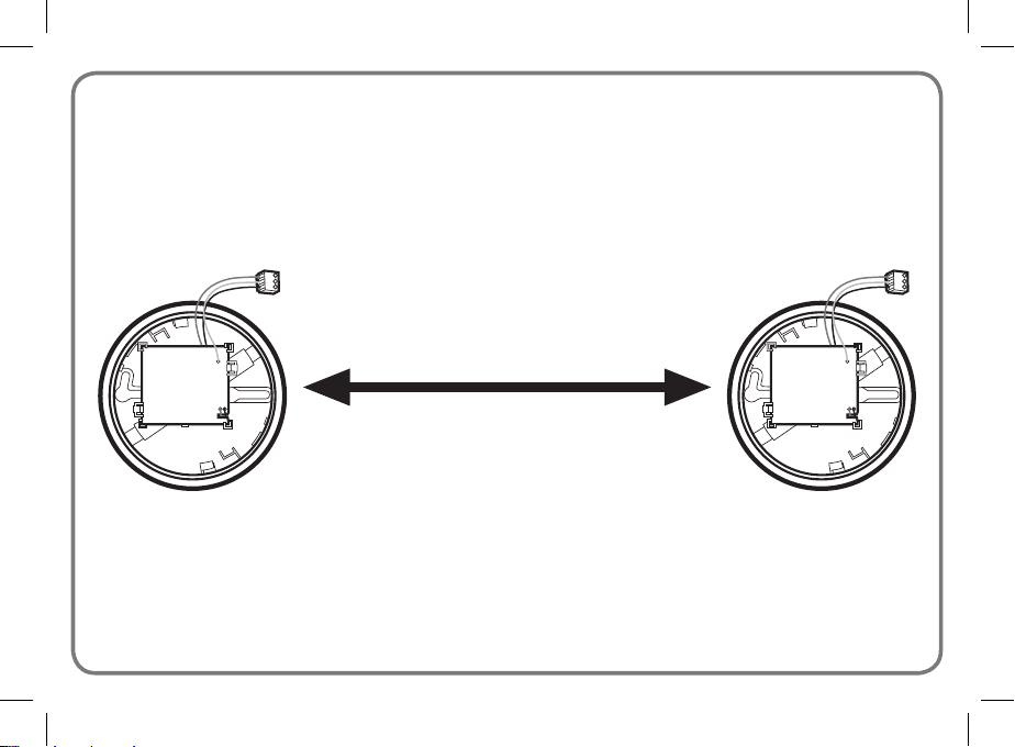
At any one time, activate only the two radio modules that are to be
programmed and not every module simultaneously. To ensure that the
other radio modules remain deactivated, remove the three-pin terminal
of the radio module (Fig. 1.3) from the host device or disconnect the
battery for all other modules.
• The radio module and the host device share the same battery.
Sharing the battery means that the battery life is reduced.
• Close the battery compartment of the host device. The red LED
on the host device flashes briefly approximately every 45 seconds
to indicate that the battery is fitted correctly.
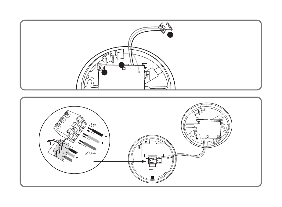
• Connect the radio module to the host device. To do this, plug the
three-pin terminal of the radio module (Fig. 1.3) onto the host device.
(For smoke detectors, you must first disconnect the green terminal
from the smoke detector.) Carefully plug in the terminal fully by
inserting it as far as it will go until it is flush with the housing of the
host device. The radio module acknowledges that the terminal has
been connected correctly with a short flash of the red LED (Fig. 1.1).
The host device may emit a short beeping sound when the terminal
is being plugged in. If the terminal is attached incorrectly, smoke
detectors triggers an alarm immediately. Do not close the lid yet,
as the radio module must be programmed first.
Radio network module FMF 3545
BA_3545_MA00822802_04062018_DIN_A6.indd 10 06.06.2018 12:16:03