page 7 of 12
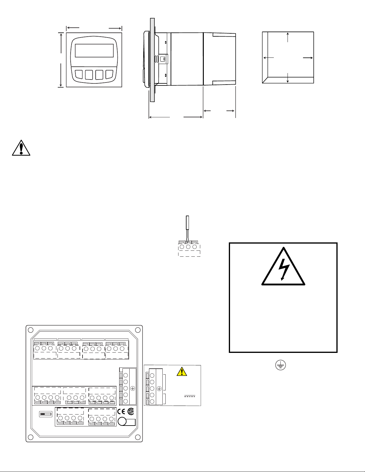
+GF+ SIGNET 8860 Dual Channel Conductivit /Resistivit Controller
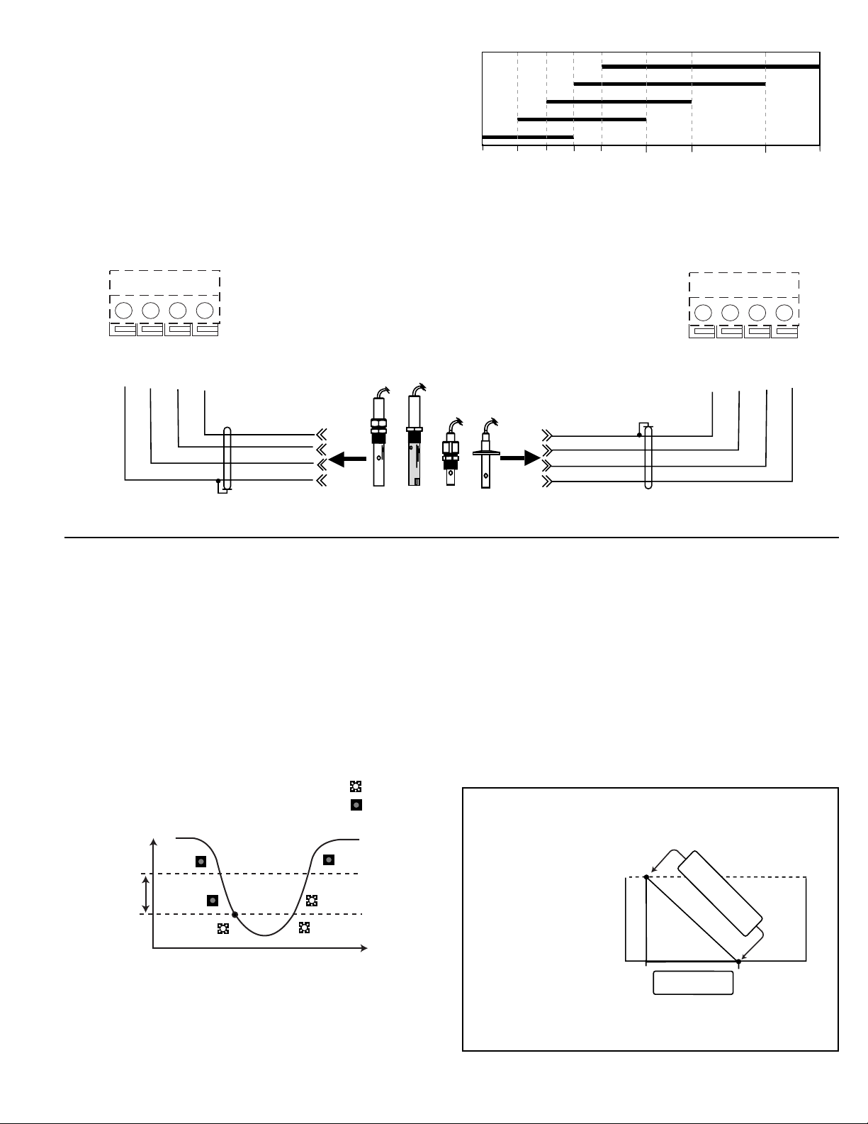
USP Limits
USP (United States Pharmacopoeia) has defined a set of conduc-
tivit values (limits) to be used for pharmaceutical water monitor-
ing. This standard requires non-temperature compensated
conductivit measurement be used to warn if the conductance
approaches the USP limit. The limits var according the tempera-
ture of the sample.
The 8860 has the USP limits stored in memor . It will automati-
call determine the proper USP limit based on the measured
temperature.
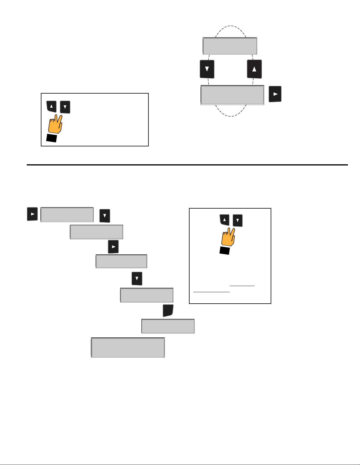
Using the USP function
In the 8860, USP setpoints are defined as a percentage below the
USP limit, so a USP alarm is alwa s a HIGH alarm.. The 8860
can be set to warn ou if the conductivit approaches within a set
percentage of the USP limit.
The following settings and conditions are required for a USP
relay function:
1. In the CALIBRATE menu:
• RELAY MODE must be set to USP.
• RELAY SOURCE must be Chan 1 or Chan 2 Cond.
• SOURCE UNITS must be set to µS.
2. In the OPTIONS menu:
• The TC Mode of the USP channel must be set to None.
(Service tip: If a relay is constantly on, check these settings.)
Example:
• The USP setpoint is 40%.
• The water temperature is 19 ºC, so the USP limit is 1.0 µS.
• The rela will be activated when the conductivit value reaches
0.6 µS, or 40% below the 1.0 USP limit.
• If the water temperature drifts to more than 20ºC, the 8860 will
automaticall adjust the USP limit to 1.1.
• The rela will now be activated when the conductivit value
reaches 40% below 1.1 µS, or 0.66 µS.
Temp range USP limit (µS):
0 to < 5 ºC 0. 6
5 to < 10 ºC 0. 8
10 to < 15 ºC 0.9
15 to < 20 ºC 1
20 to < 25 ºC 1.1
25 to < 30 ºC 1.3
30 to < 35 ºC 1.4
35 to < 40 ºC 1.5
40 to < 45 ºC 1.7
50 to < 55 ºC 1.8
55 to < 60 ºC 2.1
60 to < 65 ºC 2.2
65 to < 70 ºC 2.4
70 to < 75 ºC 2.5
75 to < 80 ºC 2.7
80 to < 85 ºC 2.7
85 to < 90 ºC 2.7
90 to < 95 ºC 2.7
95 to < 100 ºC 2.9
100 to < 105 ºC 3.1
Read "From zero to less than 5ºC."
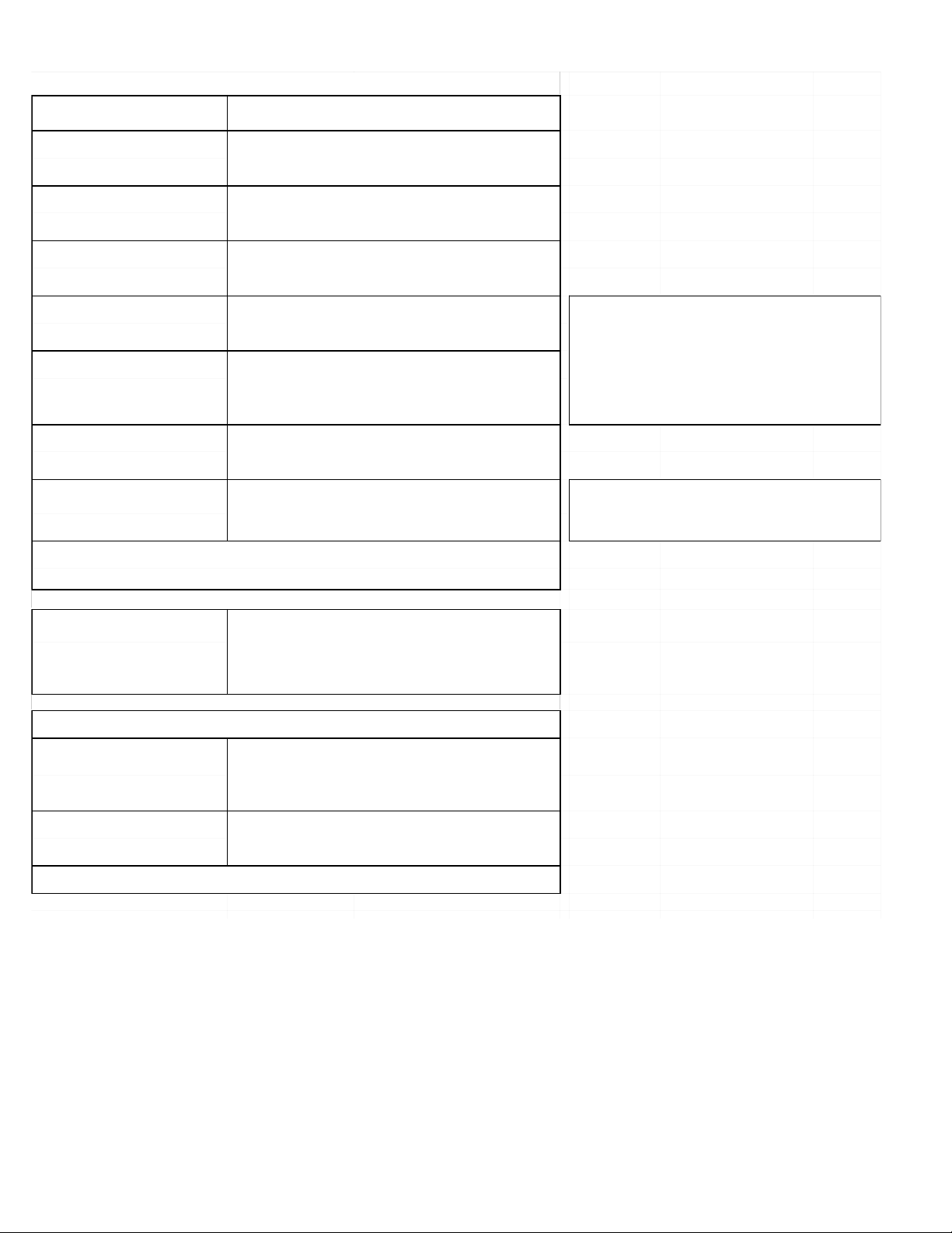
Relay 1 Mode:
LOW >
Relay 1 Source:
Chan 1 Cond >
Relay 1 Setpoint:
100.000 µS >
Relay 1 Hysteresis:
0.5 µS >
Relay 1 Delay:
00.0 seconds >
Relay 1 Rng: µS
100.000 1000.00
Relay 1 PlsRate:
120 pulses/min >
Repeat Settings for Relays 2, 3 and 4
Last Cal
06-30-00 >
The maximum PULSE rate is 400 pulses per minute.
Set a dela time up to 6400 seconds maximum. When
the source value reaches the SETPOINT, the RELAY will
not be activated until this time has elapsed.
If ou see "- - - -" in this setting, review the SOURCE and make sure it is consistent with
the setpoint value.
When the rela Mode is USP (defined as a HIGH alarm):
• The setpoint value is a percentage below the USP limit. •
H steresis is displa ed in µS.
NOTE: If the SOURCE value returns to within the SETPOINT value before this time has
elapsed, the RELAY will not be activated.
Rela will be deactivated at setpoint ± H steresis
(depending on High or Low selection).
If Rela mode is USP, then the SOURCE must be Cond 1 or Cond 2 and Temp Comp
(see OPTIONS menu) must be set to None
Select the INPUT SIGNAL (or FUNCTION) monitored b
this rela output: Cond 1, Cond 2, Temp 1, Temp 2,
Function
Select the desired mode of operation for this rela output:
OFF, LOW, HIGH, USP or PULSE.
Set the value where ou want this rela output to be
activated. The maximum value acceptable is 999999.
Use this "notepad" to record important dates, such as
annual recertification or scheduled maintenance.
Select the Mode and Setpoints for 4 output relays
If this output is set for PULSE mode, set the range for the
pulses to increase, from 0 to MAX RATE (see below.)
Set the maximum pulse rate for this output. The rela will
pulse at this rate when the SOURCE value is equal to the
maximum PULSE RANGE.