GF Signet 9050CR User manual

+GF+SIGNET 9050CR
Conductivity/Resistivity Controller
GEORGE FISCHER +GF+
Instruction Manual

CAUTION: Remove AC power to unit prior to
wiring input and output connections.
Important Safety Information!
CAUTION: Remove AC power before opening
unit. Electrical shock hazard exists

Chapter Page
1 Introduction 1
1.1 General Description 1
1.2 Front Panel Description 2
1.3 Rear Panel Description 3
2 Sensor Selection and Installation 4
2.1 Sensor Selection 4
2.2 In-Line Sensor Installations 6
2.3 Submersible Sensor Installations 8
3 Installation and Wiring 9
3.1 Mounting Instructions 9
3.2 Power Connections 10
3.3 Input Connections 11
3.4 Output Relay Connections 12
3.5 Verifying Analog Outputs 13
3.6 Analog Output Connections 14
4 System Configuration 15
4.1 Introduction 15
4.2 CAL Menu Functions 16
4.3 RELAY Menu Functions 18
4.4 OUTPUT Menu Functions 19
4.5
Quick-Reference Keypad Sequence
20
4.6 CAL Menu 22
4.7 Wet Calibration Procedure 24
4.8 Relay Operation 25
4.9 RELAY Menu 27
4.10 OUTPUT Menu 29
4.11 View Only Menus 30
5 Technical Support 32
5.1 Accessing Internal Options 32
5.2 AC Power Configurations 33
5.3 Security Code Function 33
5.4 Installing Input/Output Options 34
5.5 Output Card Configurations 34
5.6 Options and Accessories 35
Table of
Contents

5.7 Parts Per Million Conversion Factor 37
5.8 Temperature Coefficient 38
5.9 Troubleshooting 40
Specifications 43
Warranty Information 45

Unpacking and Inspection
Your controller package includes the following
items:
•+GF+SIGNET 9050CR Conductivity/
Resistivity Controller
• Two stainless steel mounting brackets
• Mounting Instructions w/self-adhesive template
• Panel gasket
• Instruction manual w/warranty card
Please fill out and return warranty card as soon as
possible.
Warranty Record
For your protection, record your unit's purchase
date and serial number for future reference. The
serial number decal is located on the instrument's
rear panel.
Model: +GF+SIGNET 9050CR Conductivity/
Resistivity Controller
Purchase Date: _______________________
Serial Number: ________________________
Purchased From: _______________________
Purchase Order Number: _______________


Chapter 1
Introduction
1.1 General Description
The +GF+SIGNET 9050CR Conductivity/
Resistivity Controller is specifically designed to
monitor and control conductivity levels of aqueous
solutions. The controller's compact 1/4 DIN
enclosure (front) is NEMA 4X/IP65 rated and
ideal for installations into instrumentation panels
with limited space.
Optional "plug-in" output cards allow you to
customize your controller to satisfy your application
demands. The controller's unique "slide-out"
chassis design makes option installation fast and
simple. Smart self-configuring microprocessor
based circuitry automatically inventories installed
options during power-up, allowing you to upgrade
your system in seconds without the need for
additional equipment.
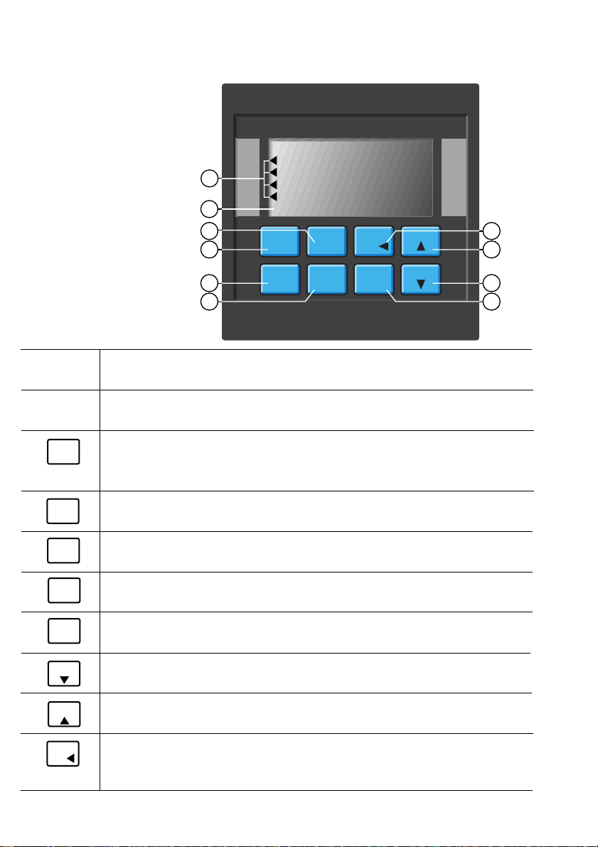
The unit's front panel features a highly visible
4.5 and 8-digit liquid crystal display with
adjustable contrast. Measured conductivity/
resistivity and relay status is accessed at a glance.
Channel selection and solution temperature is
accessed with a touch of a button. During
calibration the user is prompted with clear
step-by-step instructions on the front panel display.
The 9050CR is designed for use with
+GF+SIGNET 3-28XX-1 series sensors, covering
a wide range of conductivity/resistivity
measurement. Each sensor is equipped with a
PT1000 temperature compensation device for
accurate temperature sensing (sec. 2.1).
1
The technical data given in
this publication is for general
information purposes only. It
implies no warranty of any
kind.

COND
RES
1.2 Front Panel Description
• Accesses one of three calibration menus: CAL, RELAY, OUTPUT
• Selects a menu item for modification
• Restores a menu item to previous value during modification
1. Relay An-
nunciators:
3.
5.
6.
7.
• Indicate activation status of control relays 1-4 (optional)
• Shows conductivity, resistivity, temperature °C, relay activation status, and
user messages during setup and operation
• Stores calibration and setup values into memory after modification
• Displays available output options during operation
4.
• Displays temperature in °C for each channel during operation
• Decreases the value of a selected digit in CAL, RELAY, or OUTPUT menus
8.
9. • Displays percent rejection between channels
• Increases the value of a selected digit in CAL, RELAY, or OUTPUT menus
• Used in conjunction with MOD key to access the RELAY calibration menu
• Accesses the RELAY "view-only" menu
• Used in conjunction with MOD key to access the OUTPUT calibration menu
• Accesses the OUTPUT "view-only" menu
• Displays conductvity/resistivity for each channel during operation
• Selects a digit for modification while in CAL, RELAY, or OUTPUT menus
• Returns the unit to operation mode from menus
10.
2. LCD
Display:
• Used in conjunction with MOD key to access the CAL calibration menu
• Accesses the CAL "view-only" menu
FunctionItem
MOD
ENTER
CAL
RELAY
OUTPUT
TEMP
% REJ
2
RLY 1
ENTER MOD
CAL RELAY OUTPUT TEMP
RLY 2
RLY 3
RLY 4
9050CR Controller
COND
RES % REJ
+GF+SIGNET
7
8
9
103
4
5
6
2
1

3
1.3 Rear Panel Description
• 90 to 132 VAC or 180 to 264 VAC system power
connection 1. AC IN
• 17 to 30 VDC system power connection 2. DC IN
• Analog output #1 from option socket #1 (optional) 5. ANL1
• Sensor input connections 6. CH1/CH2
• Serial outputs (future availability) 7. SERIAL
• Analog output #2 from option socket #2 (optional) 8. ANL2
• Relay #1 (COM, NO, NC) contact set for external device
control (optional) 3. RLY1
• Relay #2 (COM, NO, NC) contact set for external device
control (optional) 4. RLY2
Note:
Rear terminals
accept 18 to 22 AWG
wire
• Relay #4 (COM, NO) contact set for external device
control (optional) 9. RLY4
• Relay #3 (COM, NO) contact set for external device
control (optional) 10. RLY3
Item
Function
15 16 17 18 19 20 21 22 23 24 25 26 27 28
L
1
N
AC IN
+ GND NO C NC
RLY1DC IN NO C NC
RLY2
R+ R-
ANL1
1 2 3 4 5 6 7 8 9 10 11 12 13 14
C NO Tx GND Rx
CH2
S2 T2 S1 T1 SGCNOR+ R-
RLY3 RLY4 SERIALANL2 CH1
10 9 8 7 6
12 3 4 5

Chapter 2
Sensor Selection
and Installation
2.1 Sensor Selection
The 9050CR controller is compatable with +GF+
SIGNET 3-28XX-1 series sensors. +GF+Signet
offers five sensor versions satisfying a wide range
of measurement, listed below.
For optimum sensor performance and life, the
following requirements MUST be met:
• Verify your system's conductivity/resistivity
range.
• Verify the maximum pressure/temperature
specification for the sensor under consideration
is within your process range.
• Verify wetted sensor parts are chemically
compatible with process fluids (e.g. Compass
Corrosion Guide or equivalent).
Choose the +GF+Signet sensor best suited for
your application from the following:
4
Dimensions:
• 3-2819-1 Sensor
• 3-2820-1 Sensor
• 3-2821-1 Sensor
Order NPT Fitting
Number Cell Range Fitting Material
3-2819-1 0.01 0.055 - 100 µS 3/4 in. PP
(10 kΩ- 18 MΩ)
3-2820-1 0.1 1 - 1000 µS 3/4 in. PP
3-2821-1 1.0 10 - 10,000 µS 3/4 in. PP
Specifications
Temperature Compensation: PT1000
Wetted materials:
O-rings: EPR
Insulator: Teflon®
Electrodes: 316 stainless steel
Standard fitting: Polypropylene
Max. pressure: 100 psi/6.9 bar
Max. temperature: 212 °F/100 °C
Optional fitting: 316 SS (1/2 in. NPT)
#3-2820.392
Max. pressure: 200 psi/13.8 bar
Max. temperature: 248 °F/120 °C
152 mm
(6.0 in.)
107 mm
(4.2 in.)
4.6 m (15 ft.)
cable (standard)
Reversible
fitting assy
for submersion
mounting
3/4 in. NPT
(standard)
12.7 mm
(0.5 in.) 3-2821-1
sensor tip
3-2820-1
sensor tip

5
Order NPT Fitting
Number Cell Range Fitting Material
3-2822-1 10.0 100 - 100,000 µS 3/4 in. 316 SS
Specifications
Temperature Compensation: PT1000
Wetted materials:
O-rings: EPR
Insulator: CPVC
Electrodes: 316 stainless steel
Standard fitting: 316 SS
Max. pressure: 100 psi /6.9 bar
Max. temperature: 203 °F /95 °C
Optional Submersion
Adapter Fitting: 316 SS, #3-2820.390
Plastic pipe/tank installations: When two 3-2822-1
sensors connected to the same controller, a minimum of
10 ft/3 m is required between sensors, if placed in the
same solution.
Metal pipe/tank installations: A 3-2822-1 will not work
with a 3-2823-1 sensor in the same system. Use two
3-2823-1 in these applications.
Dimensions:
3-2822-1 Sensor
Resistivity measurements within the 10 MΩto
18 MΩ(0.055 µS to 0.1 µS) range must be
performed in solution temperatures from
20 °C to 100 °C.
5.8 in./
147 mm
3.4 in./
86 mm
15 ft./4.6m
cable (standard)
Standard 3/4 in.
NPT/316 SS fitting
Optional 316 SS
submersion adapter
fitting - 3/4 in. NPT
threads,
#3-2820.390
0.75 in. 19 mm

6
Order NPT Fitting
Number Cell Range Fitting Material
3-2823-1 20.0 200 - 400,000 µS 3/4 in. 316 SS
Specifications
Temperature Compensation: PT1000
Wetted materials:
O-rings: EPR
Insulator: Teflon
Electrodes: 316 stainless steel
Fitting: 316 stainless steel
Max. pressure: 100 psi/6.9 bar
Max. temperature: 302 °F/150 °C
2.2 In-line Sensor Installations
+GF+SIGNET 3-28XX-1 series sensors are easily
mounted using standard female pipe fittings
available at local hardware stores.
For optimum system performance, several mounting
techniques must be observed. In-line applications
require special considerations unlike most
submersible types. Factors such as air bubbles,
"dead zones", excessive flow rates, and sediment
build-up are problems associated with pipeline
installations.
Air bubbles around the sensor electrodes can
cause the sensor to read lower conductivity values
than actual. Pockets or "dead zones" may
produce inaccurate reading since they isolate the
sensor from the main process stream.
Dimensions
3-2823-1 Sensor
8.0 in./
203 mm
15 ft./4.6 m
cable (standard)
3/4 in. NPT
Reversible
fitting assy
for submersion
mounting
3.5 in./
89 mm
0.75 in. 19 mm

Oils or sediments in the system can coat or clog
the sensor electrodes, causing poor response or no
response at all.
Mount the sensor in a location where the flow rate
is moderate. Ideally, the sensor should be
mounted where flow is directed into the sensor
cavity (e.g. elbow, tee).
Refer to the following illustration for recommended
mounting techniques.
7
• Refer to your sensor instruction manual for
specific sensor assembly and mounting
instructions.
• For other installations, contact your local +GF+
Signet distributor for additional information.
• After the sensor is first installed and the pipe is
filled with fluid, gently tap the sensor fitting
several times to release any air bubbles trapped
within the sensor cavity.
In-line
3-2819-1
3-2820-1
3-2821-1
3-2822-1
3-2823-1
3-2821-1
Use caution to avoid air bubble or
sediment trapping inside the electrode
cavity.
Submersible
Air
bubbles
Air
bubbles
3-2819-1
3-2820-1
3-2821-1
3-2822-1
3-2823-1
A
B
tee fitting
A
B
OR

8
2.3 Submersible Sensor Installations
+GF+SIGNET 3-2819-1, 3-2820-1, and
3-2821-1 sensors are easily modified for submers-
ible installation. An extension pipe and female
pipe union are required (customer supplied).
• 3-2822-1 sensor: this sensor can be
submersed via the optional submersion adapter
fitting #3-2820.390.
• 3-2823-1 sensor: conversion for submersion
mounting is similar to the illustration above.
Simply reverse the sensor's metal swedgelock
fitting assembly and refer to step #6 above.
• Shake the sensor/pipe assembly after
submersion to remove any trapped air bubbles
inside the electrode cavity. Aerated tanks may
require baffles to seperate the sensor from
bubble streams. Avoid mounting locations
where bubbles are present.
12
6
customer
supplied
pipe
customer
supplied
female
pipe
union
15 ft/4.6 m
cable std.
100 ft/30 m
max., Belden
#9770
5
3
4
Sealant
Sealant

90 mm X
90 mm
9
Chapter 3
Installation
and Wiring
3.1 Mounting Instructions
The controller's 1/4 DIN enclosure is specifically
designed for panel mounting. Adjustable mount-
ing brackets allow mounting in panels up to 1 in./
25 mm thick. An adhesive template and instruc-
tions are included to insure proper installation.
For outdoor and/or stand alone installations the
splash-proof NEMA 4X/IP65 rear cover kit is
recommended (ordered separately,
#3-9000.395).
Panel Cutout Instructions
Recommended panel cutout 3.54 in./90 mm
square. Maximum panel cutout 3.62 in./92 mm
square, DO NOT exceed. Use adhesive backed
template (included).
Panel cutout
5.7 in./145 mm 6 in./152 mm
7.2 in./183 mm
Mounting Clamp (included, 2 ea.)
*Optional NEMA 4X/IP65 Rear Cover
3.8 in. sq.
96 mm 3.5 in.
88 mm
Mounting Panel
Max. panel thickness = 1 in./25 mm
Panel
Gasket
SIDE VIEW
6.5 in./165 mm

10
Instructions
1. Jumper selectable for 90 to 132 OR 180 to 264 VAC
operation. Confirm AC power configuration before
applying power (sec. 5.2).
2. DC power can be connected simultaneously as a
backup power source, see section below.
3. *A direct or low impedance AC ground (earth ground)
MUST be used for proper operation.
4. To reduce the possibility of noise interference, AC
power lines must be isolated from signal lines.
3.2 Power Connections
AC Power Connections
Caution: Never connect live
AC lines to the instrument.
Electrical shock hazard exists
DC power is recommended
when ground fault interrupt
devices (GFI's) are used.
Caution: Never connect live
DC lines to the instrument.
Electrical shock hazard exists Note: AC/DC power can be connected simultaneously,
using DC power as an backup power source.
*A direct or low impedance earth ground must be used for
optimum performance
DC Power Connections
L1N
AC IN
+ GND NO C NC
RLY1DC IN NO C NC
RLY2
R+ R-
ANL1
17 to 30 VDC @ 0.5 A
GND
15 16 17 18 19 20 21 22 23 24 25 26 27 28
*
15 16 17 18 19 20 21 22 23 24 25 26 27 28
L1N
AC IN
+ GND NO C NC
RLY1DC IN NO C NC
RLY2
R+ R-
ANL1
90 to 132 VAC
OR
180 to 264 VAC
AC Hot
AC Ground*
AC Neutral

11
3.3 Input Connections
The 9050CR is compatible with +GF+SIGNET
3-28XX-1 series sensors. Wiring connections are
identical for ALL sensor versions.
Extended Cable Runs: Each sensor includes
15 ft/4.6 m of cable. Cable runs can extend up
to 100 ft/30 m using three conductor shielded
cable (Belden 9770 or equivalent).
• Shielding must be exactly as shown below
• Shielding must be maintained through cable
splice with cable extensions.
Caution: Remove instrument
power prior to making any
input/output connection.
Failure to do so may result in
personal injury or damage to
the instrument.
Special Considerations:
To reduce the possibility of noise interference, separate sensor
input lines from AC power lines.
C NO Tx GND Rx
CH2
S2 T2 S1 T1 SGCNOR+ R-
RLY3 RLY4 SERIALANL2 CH1
RED
WHITE
CLEAR (SHLD)
BLACK
RED
WHITE
CLEAR (SHLD)
BLACK
CH 2
CH 1
1 2 3 4 5 6 7 8 9 10 11 12 13 14
Sensors:
3-2819-1
3-2820-1
3-2821-1
3-2822-1
3-2823-1

12
3.4 Output Relay Connections
Up to two optional relay cards can be installed for
external device control. Each card contains two
independent relays controlled by either channel.
One of three relay modes are selected for each
relay (sec. 4.8). Relay contacts are rated at 5 A
maximum.
The 9050CR will accept one of each of the
following cards:
• 2-Relay Card: Provides two single pole double
throw relays (sec. 5.4).
• Dual Proportional Relay Card: Provides two
single pole single throw relays (sec. 5.4).
The 2-Relay Card provides both normally open
(NO) and normally closed (NC) contacts which
may be used simultaneously. Example: Device A
IS powered when relay 1 is off. Power is discon-
tinued when relay 1's alarm setpoint is reached.
Device B IS NOT powered when relay 1 is off.
Power is applied when relay 1's alarm setpoint is
reached, see illustration below:
Special Considerations:
Relay contacts are rated as
5 A @ 250 VAC OR
5 A @ 30 VDC max.
An external heavy-duty relay
must be used for devices with
surge currents or operating
currents that exceed 5 A.
To reduce the possibility of
noise interference, separate
AC relay lines from input/
output lines.
L1
AC IN
+ GND NO C NC
RLY1DC IN NO C NC
RLY2
R+ R-
ANL1
External
AC/DC
Power
Source
15 16 17 18 19 20 21 22 23 24 25 26 27 28
N
AC+
AC+
ACN
ACN
AC+
B
pump
solenoid
valve
A

13
The Dual Proportional Relay Card provides a
normally open (NO) contact for external device
control. The main distinction from the 2-Relay card
is the lack of the normally closed (NC) contact.
Example: Device A IS NOT powered when relay
3 is off. Power is applied when relay 3's alarm
setpoint is reached. Relay 4 operation is identical
to Relay 3, see illustration below:
3.5 Verifying Analog Outputs
Installed output options can be configured to either
of the unit's rear analog output terminals: ANL 1
or ANL 2. Configuration is determined by which
sockets the options are installed. Options installed
in socket #1 are configured to the rear ANL 1 ter-
minals, options installed in socket #2 are config-
ured to the rear ANL 2 terminals (sec. 5.4).
Prior to connection, determine which options are
configured to terminals ANL 1 and ANL 2 as
follows:
1 2 3 4 5 6 7 8 9 10 11 12 13 14
C NO Tx GND Rx
CH2
S2 T2 S1 T1 SGCNOR+ R-
RLY3 RLY4 SERIALANL2 CH1
External
AC/DC
Power
Source
-
+
-
-
+
+-
+Device B
Device A
External
AC/DC
Power
Source
Special Considerations:
Relay contacts are rated as
5 A @ 250 VAC OR
5 A @ 30 VDC maximum.
To reduce the possibility of
noise interference, separate
AC relay lines from input/
output lines.

14
1. Apply power to unit. Press: ENTER to view
available output options on the front panel display
(unit displays "No Card" for unavailable options).
2. Record option configurations for ANL 1 and
ANL 2 in the spaces provided (left). This informa-
tion is necessary when wiring analog outputs.
3.6 Analog Output Connections
0 to 20/4 to 20 mA isolated or non-isolated
outputs as well as 0 to 5/0 to 10 VDC isolated or
non-isolated outputs are available (sec. 5.5).
Special Considerations:
The maximum loop impedance for the 4 to 20 mA/0 to 20
mA output is 425
Ω
. The minimum load impedance for the
0 to 5/0 to 10 V output is 1 k
Ω
(1000
Ω
). To reduce the
possibility of noise interference, separate output lines from AC
power/relay lines.
Option Record:
ANL 1=
_____________________
ANL 2=
_____________________
1 2 3 4 5 6 7 8 9 10 11 12 13 14
15 16 17 18 19 20 21 22 23 24 25 26 27 28
L1N
AC IN
+ GND NO C NC
RLY1DC IN NO C NC
RLY2
R+ R-
ANL1
C NO Tx GND Rx
CH2
S2 T2 S1 T1 SGCNOR+ R-
RLY3 RLY4 SERIALANL2 CH1
Analog
Ouput #2
Analog
Output #1
-
+
+
-
*
The 4 to 20 mA option is
jumper configurable for
0 to 20 mA operation
(sec. 5.5).
Table of contents
Other GF Signet Controllers manuals