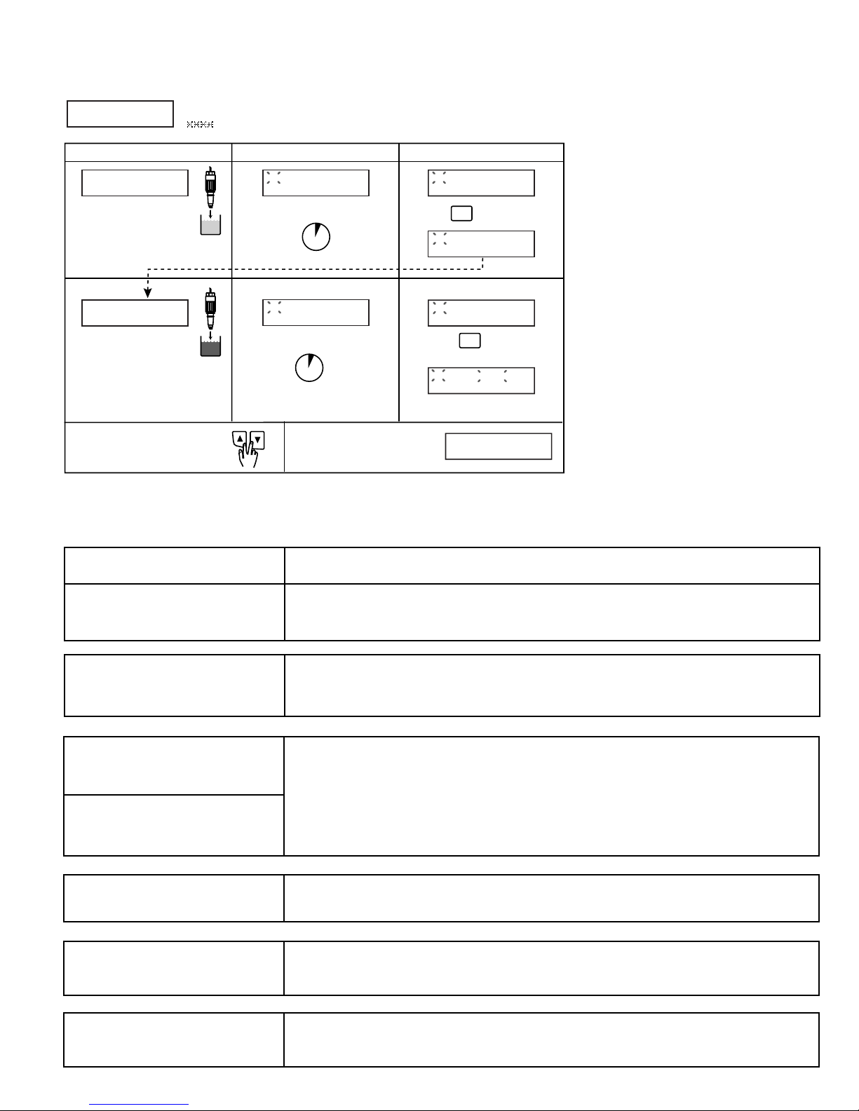
GF Signet 8750-2 User manual

pH/ORP
10.20 pH
25.0°C
Relay 1 Relay 2
ENTER
‡ SIGNET
8750-2 pH/ORP Transmitter
ENGLISH
2. Specifications
General
Compatible electrodes: +GF+ SIGNET Twist-Lock 3-2720 pH/ORP
Preamplifier/3-271X Electrodes
Accuracy: ±0.03 pH, ±2 mV's ORP
Enclosure:
•Rating: NEMA 4X/IP65 front
•Case: PBT
•Panel case gasket: Neoprene
• Window: Polyurethane coated polycarbonate
•Keypad: Sealed 4-key silicone rubber
•Weight: Approx. 325g (12 oz.)
Display:
• Alphanumeric 2 x 16 LCD
•Contrast: User selected, 5 levels
•Update rate: 1 second
Electrical
Power: 12 to 24 VDC ±10%, regulated, 220 mA max.
Sensor input range:
•pH: 0.00 to 14.00 pH
•Temp. (pH only) 3K Balco, -25 to 120°C (-13 to 248°F)
•ORP: -1000 to +2000 mV, isolated
(10KΩI.D. resistance T+, T-)
Current output:
•4to 20 mA, isolated, fully adjustable and reversible
•Max loop impedance: 50 Ωmax. @ 12 V
325 Ωmax. @ 18 V
600 Ωmax. @ 24 V
•Update rate: 0.5 seconds
•Accuracy: ±0.03 mA @ 25°C, 24 V
Relay outputs (2 sets mechanical SPDT contacts):
•Maximum voltage rating: 5 A @ 30 VDC, or 5 A @ 250 VAC
resistive load
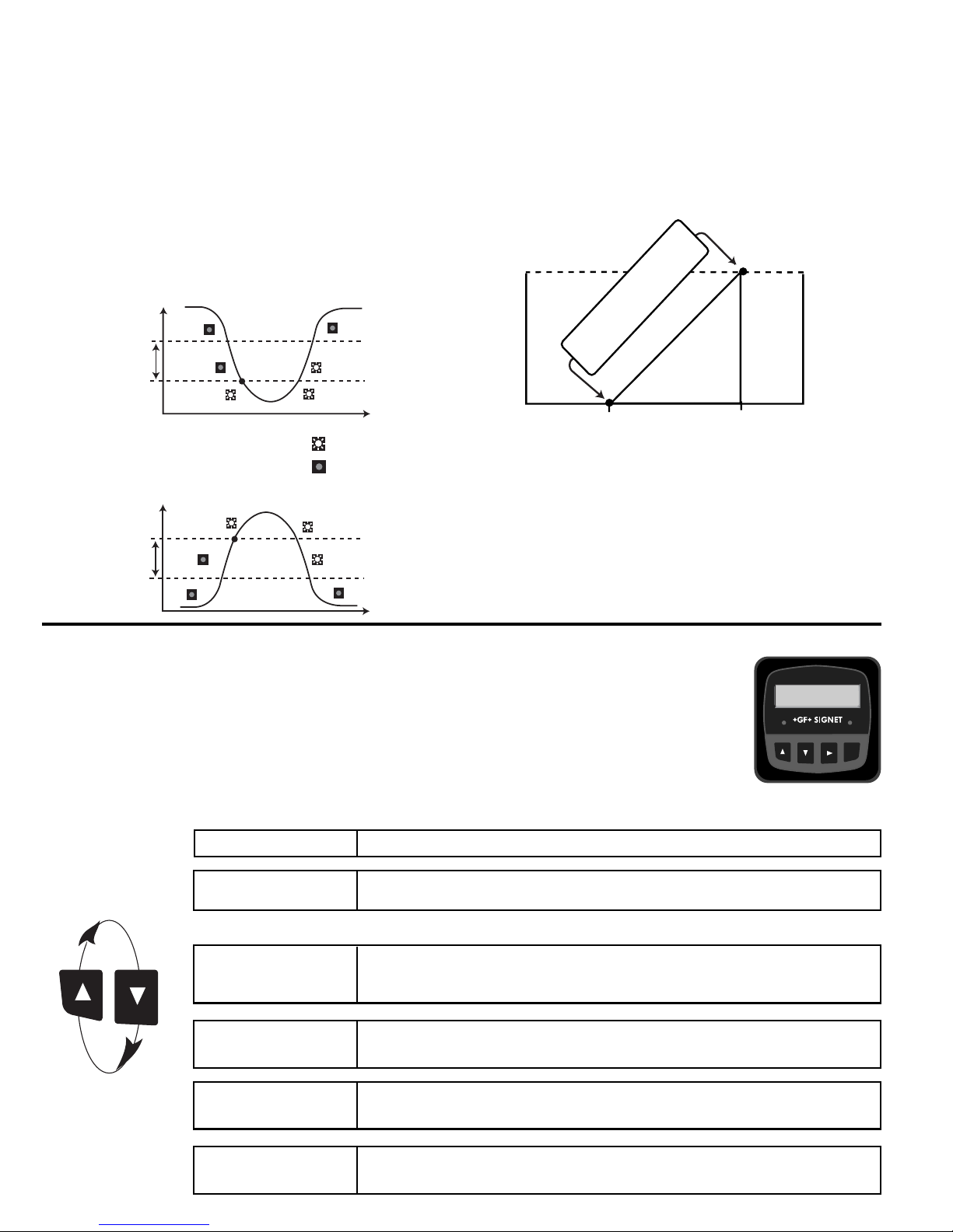
•Hi or Lo programmable with adjustable hysteresis
•Pulse programmable (maximum 400 pulses/minute)
Environmental
• Operating temperature: -10 to 70°C (14 to 158°F)
•Storage temperature: -15 to 80°C (5 to 176°F)
•Relative humidity: 0 to 95%, non-condensing
•Maximum altitude: 2000 m (6562 ft)
•Insulation category: II
•Pollution degree: 2
Standards and Approvals
•CSA, CE, UL listed
•Immunity: EN50082-2
•Emissions: EN55011 Class B
•Manufactured under ISO 9001 and ISO 14001
3-8750.090-2
D-4/03 English
CAUTION!
• Remove power to unit before wiring input and
output connections.
•Follow instructions carefully to avoid personal injury.
1. Installation
ProcessPro transmitters are available in two styles: panel mount and field mount. The panel mount is supplied with the necessary
hardware to install the transmitter. This manual includes complete panel mounting instructions.
Field mounting requires a separate mounting kit. The 3-8050 Universal kit enables the transmitter to be installed virtually
anywhere. Detailed instructions for field installation options are included with the 3-8050 Universal kit.
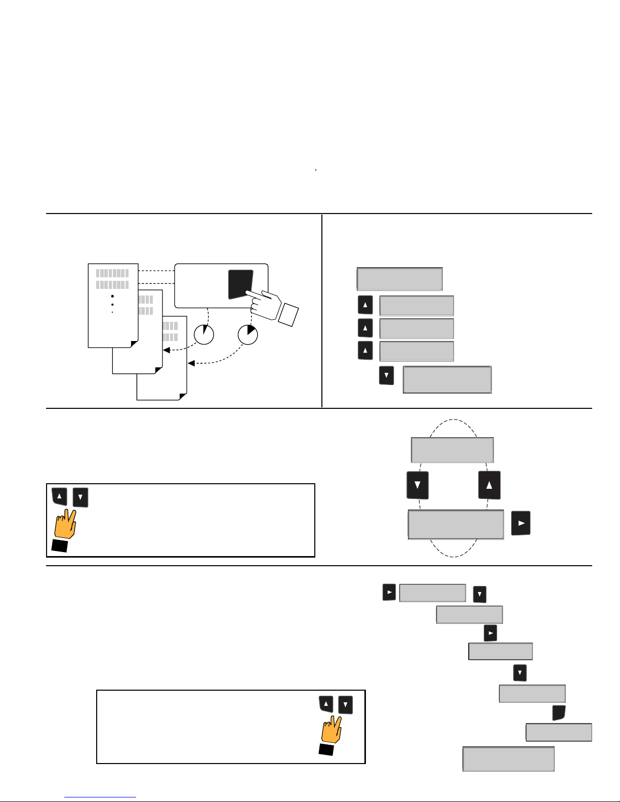
1.1 Panel Installation
1. The panel mount transmitter is designed for installation using a 1/4 DIN Punch. For manual panel cutout, an adhesive
template is provided as an installation guide. Recommended clearance on all sides between instruments is 1 inch.
2. Place gasket on instrument, and install in panel.
3. Slide mounting bracket over back of instrument until quick-clips snap into latches on side of instrument.
4. To remove, secure instrument temporarily with tape from front or grip from rear of instrument. DO NOT RELEASE.
Press quick-clips outward and remove.
Contents
1. Installation
2. Specifications
3. Electrical Connections
4. Menu Functions
106 mm (4.2 in.)
42 mm
(1.7 in.)
64 mm
(2.5 in.)
SIDE VIEW
92 mm
(3.6 in.)
97 mm
(3.8 in.)
56 mm
(2.2 in.)
41 mm
(1.6 in.)
Optional
Rear
Cover
Field Mount Panel Mount
FRONT VIEW
96 mm
(3.8 in.)
96 mm
(3.8 in.)
quick-clips
gasket panel
terminals mounting
bracket
latch
Output-
Output+
SystemPwr
Loop-
SystemPwr
Loop+
2
14
3
SensrGnd
(SHIELD)
SensrIN
(RED)
SensrV+
(BLACK)
7
6
5
SIDE VIEW
Field Mount &
Panel Mount Panel Mount
Installation Detail
82 mm
(3.23 in.)
8050

page 2 of 12 8750-2 pH/ORP Transmitter‡ SIGNET
System Pwr
Loop -
System Pwr
Loop +
AUX
Power -
AUX
Power +
4
3
2
1
Earth
GND
Sensr Gnd
(SHIELD)
V-
(BLACK)
V+
(RED)
14
13
12
11
Temp -
(WHITE)
Temp +
(GREEN)
Iso. GND
(BLUE)
mV Input
(BROWN)
18
17
16
15
Relay 2
(NO)
Relay 2
(COM)
Relay 2
(NC)
Relay 1
(NO)
Relay 1
(COM)
Relay 1
(NC)
10
9
8
7
6
5
3. Electrical Connections
Caution: Failure to fully open terminal jaws before removing wire may permanently damage instrument.
Wiring Procedure
1. Remove 0.5 - 0.625 in. (13-16 mm) of insulation from wire end.
2. Press the orange terminal lever downward with a small screwdriver to open terminal jaws.
3. Insert exposed (non-insulated) wire end in terminal hole until it bottoms out.
4. Release orange terminal lever to secure wire in place. Gently pull on each wire to ensure a good connection.
Wiring Removal Procedure
1. Press the orange terminal lever downward with a small screwdriver to open terminal jaws.
2. When fully open, remove wire from terminal.
Wiring Tips:
•Do not route sensor cable in conduit containing AC power wiring. Electrical noise may interfere with sensor signal.
• Routing sensor cable in grounded metal conduit will help prevent electrical noise and mechanical damage.
•Seal cable entry points to prevent moisture damage.
•Only one wire should be inserted into a terminal. Splice double wires outside the terminal.
2
1
Terminals 15-18: Sensor connections
15-16 are mV (pH or ORP) input from the electrode.
17-18 are temperature input from the pH electrode or
10KΩidentifying resistor from the ORP electrode.
Terminals 11-14: Preamplifier power and grounds
11-12 are DC voltages from the 8750 to power the
preamplifier.
13-14 are ground terminals for the sensor and for
earth ground
Terminals 1 and 2: AUXILIARY power
Provides power for relay operation.
Terminals 5-10: Relay Outputs
Two sets mechanical SPDT contacts,
programmable (see CALIBRATE menu) as:
• High or Low with adjustable hysteresis
• proportional pulse based on pH or ORP
• May be disabled (Off) if not used.
Terminals 3 and 4: Loop Power
12-24 VDC ±10% system power
and current loop output.
Max. loop impedance:
50 Ωmax. @ 12 V
325 Ωmax. @ 18 V
600 Ωmax. @ 24 V

page 3 of 128750-2 pH/ORP Transmitter ‡ SIGNET
3.2 System Power/Loop Connections
Stand-alone application, no current loop used
Transmitter
Terminals
Power
Supply
12–24 VDC
Connection to a PLC with built-in power supply
Internal
PLC
Connection
Connection to a PLC/Recorder, separate supply
Example: Two transmitters connected to PLC/Recorder with separate power supply
–
+
PLC or Recorder
Loop Input
4-20 mA
System Pwr Loop –
System Pwr Loop +
AUX Power –
AUX Power +
4
3
2
1
4
3
2
1
Transmitter
Terminals
Power
Supply
12–24 VDC
–
+
System Pwr Loop –
System Pwr Loop +
AUX Power –
AUX Power +
4
3
2
1
+
–
AUX power required for all 8850 systems
PLC or Recorder
Channel 1
4-20 mA in
Channel 2
4-20 mA in
+
–
–
+
Transmitter 1
Terminals
System Pwr Loop –
System Pwr Loop +
AUX Power –
AUX Power +
System Pwr Loop –
System Pwr Loop +
AUX Power –
AUX Power +
4
3
2
1
4
3
2
1
Transmitter 2
Terminals
4
3
2
1
PLC Terminals
Loop Input
4-20 mA
Transmitter
Terminals
System Pwr Loop –
System Pwr Loop +
AUX Power –
AUX Power +
4
3
2
1
+
–
Power
Supply
12–24 VDC
–
+
Power
Supply
12–24 VDC
–
+
4
3
2
1
4
3
2
1
18
17
16
15
14
13
12
11
White (Temp)
Green (Temp)
Blue (ISO GND)
Brown (mV input)
Silver (Shield)
Black (V-)
Red (V+)
Preamp:
+GF+ SIGNET 2720
pH Electrodes
+GF+ SIGNET 2714, 2714-HF
+GF+ SIGNET 2716
ORP Electrodes:
+GF+ SIGNET 2715
+GF+ SIGNET 2717
* (connection of terminal 14 to Earth GND
may reduce electrical interference)
Terminals
*
3.1 Sensor Input Connections
Transmitter
≤ 400 ft. (122 m)
pH/ORP

page 4 of 12 8750-2 pH/ORP Transmitter‡ SIGNET
VIEW menu
•During normal operation, ProcessPro displays the VIEW menu.
• When using the CALIBRATE or OPTIONS menus, ProcessPro will return to the VIEW menu if no activity
occurs for 10 minutes.
•To select the item you want displayed, press the UP or DOWN arrow keys. The items will scroll in a
continuous loop. Changing the display selection does not interrupt system operations.
•No key code is necessary to change display selection.
•Output settings cannot be edited from the VIEW menu.
Hysteresis
Time
Low Setpoint
Process
Relay energized
Relay relaxed
Hysteresis
Time
High Setpoint
Process
pH/ORP
10.20 pH
25.0°C
Relay 1 Relay 2
ENTER
•Proportional Pulsing
The relay output will generate a 100 mS pulse at the rate defined
by settings in the CALIBRATE menu (see page 6)
In the example below:
•The output will be 0 pulses/min. at pH values less than 5.0.
•The output will be 50 pulses/min. at 7.5 pH.
•The output will be 100 pulses/min. at pH values above 10 pH.
3.3 Open Collector Output
The relay outputs can be programmed to respond when the pH/
ORP value moves above or below a setpoint, or it can be used to
generate a pulse that is proportional to the pH/ORP value.
The relays can be disabled if not in use.
•Low
Relay triggers when the pH/ORP is less than the setpoint.
The relay will relax when the pH/ORP moves above the setpoint
plus the hysteresis value.
•High
Relay triggers when the pH/ORPis greater than the setpoint.
The relay will relax when the pH/ORP drops below the setpoint
plus the hysteresis value.
10
5
Relay Output Rate:
0 to 100 Pulses/min.
endpoint
Pulse rate
0 pulses
100 pulses
Starting point
7.00 pH
12.6 ºCMonitor the Temperature input from the sensor.
This is the Permanent display.
All of the VIEW displays below are temporary. The permanent display will return after ten minutes.
Input:
307 mV
Loop Output:
14.16 mA
Last CAL:
06-30-00 >
EASY
CAL: >
Monitor the millivolt input from the electrode. Use this display to determine the
relative condition of your electrode during periodic calibration.
(7 pH buffer = 0 mV, ±50 mV)
Monitor the 4-20 mA Loop output.
Monitor date for scheduled maintenance or date of last calibration.
Easy Cal is the fastest and simplest periodic calibration method. Requires
4 pH, 7 pH and 10 pH. (Any two)
View Menu for pH
Display Description

page 5 of 128750-2 pH/ORP Transmitter ‡ SIGNET
Notes on Steps 5 and 6:
• All output functions remain active during editing.
• Only the flashing element can be edited.
• RIGHT ARROW key advances the flashing element in a continuous loop.
• Edited value is effective immediately after pressing ENTER key.
• If no key is pressed for 10 minutes unit will restore the last saved value and return to step 3.
• Step 6 (pressing ENTER key) always returns you to Step 3.
• Repeat steps 3-6 until all editing is completed.
Notes on Step 2:
If no key is pressed for 5 minutes while display is showing "Enter
Key Code", the display will return to the VIEW menu.
Notes on Steps 3 and 4:
• Refer to pages 6 and 7 for complete listing of menu items and their use.
• From the Step 3 display, pressing the UP and DOWN keys simultaneously will
return the display to the VIEW menu.
• If no key is pressed for 10 minutes, display will also return to the VIEW menu.
ProcessPro Editing Procedure:
Step 1. Press and hold ENTER key:
• 2 seconds to select the CALIBRATE menu
• 5 seconds to select the OPTIONS menu.
Step 2. The Key Code is UP-UP-UP-DOWN keys in sequence.
• After entering the Key Code, the display will show the first item in the selected menu.
Step 3. Scroll menu with UP or DOWN arrow keys.
Step 4. Press RIGHT ARROW key to select menu item to be edited.
• The first display element will begin flashing.
Step 5. Press UP or DOWN keys to edit the flashing element.
• RIGHT ARROW key advances the flashing element.
Step 6. Press ENTER key to save the new setting and return to Step 3.
OPTIONS
CALIBRATE
VIEW
2s 5s
Press &
hold for
access:
ENTER
Step 5
Step 6
Notes on Step 1:
• The View Menu is normally displayed.
• The CALIBRATE and OPTIONS menus require a KEY CODE.
Step 4
First item in
CALIBRATE menu
Step 3
Step 3: Finished Editing?
Press the UP and DOWN keys simultaneously after
saving the last setting to return to normal operation.
Press the UP and DOWN keys simultaneously
while any element is flashing. This will recall the
last saved value of the item being edited and
return you to Step 3.
Step 5: Made an Error?
CALIBRATE: ----
Enter Key Code
CALIBRATE: *---
Enter Key Code
CALIBRATE: **--
Enter Key Code
CALIBRATE: ***-
Enter Key Code
Temperature >
Set:
10.0 pH>
Relay1 Setpnt:
Temperature >
Set:
Relay1 Setpnt:
1
0.00 pH
Relay1 Setpnt:
0
0.00 pH
ENTER
Relay1 Setpnt:
0
0
.00 pH
Relay1 Setpnt:
0
9
.00 pH
Relay1 Setpnt:
Saving
Relay1 Setpnt:
9.00 pH >

page 6 of 12 8750-2 pH/ORP Transmitter‡ SIGNET
Provides a maximum 25ºC offset to match temperature measurement to external reference.
Applies a linear offset to the pH measurement. The ideal value is the average pH of your
application. (A sample of your application at process temperature is recommended.)
Applies a slope to the pH measurement. The slope value and the standard value must be
at least 2 pH units apart. The ideal values are the minimum and maximum values of your
process.
Select the minimum and maximum values for the 4-20 mA Current loop output.
Select pH or Temperature as the source for this relay.
Select the mode of operation for this relay: High, Low or proportional Pulse.
The signal may be disabled if not in use.
In Low or High Mode, the relay will be activated when the pH reaches this value.
In Low or High mode, the relay will be deactivated at Setpoint ±Hysteresis, depending on
High or Low Setpoint selection. (See details on page 4.)
If Relay 1 is in PULSE mode, set the start and end point of the range and also set the
maximum pulse rate. (The maximum PULSE rate setting is 400 pulses per minute.)
The combined Relay1 Range and Relay1 Pulse rate settings shown here indicate:
"Start pulsing when the pH value is 4 and increase the pulse rate up to the maximum of
120 pulses per minute when the pH value reaches 8"
Use this “note pad” to record important dates, such as annual recertification or scheduled
maintenance.
Set:
Temperature >
Set:
Standard >
Set:
Slope >
Loop Range: pH
0.00 →→
→→
→14.00 >
Relay1 Source:
pH >
Relay1 Mode:
Off >
Relay1 Setpnt:
4.00 pH >
Relay1 Hys:
0.51 pH >
Relay1 Range:
4.00 →→
→→
→8.00 >
Relay1 PlsRate:
120 Pulses/min >
Last CAL:
06-30-01 >
Calibrate Menu for pH
Display
(Factory settings shown) Description

page 7 of 128750-2 pH/ORP Transmitter ‡ SIGNET
Adjust the LCD contrast for best viewing. A setting of 1 is lower contrast, 5 is higher.
Select lower contrast if the display is in warmer ambient surroundings.
OFF provides the most instantaneous output response to changes in input value.
LOW averaging = 4 seconds, HIGH averaging = 8 seconds of input signal.
Select temperature units: ºC or ºF.
Adjust the minimum and maximum current output. The display value represents the
precise current output.
Adjustment limits:
• 3.80 mA < 4.00 mA > 5.00 mA
• 19.00 mA < 20.00 mA > 21.00 ma
Use this setting to match the 8750 loop output to any external device.
Press UP or DOWN keys to manually order any output current value from 3.6 mA to
21.00 mA to test current loop output.
Press UP or DOWN keys to manually toggle the state of the relay output.
Contrast:
3>
Averaging:
Off >
Temp Display:
ºC>
Loop Adjust:
4.00 mA
Loop Adjust:
20.00 mA >
Test Loop:
>
Test Relay 1:
>
Test Relay 2:
>
Options Menu for pH
Display
(Factory settings shown) Description
EASY CAL Procedure - pH
•This procedure simplifies system calibration using standard 4.0, 7.0, 10.0 pH buffers only. If these pH buffers are not available,
calibrate the system via the CALIBRATE menu, using the STANDARD and SLOPE settings.
•Access the CALIBRATE menu and set sensor temperature before performing EASY CAL for new electrode installations.
•Access EASY CAL menu from the view menu.
Theoretical mV values
pH @ 25°CmV
2+296
3+237
4+177
5+118
6+59
7+0
8-59
9-118
10 -177
11 -237
12 -296
To Calibrate: Response:
To Accept:
Place electrode tip in
first pH buffer
pH 7.0 = 0 mV
pH 4.0 = 177
pH 10 = -177
Limit ± 50 mV
Allow for stabilization to accept
Place electrode tip
in second pH buffer.
Allow for stabilization
Press to accept
second buffer calibration.
ENTER
ENTER
* 7.00 pH
-005 mV
* 6.90 pH
-005 mV
* 3.93 pH
+179 mV
1
2
30 seconds*
30 seconds*
Press UP, UP, UP, DOWN buttons in sequence to enter menu,
XXXX will appear during code entry.
EASY CAL: ----
Enter Key Code
Place Sensor in
pH Buffer #1
Place Sensor in
pH Buffer #2
* 6.90 pH
-005 mV
* 3.93 pH
+179 mV
* 4.00 pH
+179 mV
_ _ _ _
To exit menus and return to
VIEW press UP and DOWN
button at the same time
Display returns to VIEW
Menu in 10 minutes or
when ENTER is pressed
Good Easy Cal
Press <ENTER>

page 8 of 12 8750-2 pH/ORP Transmitter‡ SIGNET
Applies a linear offset to the ORP measurement. If you are using a single-point calibration,
use this function. The ideal value is the average pH of your application. (A sample of your
application at process temperature is recommended.)
Applies a slope to the ORP measurement. This function should only be used in a two-point
calibration. The slope value and the standard value must be at least 2 pH units apart. The
ideal values are the minimum and maximum values of your application.
Select the minimum and maximum ORP values for the 4-20 mA Current loop output.
Maximum settings are -1000 mV to +2000 mV.
Select the mode of operation for this relay: High, Low or proportional Pulse.
The signal may also be disabled if not in use.
In Low or High Mode, the relay will be activated when the ORP reaches this value.
In Low or High mode, the relay will be deactivated at Setpoint ±Hysteresis, depending on
High or Low Setpoint selection. (See details on page 4.)
If Relay 1 is in PULSE mode, set the start and end point of the range and also set the
maximum pulse rate. (The maximum PULSE rate setting is 400 pulses per minute.)
The combined Relay1 Range and Relay1 Pulse rate settings shown here indicate:
"Start pulsing when the ORP value is -500 and increase the pulse rate up to the maximum
of 120 pulses per minute when the ORP value reaches +500"
Use this “note pad” to record important dates, such as annual recertification or scheduled
maintenance.
Calibrate Menu for ORP
Display
(Factory settings shown) Description
Set:
Standard >
Set:
Slope >
Loop Range: mV
-1000 > +1000 >
Relay1 Mode:
Off >
Relay1 Setpnt:
-500 mV >
Relay1 Hys:
10 mV >
Relay1 Range: mV
-500 →→
→→
→+500 >
Relay1 PlsRate:
120 pulses/min >
Last Cal:
06-30-01 >

page 9 of 128750-2 pH/ORP Transmitter ‡ SIGNET
Contrast:
3>
Averaging:
Off >
Loop Adjust:
4.00 mA >
Loop Adjust:
20.00 mA >
Test Loop:
>
Test Relay 1:
>
Test Relay 2:
>
Adjust the LCD contrast for best viewing. A setting of 1 is lower contrast, 5 is higher.
Select lower contrast if the display is in warmer ambient surroundings.
OFF provides the most instantaneous output response to changes in input value.
LOW averaging = 4 seconds, HIGH averaging produces more stable display and
output response.
Adjust the minimum and maximum current output. The display value represents the
precise current output.
Adjustment limits:
• 3.80 mA < 4.00 mA > 5.00 mA
• 19.00 mA < 20.00 mA > 21.00 ma
Use this setting to match the 8750 loop output to any external device.
Press UP or DOWN keys to manually order any output current value from 3.6 mA to
21.00 mA to test current loop output.
Press UP or DOWN keys to manually toggle the state of the relay.
Options Menu for ORP
Display
(Factory settings shown) Description
EASY CAL Procedure - ORP
•This procedure simplifies system calibration using standard 4.0 pH and 7.0 pH buffers saturated with Quinhydrone. To calibrate
using any other ORP buffer solutions, use the Standard and Slope functions in the CALIBRATE menu.
•Access EASY CAL menu from the view menu.
*For best results, gently stir the
submerged electrode for approximately 5
seconds during the stabilization period.
Large temperature differences from
process fluids to buffers may require
longer stabilization time.
Technical notes:
The difference between the actual mV and
value shown is a good indication of the
condition of the electrode.
Differences in excess of 50 mV may
indicate a need to service the electrode.
To Calibrate: Response:
To Accept:
Place electrode tip
in first pH buffer;
pH 7.0 ≈87 mV
pH 4.0 ≈264 mV
Allow for stabilization to accept
Place electrode tip
in second (different)
pH buffer.
pH 4.0 ≈264 mV
pH 7.0 ≈87 mV
Allow for stabilization
Press to accept
second buffer calibration.
ENTER
ENTER
* ORP: + 84 mV
Input: + 82 mV
1
2
30 seconds*
30 seconds*
Press UP, UP, UP, DOWN buttons in sequence to enter menu,
will appear during code entry.
EASY CAL: ----
Enter Key Code
Place Sensor in
ORP Buffer #1
Place Sensor in
ORP Buffer #2
* ORP: + 84 mV
Input: + 82 mV
* ORP: + 87 mV
Input: + 82 mV
* ORP: +262 mV
Input: +260 mV
* ORP: +262 mV
Input: +260 mV
* ORP: +264 mV
Input: +260 mV
To exit menus and return to
VIEW press UP and DOWN
button at the same time
Display returns to VIEW
Menu in 10 minutes or
when ENTER is pressed
Good Easy Cal
Press <ENTER>

page 10 of 12 8750-2 pH/ORP Transmitter‡ SIGNET
The mV value from the sensor when placed in a 7 pH buffer represents the sensor offset. Signet recommends servicing/replacing the
sensor when the offset exceeds 50 mV.
The 3-2759 pH/ORP system tester allows simple system troubleshooting.
1. Use pH 4, 7, 10 buffers.
2. Clean probe and retry EASY CAL.
3. Use Manual calibration for Standard and
Slope if mV offset exceeds 50 mV.
1. Place sensor in correct buffer solution.
2. Use fresh buffer.
1. Use pH values at least 2 pH units apart.
2. Clean pH sensor; replace if necessary.
3. Use fresh buffer.
1. Use pH values at least 2 pH units apart.
2. Clean pH sensor; replace if necessary
3. Use fresh buffer.
1. Check all wiring, contacts in preamplifier.
2. Verify sensor is securely installed.
3. Replace electrode pH sensor.
1. Recalibrate system.
2. Replace pH sensor.
3. Replace preamplifier.
1. Check all wiring, contacts in preamplifier.
2. Verify sensor is securely installed.
3. Replace pH sensor.
1. Required 4, 7 or 10 buffers not being
used.
2. Sensor is depleted too severely to use
EasyCal.
Sensor was not moved from buffer #1 to
buffer #2.
1. pH Standard value within 2 pH units of
Slope value.
2. pH Sensor efficiency is inadequate.
1. pH Slope value within 2 pH units of
Standard value.
2. pH Sensor efficiency is inadequate.
1. No temperature or mV signal from
sensor detected.
2. No connection between pH sensor and
preamplifier.
mV input is less than 0 pH or greater than
15 pH.
1. No temperature or mV signal from
sensor detected.
2. No connection between pH sensor
and preamplifier.
During EasyCal:
"Out of Range
Use Manual CAL"
During EasyCal:
"Same Buffer"
During CALIBRATE Std:
"Standard too close to Slope!"
During CALIBRATE Slope:
"Slope too close to Standard!"
During CALIBRATE:
"Out of Range
Check Sensor"
During normal operation:
Constant "15.00 pH"
or
constant "0.00 pH"
with good temp value
During normal operation:
"Check Sensor?"
Suggested Solutions
Troubleshooting - pH
Display Condition Possible causes

page 11 of 128750-2 pH/ORP Transmitter ‡ SIGNET
1. Use pH 4, 7 buffers saturated with
quinhydrone.
2. Clean probe and retry EASY CAL.
3. Use Manual calibration for Standard and
Slope if mV offset exceeds 50 mV.
1. Place sensor in correct buffer solution.
2. Use fresh buffer.
1. Use ORP values at least 120 mV apart.
2. Clean ORP sensor; replace if necessary.
3. Use fresh buffer.
1. Use ORP values at least 120 mV apart.
2. Clean ORP sensor; replace if necessary
3. Use fresh buffer.
1. Check all wiring, contacts in preamplifier.
2. Verify sensor is securely installed.
3. Replace ORP sensor.
1. Recalibrate system.
2. Replace pH sensor.
3. Replace preamplifier.
1. Check all wiring, contacts in preamplifier.
2. Verify sensor is securely installed.
3. Replace ORP sensor.
1. Required 4, 7 buffers with
quinhydrone not being used.
2. Sensor is depleted too severely to
use EasyCal.
Sensor was not moved from buffer #1 to
buffer #2.
1. ORP Standard value within 120 mV
of Slope value.
2. ORP Sensor efficiency is inadequate.
1. ORP Slope value within 120 mV of
Standard value.
2. ORP Sensor efficiency is inadequate.
1. No mV signal or sensor id from
sensor detected.
2. No connection between ORP sensor
and preamplifier.
mV input is less than -999 or greater
than +1999.
1. No temperature or mV signal from
sensor detected.
2. No connection between ORP sensor
and preamplifier.
During EasyCal:
"Out of Range
Use Manual CAL"
During EasyCal:
"Same Buffer"
During CALIBRATE Std:
"Standard too close to Slope!"
During CALIBRATE Slope:
"Slope too close to Standard!"
During CALIBRATE:
"Out of Range
Check Sensor"
During normal operation:
Constant "-1000"
or
constant ""+2000"
During normal operation:
"Check Sensor?"
Troubleshooting - ORP
Display Condition Possible causes Suggested Solutions

‡ SIGNET
Signet Scientific Company, 3401 Aerojet Avenue, El Monte, CA 91731-2882 U.S.A. • Tel. (626) 571-2770 • Fax (626) 573-2057
For Worldwide Sales and Service, visit our website: www.gfsignet.com • Or call (in the U.S.): (800) 854-4090
GEORGE FISCHER ‡ Piping Systems
3-8750.090-2/(D-4/03) English © Signet Scientific Company 2001 Printed in U.S.A. on recycled paper
Ordering Information
Mfr. Part No. Code Description
3-8750-1 159 000 053 pH/ORP transmitter Field mount
3-8750-1P 159 000 054 pH/ORP transmitter Panel mount
3-8750-2 159 000 055 pH/ORP transmitter Field mount with relays
3-8750-2P 159 000 056 pH/ORP transmitter Panel mount with relays
3-8750-3 159 000 057 pH/ORP transmitter Field mount with single input/dual output
3-8750-3P 159 000 058 pH/ORP transmitter Panel mount with single input/dual output
Accessories
Mfr. Part No. Code Description
3-2714 198 844 300 Twist-Lock Flat pH electrode
3-2714-HF 198 844 305 Twist-Lock Flat pH hydrofluoric acid resistant electrode (<2%)
3-2716 198 844 302 Twist-Lock Bulb pH electrode
3-2716-DI 198 844 306 Twist-Lock Bulb pH electrode for process liquids (< I00 µs)
3-2715 198 844 301 Twist-Lock Flat ORP Electrode
3-2717 198 844 303 Twist-Lock Bulb ORP Electrode
3-2720 198 864 602 Twist-Lock Preamplifier, 1/4in. NPT
3-2720-2 198 864 603 Twist-Lock Preamplifier, ISO 7/1-R 3/4
P31542 198 801 630 Red sensor cap for in-line installations
P31542-3 159 000 464 Blue sensor cap for in-line installations
3-2759 159 000 762 pH/ORP system tested (includes bypass adapter)
3-2759.393 159 000 765 2720 Adapter Cable
P31515-0P200 159 000 630 PVC Pipe Adapter
P31515-0C200 159 000 631 CPVC Pipe Adapter
P31515-0V200 159 000 459 PVDF Pipe Adapter
1220-0021 198 801 186 O-ring, FPM (standard)
1224-0021 198 820 006 O-ring, EPR
1228-0021 198 820 007 O-ring, Kalrez®
3-8050 159 000 184 Universal mounting kit
3-8050.395 159 000 186 Splashproof rear cover
3-8050.396 159 000 617 RC Filter kit (for relay use)
3-8052 159 000 188 3/4” Integral mounting kit
3-8052-1 159 000 755 3/4" NPT mount junction box
3-0000.596 159 000 641 Heavy duty wall mount bracket
3-0700.390 198 864 403 pH buffer kit
3-8050.392 159 000 640 Model 200 retrofit adapter
3-5000.598 198 840 225 Surface mount bracket
3-5000.399 198 840 224 5 x 5 inch adapter plate for +GF+ Signet retrofit
3-9000.392 159 000 368 Liquid-tight connector kit, 3 sets, 1/2 in. NPT
3-9000.392-1 159 000 839 Liquid-tight connector kit, 1 set, 1/2 in. NPT
3-9000.392-2 159 000 841 Liquid-tight connector kit, 1 set, PG 13.5
7300-7524 159 000 687 24 VDC Power Supply 7.5 W, 300mA
7300-1524 159 000 688 24 VDC Power Supply 15 W, 600mA
7300-3024 159 000 689 24 VDC Power Supply 30 W, 1.3 A
7300-5024 159 000 690 24 VDC Power Supply 50 W, 2.1 A
7300-1024 159 000 691 24 VDC Power Supply 100 W, 4.2 A
3-3719-11 159 000 804 pH/ORP Wet-Tap, 11/2in. NPT
3-3719-21 159 000 805 pH/ORP Wet-Tap, 2 in. NPT
3-3719-12 159 000 806 pH/ORP Wet-Tap, ISO 7/1-R 1.5
3-3719-22 159 000 807 Wet-Tap Assembly, ISO 7/1-R 2
3-2716-WT 159 000 809 Twist-Lock pH Electrode (use with 3719 Wet-Tap)
3-2717-WT 159 000 811 Twist-Lock ORP Electrode (use with 3719 Wet-Tap)
2007-0225 159 000 812 PP Clamp-on Saddle, 2.5 in. x 11/2in. (ASTM, NPT)
2007-0230 159 000 813 PP Clamp-on Saddle, 3 in. x 11/2in. (ASTM, NPT
2007-0240 159 000 814 PP Clamp-on Saddle, 4 in. x 11/2in. (ASTM, NPT)
2007-0260 159 000 815 PP Clamp-on Saddle, 6 in. x 2 in. (ASTM, NPT)
2007-0280 159 000 816 PP Clamp-on Saddle, 8 in. x 2 in. (ASTM, NPT)
2007-0210 159 000 817 PP Clamp-on Saddle, 10 in. x 2 in. (ASTM, NPT)
2007-0212 159 000 818 PP Clamp-on Saddle, 12 in. x 2 in. (ASTM, NPT)
This manual suits for next models
1
Table of contents
Other GF Signet Transmitter manuals