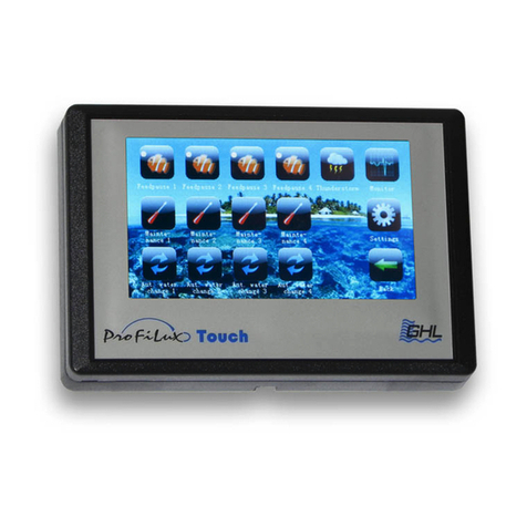
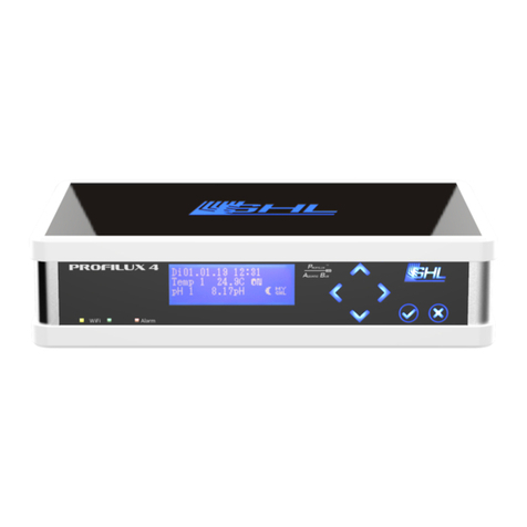
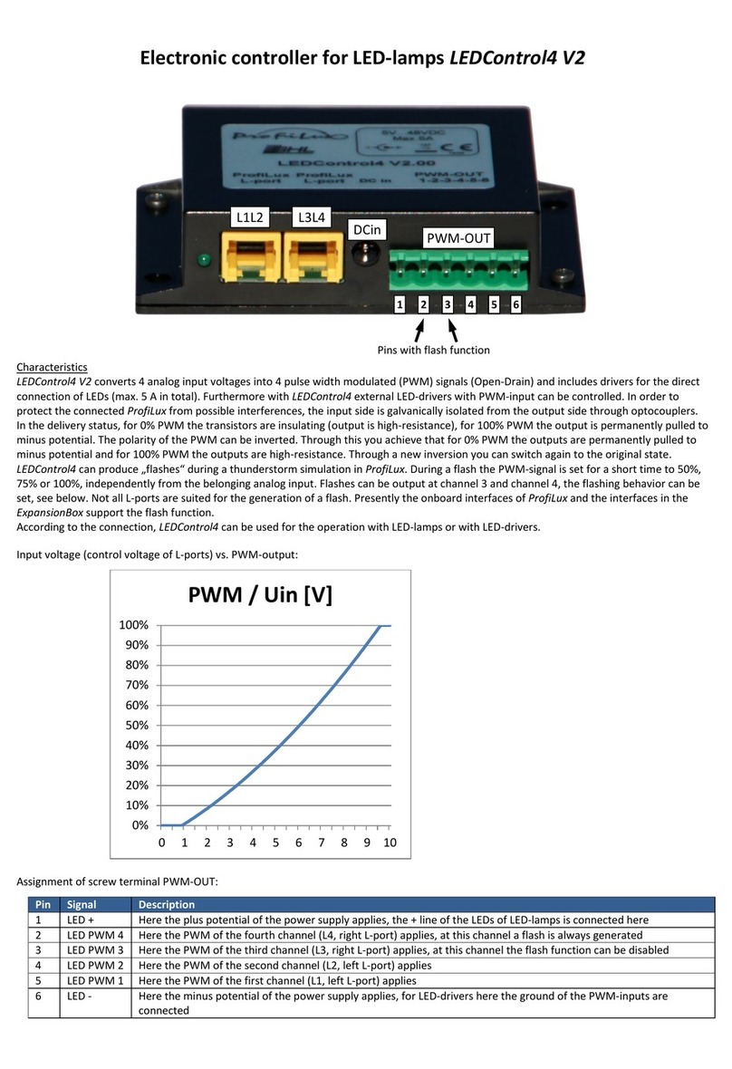
GHL ProfiLux 4 Operating instructions

ProfiLux 4
Programming Guide
Valid from firmware-version 7.02
As of 2017-02-06

ProfiLux 4 Programming Guide
EN 2017-02-06 2
Table of Contents
PREFACE.................................................................................................................................................................... 6
GET THE MOST OUT OF YOUR GHL PRODUCT ..........................................................................................................................6
ABOUT THIS PROGRAMMING GUIDE.......................................................................................................................................6
SAFETY INSTRUCTIONS .........................................................................................................................................................7
INTENDED USE ...................................................................................................................................................................7
1FUNCTIONALITY AND OPERATING CONCEPT ..................................................................................................... 7
1.1 FUNCTIONALITY OF THE P4.......................................................................................................................................7
1.2 OPERATING CONCEPT ...........................................................................................................................................10
1.3 EXAMPLES OF SETTINGS.........................................................................................................................................10
1.3.1 How to setup Temperature control .........................................................................................................10
1.3.2 How to set the Illumination? ...................................................................................................................10
1.3.3 How to set the Level control? ..................................................................................................................11
1.3.4 How to set the Current pump control? ....................................................................................................11
1.3.5 How to set Dosing or Timer activities? ....................................................................................................11
1.4 FEATURES /RESOURCES ........................................................................................................................................11
1.5 NUMBERING AND DISPLAY OF RESOURCES ................................................................................................................11
2CLOCK.............................................................................................................................................................. 12
2.1 TIME &DATE,DCF ..............................................................................................................................................12
2.2 REMINDERS.........................................................................................................................................................13
2.3 TIMERS ..............................................................................................................................................................14
2.4 DOSING PUMP.....................................................................................................................................................17
2.5 LOCATION...........................................................................................................................................................19
3ILLUMINATION ................................................................................................................................................ 19
3.1 ILLUMINATION RUN ..............................................................................................................................................20
3.2 COPY AN ILLUMINATION RUN USING GCC.................................................................................................................21
3.3 TIME SHIFT WITH GGC ..........................................................................................................................................21
3.3.1 Time shift during clouds ..........................................................................................................................21
3.3.2 Time shift for Illumination Run ................................................................................................................22
3.4 MANUAL ILLUMINATION........................................................................................................................................23
3.5 CLOUDS..............................................................................................................................................................24
3.6 MOON ...............................................................................................................................................................24
3.7 RAINY DAYS ........................................................................................................................................................25
3.8 BURNING-IN........................................................................................................................................................25
3.9 OPERATING HOURS...............................................................................................................................................26
3.10 THUNDERSTORMS ................................................................................................................................................26
3.11 TEMPERATURE-DEPENDENT LIGHT REDUCTION ...........................................................................................................27
3.12 VARIABLE ILLUMINATION .......................................................................................................................................29
3.13 MITRAS LIGHTBAR................................................................................................................................................29
3.14 LIGHT DEMO........................................................................................................................................................29
3.15 TIME LAPSE .........................................................................................................................................................30
3.16 ACCLIMATION......................................................................................................................................................30
3.17 SHIFT CURVES......................................................................................................................................................31
4EXTRAS ............................................................................................................................................................ 31
4.1 MAINTENANCE ....................................................................................................................................................31
4.2 FEEDING PAUSE ...................................................................................................................................................33
4.3 INTERNAL TIME....................................................................................................................................................34
4.4 INFO &SUPPORT .................................................................................................................................................34
4.5 CURRENT ............................................................................................................................................................34

ProfiLux 4 Programming Guide
EN 2017-02-06 3
4.5.1 Nocturnal Change....................................................................................................................................35
4.5.2 Group Settings .........................................................................................................................................35
4.5.3 Pump Settings..........................................................................................................................................39
4.6 EHEIM................................................................................................................................................................39
4.7 DISPLAY..............................................................................................................................................................40
4.8 MEASUREMENT DATA...........................................................................................................................................40
4.9 LANGUAGE..........................................................................................................................................................42
5SENSOR SETTINGS ........................................................................................................................................... 42
5.1 ACTIVITY.............................................................................................................................................................43
5.2 NOMINAL VALUE..................................................................................................................................................43
5.3 OPERATION HOURS ..............................................................................................................................................45
5.4 HYSTERESIS .........................................................................................................................................................45
5.5 ALARM...............................................................................................................................................................46
5.6 NOCTURNAL CHANGE............................................................................................................................................48
5.7 SUMMER SWITCHING............................................................................................................................................49
5.8 THERAPY ............................................................................................................................................................50
5.9 CALIBRATION.......................................................................................................................................................50
5.9.1 General ....................................................................................................................................................51
5.9.2 Calibration Tolerance ..............................................................................................................................51
5.9.3 Overview of the Calibration values..........................................................................................................52
5.9.4 Temperature Sensor (Analog)..................................................................................................................52
5.9.5 pH Sensor.................................................................................................................................................53
5.9.6 Redox-Sensor ...........................................................................................................................................53
5.9.7 Conductivity.............................................................................................................................................54
5.9.8 Oxygen Sensor .........................................................................................................................................55
5.9.9 Control of Sensor calibration ...................................................................................................................56
5.10 DISPLAY..............................................................................................................................................................57
5.11 COOLING DIFFERENCE ...........................................................................................................................................58
5.12 EXTENSION..........................................................................................................................................................58
5.13 MEASUREMENT RANGE .........................................................................................................................................59
5.14 DENSITY OFFSET ..................................................................................................................................................59
5.15 1-10 VMAX.AT…................................................................................................................................................59
5.16 CURRENT ACTUAL VALUE .......................................................................................................................................60
5.17 OPERATION MODE CONTROLLER .............................................................................................................................60
5.18 SIGNAL FILTER .....................................................................................................................................................61
6LEVEL ............................................................................................................................................................... 61
6.1 CONTROL............................................................................................................................................................63
6.1.1 Operation Mode ......................................................................................................................................63
6.1.2 Maximum on-time...................................................................................................................................64
6.1.3 Automatic Error reset ..............................................................................................................................65
6.1.4 Sensor select ............................................................................................................................................65
6.2 INPUT ................................................................................................................................................................65
6.2.1 Reaction Time ..........................................................................................................................................65
6.2.2 Input Inverse............................................................................................................................................65
6.3 ERROR RESET ......................................................................................................................................................66
6.4 DIAGNOSTIC ........................................................................................................................................................66
6.5 START WATER CHANGE .........................................................................................................................................66
7FLOW............................................................................................................................................................... 66
7.1 ALARM THRESHOLD ..............................................................................................................................................67
7.2 CALIBRATION.......................................................................................................................................................67
7.3 NOMINAL VALUE..................................................................................................................................................67
7.4 CONNECTED AT LEVEL-SENSOR................................................................................................................................67

ProfiLux 4 Programming Guide
EN 2017-02-06 4
8SYSTEM ........................................................................................................................................................... 68
8.1 FACTORY SETTINGS...............................................................................................................................................68
8.2 PIN ...................................................................................................................................................................68
8.3 SOCKET OUTLET FUNCTION ....................................................................................................................................68
8.4 1-10 VINTERFACE ...............................................................................................................................................71
8.5 PROGRAM LED....................................................................................................................................................73
8.6 COMMUNICATION ................................................................................................................................................74
8.7 ALARM...............................................................................................................................................................74
8.8 VIRTUAL PROBES..................................................................................................................................................75
8.9 DIGITAL POWERBARS ............................................................................................................................................76
8.10 CONFIGURE PTC ..................................................................................................................................................78
8.11 DALI .................................................................................................................................................................78
8.12 DIGITAL INPUT.....................................................................................................................................................79
8.13 MYGHL..............................................................................................................................................................79
9PROGRAMMABLE LOGIC.................................................................................................................................. 80
Below is the menu structure of the ProfiLux 4. These are the options available to you when
you operate the P4 through the device’s Control Pad. (This structure is also similar to the
layout seen in the PC-Software, GHL Control Center (GCC).

ProfiLux 4 Programming Guide
EN 2017-02-06 5
Clock
TIme & Date,
DCF
Reminders
Timers
Dosing
pump
Location
Illumination
Illumination
run
Manual
illumination
Clouds
Moon
Rainy days
Burning-in
Operating
hous
Storms
Temperature
-dependent
lightreductio
n
Variable
Illumination
Mitras
Lightbar
Lightdemo
Time lapse
Acclimation
Shift curves
Extras
Maintenance
Feeding
pause
Internal time
Info &
Support
Current
Eheim
Display
Measuremen
t data
Language
Sensor
settings
Activity
Nominal
value
Operation
hours
Hysteresis
Alarm
Nocturnal
change
Summer
switching
Therapy
Calibration
Display
Cooling
difference
Extension
Measuremen
t range
1-10 V maxi.
at
Density
offset
Current
actual value
Operation
mode control
Signalfilter
Level
Control
Input
Diagnostic
Start water
change
Error reset
System
Factory
settings
PIN
Socket outlet
function
1-10 V
interface
Program LED
Communikati
on
Alarm
Virtual
probes
Digital
powerbars
Configure
PTC
DALI
Digital inputs
myGHL

ProfiLux 4 Programming Guide
EN 2017-02-06 6
Preface
This manual is a supplement to the ProfiLux® 4Instruction manual. This Programming
Guide is based on these operating instructions and cannot replace them in any
circumstances.
Get the Most out of your GHL Product
GHL products are well-equipped with simple and intuitive features. In order to get the most
out of our products, we recommend you read our Programming Guide and Instruction
Manual together. Doing so will provide you with the most profound details for using our
product. These documents can be downloaded from our website’s download area (Support-
>Downloads). Visit our homepage at www.aquariumcomputer.com , our Support forum or
visit us on Facebook to become a GHL-Product expert and fully utilize the full range of
functions offered from your device!
About this Programming Guide
The information provided by this guide is primarily based on setup and configuration via the
ProfiLux 4 display. When you configure the ProfiLux 4 via GHL Control Center, setup will slightly
differ from the descriptions shown in this guide. Individual settings are however, identically
displayed on the device and GHL Control Center.
Please read these instructions carefully before operating the ProfiLux 4.
GHL products are built with maximum security and safety in mind. However, product safety
for this device can only be guaranteed if you follow these guidelines.
Anyone who uses this device must become familiar with the following safety instructions and
the operation of the device.
Failure to follow these instructions will void any warranty claims.
In this manual, the following symbols are used:
TIP
General note, tip or advice.

ProfiLux 4 Programming Guide
EN 2017-02-06 7
WARNING
Important note for operation, to avoid damage to the equipment, and for
your safety.
Safety Instructions
WARNING
This equipment must not be used:
By small children and vulnerable persons with limited physical,
sensory or mental capabilities.
By people who are unfamiliar with the functions of this product.
Intended Use
The ProfiLux 4 is exclusively for use in the domestic area. Only GHL accessories may be
connected directly to the ProfiLux 4 controller.
Make sure to keep the device away from splashing water, moisture or other liquids.
This controller is for monitoring and controlling aquarium functions and is exclusively for
indoor usage. ProfiLux 4 must be kept dry at all times.
For your own safety, please read the hazard prevention and safety instructions in the
chapters that follow. These precautionary tips are also found in the ProfiLux 4 Instruction
Manual.
1Functionality and Operating Concept
1.1 Functionality of the P4
The following graphic gives you a rough overview of the functionality of the ProfiLux 4
Aquarium Controller. It also shows the interaction of the different system components.
DANGER
Warning that non-compliance can result in injury or damage to the device.

ProfiLux 4 Programming Guide
EN 2017-02-06 8
DANGER
Please note the following:
The ProfiLux 4 Controller and its components (ProfiLux 4 System)
perform measurement, control, and control tasks based on your
settings.
There is no plausibility check of the settings you have made.
The controller's factory settings must be adapted to the
requirements of your aquarium.
You are solely responsible for the plausibility of your computer
settings and its system components.
The ProfiLux 4 Controller cannot replace the lack of expertise
required for the maintenance and maintenance of an aquarium or
terrarium.
Never leave your aquarium unsupervised for an extended amount of
time.
The ProfiLux System can help you with a large number of tasks and
display error conditions - but it cannot replace regular personal
supervision and control.
The maximum period of time without personal supervision depends
on how long your aquarium / terrarium can survive even in the event
of a fault without significant damage.
Always remember that technologies can fail and therefore,
malfunctions can never be ruled out!
Power failures, incorrect settings, damage (For example, by water or
overvoltage) or simply an unexpected operating situation can lead to
fatal damage.
The manufacturer disclaims any liability for (consequential) damages
or losses which might arise in connection with the use of the ProfiLux
System as legally permissible.

ProfiLux 4 Programming Guide
EN 2017-02-06 9
The diagram shows an example of the functionality of the ProfiLux System.
Sensors that are used for measuring various values such as Temperature, humidity, etc., are
connected to either the ProfiLux 4 or to corresponding ProfiLux Expansion Cards. Each of these
sensors are assigned to a control circuit where parameters such as Set-point, hysteresis,
nocturnal change, etc., can be set.
With the desired values and settings set, each sensor can then be assigned to control a
powerbar socket. For example, assigning a temperature sensor to a powerbar socket will
result in that socket switching on/off based on the set probe conditions.

ProfiLux 4 Programming Guide
EN 2017-02-06 10
1.2 Operating Concept
The operating concept of the ProfiLux computer strictly differs between two sets of settings:
Settings of functions such as e.g. pH set point, illumination run of a luminaire or
behavior of pumps
Settings of hardware such as the behavior of a switch socket (if this switching socket is
assigned to a lighting, a timer or a temperature sensor) or the behavior of a 1-10 V
interface (this interface should be assigned to a lighting or a pump)
This concept is extremely flexible because a function can be changed largely independently
of the hardware assigned to it and vice versa the hardware can be changed largely
independently of the function.
This concept allows you, e.g. to select a different socket for switching your tubular heater,
while the corresponding temperature settings can remain unchanged.
1.3 Examples of Settings
For a better understanding, take a look at some setting examples that are commonly used.
1.3.1 How to setup Temperature control
1. Setting the function: Set the desired set-point temperature, see also Sensor Settings->
Nominal value.
2. Setting the hardware: Set the switch socket outlet (socket) to switch the heating
element, the substrate heater and the cooling system (if present). See also System->
Socket outlet function.
1.3.2 How to set the Illumination?
1. Setting the function: Set the illumination run as needed, see also Sensor Settings->
Nominal value.
2. Setting the hardware: Set which switch socket outlet (for non-dimmable luminaires),
also see under System-> Socket outlet function, or which 1 - 10 V interface (for
dimmable luminaires), also see under System-> 1- 10 V interface, or whether the Mitras
Lightbar interface (when controlling a Mitras Lightbar) shall respond to this
illumination run.
TIP
When creating a command, it is useful to set the function first.

ProfiLux 4 Programming Guide
EN 2017-02-06 11
1.3.3 How to set the Level control?
1. Setting the function: Set the operating mode and the behavior of the level sensor, also
see under Level-> Control.
2. Setting the hardware: Set which switch socket outlet (socket) is to be switched from
the level control, see also under System-> Socket outlet function.
1.3.4 How to set the Current pump control?
1. Setting the function: Set the pump groups and the current pumps, see also under
Extras-> Current.
2. Setting the hardware: Set which switch socket outlet (for non-speed-variable pumps),
see also System-> Socket outlet function, or which 1-10 V interface (for speed-variable
pumps), and see also under System -> 1-10 V Interface should react to the Pump.
1.3.5 How to set Dosing or Timer activities?
1. Setting the function: First set the desired timer or dosing pump (note: only GHL Dosing
Pump Unit 1st generation, GHL Doser 2 is controlled via PAB!), see also under Clock->
Timers or under Clock-> Dosing pump.
2. Setting the hardware: Set which switch socket outlet (socket) is to be controlled by this
timer or dosing pump, see also under System-> Socket outlet function.
1.4 Features / Resources
The functional range of your ProfiLux 4 and, if applicable, your ProfiLux System is determined
by the available Expansion Cards, sensors, PAB devices and LED lights.
The total of all available inputs and outputs in the ProfiLux system is referred to as
resources.
1.5 Numbering and Display of Resources
All resources of the system are serially numbered by the ProfiLux Controller and this is always
carried out the same way.
The resources of the ProfiLux are numbered firstly, followed by the respective PAB devices in
order of their assignment such as Power Bars, Expansion Boxes, etc.
The numbering always starts with the internal resources of the ProfiLux, followed by the
resources of the module cards in the expansion slots according to their order in the slots of
the ProfiLux.
Then the resources of the first found and assigned PAB device will follow, after that the
resources of the second PAB device, etc.

ProfiLux 4 Programming Guide
EN 2017-02-06 12
2Clock
Use the clock feature to make changes to all time-related settings. ProfiLux 4 uses the
astronomical hour count which divides the day into 24 h.
Two clocks are running the ProfiLux 4.
The first clock is a so-called real-time clock (RTC). It shows the actual ("our") time. This is also
the time normally seen on the display. In the event of a power failure, this clock runs on a
battery-backup.
The second clock runs in the device (internal). This internal clock controls the automatic
processes such as dimming, nocturnal decrease, timers, etc.
By default, both clocks run in sync with each other, except when the actual time (e.g.,
automatic or manual winter time / summer time) is adjusted. Then the internal clock is not
adjusted immediately, but within the set days. For example, a setting of 10 days results in
60:10 = 6 minutes daily.
2.1 Time & Date, DCF
First you will be asked if you want to use DCF (external radio clock receiver, available as an
accessory).
If you confirm with Yes, the time received by the radio receiver is used. If the reception is
sufficient, the setting of the date and time is superfluous, they are updated automatically.
If you are not using DCF, you can now optimize the clock accuracy by entering a correction per
day (from -59 s to 59 s). At 0 s (default setting) the clock runs without correction, otherwise
the adjusted second number is added (or subtracted) once per day.
Then you have the option to determine whether the ProfiLux clock should change between
the normal time (CET) and the summer time (CEST).
If this shall not be the case, then in your aquarium only the normal time will be valid (i.e. in
summer the clock will go wrong by one hour). This makes possibly sense if you would like to
avoid the clock change for your fishes and plants.
If you want a changeover, you can still adjust how many days the changeover is to be made.
If you use DCF, this smooth time adaptation starts beginning from the time of the CET-CEST-
change. If you don’t use DCF, then the time can be changed manually by one hour.

ProfiLux 4 Programming Guide
EN 2017-02-06 13
In this case also, the internal clock will be adjusted slowly within the set days. With this, you
are given the opportunity to spread this one hour over several days and you will have a
smooth time change.
After this you can then set the date and time manually.
When you save the time settings, you will be asked if you want to update the internal time
(see above).
If you confirm with Yes, the internal time is immediately set to the new time, otherwise the
internal time will be adjusted smoothly as explained above.
For initial time setting you should confirm with Yes. If you want to change clock due to
summer time, confirm with No.
2.2 Reminders
ProfiLux 4 can remind you of activities to be performed.
After a certain adjustable time (in days), the reminder text is displayed on the ProfiLux 4,
alternating with the standard display.
The reminder is displayed until you mark it as done. If you have set a repeated reminder, the
reminder will be displayed again after the new expiration time.
For example, a reminder can be set to be displayed every month to indicate a filter must be
replaced.
A single and repeating reminder can be set to display the desired text when requested.
After setting the reminder(s), ProfiLux 4 will display as a confirmation when the next reminder
will come about.
You can enter up to 16 reminder texts.
Note
The DCF signal for the radio clock is not always present.
Therefore it could happen that sometimes no reception is possible.
The internal clock continues to run and is synchronized again at the next
reception (possible minor deviations are corrected). Therefore DCF can also
be used with only occasional reception.

ProfiLux 4 Programming Guide
EN 2017-02-06 14
Select the reminder (1 - 16) first.
Select whether the reminder should be enabled -> RETURN
If this reminder is currently up-to-date, you can mark it as done, it will not be
displayed any further.
If you have activated this reminder with Yes, you can set whether you want to be
reminded repeatedly.
You can then enter how many days you want to be reminded.
Then enter the reminder text.
Press the top arrow button on the control panel. The letter Aappears. Press again to
display the letter B, press again to display C, and so on. The letters appear according
to their order in the alphabet. If you want to go back a letter (for example from Cto B),
press the lower arrow key.
Press the left and right arrow keys to move the cursor to the right and left, and enter
additional characters or spaces.
When the text is finished, press RETURN and press YES. Safe with -> RETURN
After saving, ProfiLux 4 shows a confirmation when the next reminder is pending.
2.3 Timers
ProfiLux 4 has 32 freely programmable timers whose function you can adjust as described
below. The switch socket outlets (hardware), which are to react to the switching operations,
can be assigned as described under System-> Socket outlet function.
After selecting the timer that you want to program, the switching mode (function) needs to
be set. The following options can be selected:
Normal
This mode is used to program longer switching times (accuracy 1 minute).
The switching time (Duration) is set by entering the switch-on time and the switch-off time.
Short time
NOTE
You can use a timer for dosing purposes, but for more sophisticated
functions, we recommend using the dosing pump control, see
Clock ->Dosing pump.

ProfiLux 4 Programming Guide
EN 2017-02-06 15
With this setting, short switching times (1s to 300s, accuracy 1s) can be realized. The
switching time is set by entering the switch-on time and duration.
Automatic dosing
As many Dosings per day will take place as it has been set before under Switching cycles per
day. The time points of the dosings are calculated automatically (they are spread evenly
throughout the day). The switching duration is calculated automatically on the basis of the
Flow rate of the pump and the Rate per dosing (see below).
Manual dosing
As many Dosings per day will take place as it has been set before under Switching cycles per
day. The time points of the dosings can be defined explicitly afterwards. The switching
duration is calculated automatically on the basis of the Flow rate of the pump and the Rate per
dosing (see below).
Event start
The timer initiates an operation such as e.g. A water change, see also under ->Level. Enter the
start time only.
Cyclic
This mode allows very special switching sequences. Please note that this mode can only be
selected and set via our PC program GCC (GHL Control Center)!
In this mode, the timer is switched on and off alternately, always after a certain waiting time
has elapsed.
The wait time after which is switched on is determined by random generator within the limits
of the minimum waiting time and maximum waiting time. If the waiting time should always be
the same, enter the same value for both times. The waiting time after which is switched off is
also determined by a minimum waiting time and a maximum waiting time.
One cycle consists of 1 to 4 pairs of switch-on and switch-off waiting times. After the last
switch-off of the cycle, the cycle starts from the beginning. All waiting times are adjustable in
the range from 1 s to 65535 s.
Example for a cycle with 2 switch-ons and switch-offs:
Min. wait time
Max. wait time
Result
Switch on 1
10s
20s
After 10 to 20 seconds is switched on
Switch off 1
60s
60s
After 60 seconds is switched off
Switch on 2
300s
1000s
After 300 to 1000 seconds is switched on

ProfiLux 4 Programming Guide
EN 2017-02-06 16
Switch off 2
1s
30s
After 1 to 30 seconds is switched off
Cycle starts from the beginning
After that, you can enter the number of Switching cycles per day (0 up to 8; 0 means that this
timer is not active)
After setting the switching cycles, enter the Day mode:
Days of week
Here you can set the weekdays to be switched. A marked box means "Switching active on this
weekday", an empty box means "inactive ".
Interval of days
Here, the number of days after which the switching cycle is to be repeated is set, 1 day
means a daily switching cycle. After that you can set in how many days the switching shall be
started.
If you have selected a dosing switching mode, you must also enter the flow rate in ml /
minute.
Here, the actual pump power is needed. Based on this information, ProfiLux 4 calculates the
switch-on times of the dosing pump.
Changing this setting does not affect the pump performance - this is predefined by the pump
mechanism!
For an automatic dosing, you must also adjust the Rate per dosing.
A timer can activate a feeding pause, see at Extras-> Feeding pause.
Instructions for Dosing
The dosing amount per day corresponds to the Dosings/day and Rate/Dose.
For example, 4 doses per day with 10ml per dose will result in 40ml being
dosed per day.
Alternatively, you can also use a timer or a controller (e.g. pH-value or
conductivity) to control a dosing pump.
Due to tolerances, a pump’s flow rate on the data sheet can deviate from
the reality. To achieve the highest possible level of dosing accuracy, we
recommend you measure the actual flow rate of a pump (let pump run for 1
minute and measure the quantity of fluid pumped in this time) and set the
result of this measurement in Flow rate.

ProfiLux 4 Programming Guide
EN 2017-02-06 17
2.4 Dosing Pump
ProfiLux 4 has 16 freely programmable dosing pump controllers, whose function you can
adjust as described below. The switching outputs (hardware) which shall react to the
switching processes can be assigned as described under System-> Socket outlet function.
Select the dosing pump you want to program and then set the Switching mode. Choose from
the following options:
1. Automatic dosing:This mode is suitable if you want to dose a certain amount of the
same quantity evenly over a certain time. A maximum of 150 doses per day are
possible
2. Manual dosing: This mode is suitable if you want to dose a certain amount at fixed
times during the day. For example, at 8:00 o'clock, dose 35 ml of XY. A maximum of 8
doses per day are possible.
Furthermore, you can determine whether you want to dose on specific weekdays or daily
intervals.
Day modes:
Days of week
Here, you can set the weekdays at which the switching should be carried out. Use the right
arrow key to select the checkboxes, to move on downwards press arrow down. A marked box
means "Switching on this day of week active", an empty box means "inactive". Confirm the
selection with ->RETURN.
Interval of days
Here, you can set the number of days by which the switching cycle/number of dosages are to
be repeated. 1 day means daily dosage. The maximum daily interval is 200 days. Be sure to
set the number of days until the switching/dosing shall start.
After that, enter the Flowrate of the Pump in ml/minute. Based on this information, ProfiLux 4
calculates the switch-on times of the dosing pump.
Changing this setting does not affect the pump performance - this is predefined by the pump
mechanism!
Automatic dosing
Set the number of doses per day. Use the arrow keys on the control panel to move the
cursor to the right or left. Enter numbers using the upper arrow key (counts up). Use

ProfiLux 4 Programming Guide
EN 2017-02-06 18
the lower arrow key to count back. Once you have entered the desired number,
confirm with ->RETURN. Up to 150 dosages are possible, 0 = No dosage.
Decide on which weekdays the dosages should take place or select the daily interval if
a dosing is to take place every day or every 2 days ... etc.
Enter the Flow rate of the dosing pump ->RETURN
Enter the dosing amount Rate per dosing ->RETURN
The dosing time points are calculated automatically (they are distributed evenly throughout
the day). The duration of the dosage is calculated automatically by means of the Flow rate of
the pump and the Rate per dosing (See below).
Manual dosing
Set the number of doses per day. A maximum of 8 dosings per day are possible -
>RETURN
Decide on which Days of week the dosages should take place or select the Interval of
days if a dosing is to take place every day or every 2 days ... etc. The maximum daily
interval is 200 days (see below).
Enter the flow rate of the dosing pump ->RETURN
Specify the time at which the first switching / dosing should take place
Enter the dosing amount Rate per dosing ->RETURN
Proceed with the further desired switching operations as with switching operation 1
There are as many switching cycles per day as was set at dosages per day before. The time
points of the dosage can be defined explicitly in the following. The switching time is
calculated automatically by means of the Flow rate of the pump and the Rate per dosing. (see
below).
If you have selected Automatic dosing, the first dosing of the day is usually made at 0:00. With
Always dose at (this time) you have the possibility to determine the time of the first dosing. All
other doses are distributed throughout the day
The following features are only available via GHL Control Center, Web Interface, App and cloud
service myGHL:
The dosing pump control has a level monitoring. When the pump is active ProfiLux 4
calculates the new filling level.
For this purpose, the Capacity of the container as well as the minimum amount must be
entered.

ProfiLux 4 Programming Guide
EN 2017-02-06 19
If Alarm when below is activated ProfiLux 4 outputs an alarm. Before an alarm is issued
ProfiLux 4 will give a warning.
If the container is refilled, the replenished quantity can be entered, a possible alarm will be
reset if there is sufficient refilling.
2.5 Location
The coordinates (Longitude and Latitude) of your location can be entered here. This
information will be used for further simulations in the future.
From the factory, this is 49.4 ° N and 7.8 ° E - the coordinates of Kaiserslautern in Germany -
the production location of your ProfiLux 4.
3Illumination
This menu contains all lighting-related settings and functions.
ProfiLux 4 can control 32 dimmable or non-dimmable lamps independently. Lighting units
can be switched via our powerbars. Dimmable lighting units can be also controlled via the 1-
10V interfaces. The dimmable LED Mitras Lightbar is controlled via its own digital interface.
Dimmable tubular lightbars are controlled by L1 (or L3, L5, etc.) as standard. It controls both
tubes of that lightbar.
You also have the option to simultaneously dim tubular lightbars.
Instructions for Dosing
The dosing amount per day corresponds to the Dosings/day and Rate/Dose.
For example, 4 doses per day with 10ml per dose will result in 40ml being
dosed per day.
Alternatively, you can also use a timer or a controller (e.g. pH-value or
conductivity) to control a dosing pump.
Due to tolerances, a pump’s flow rate on the data sheet can deviate from
the reality. To achieve the highest possible level of dosing accuracy, we
recommend you measure the actual flow rate of a pump (let pump run for 1
minute and measure the quantity of fluid pumped in this time) and set the
result of this measurement in Flow rate.

ProfiLux 4 Programming Guide
EN 2017-02-06 20
You can set the illumination run for each lighting individually. This makes it possible to
achieve effects like sunrise or moonlight.
3.1 Illumination Run
Please select which lighting is to be edited (Illumination to edit?). After selecting a lighting, you
can set the type of the luminaire, dimmable and non-dimmable.
It is also necessary to specify whether the automatic is to be switched on (Automatic on?). If
this is not the case, this lighting is in manual mode. Select whether you want a temperature-
dependent light reduction.
Enter the number of dim-points (for dimmable luminaires) or the switch-times (for non-
dimmable luminaires) for which you want to adjust the brightness (up to 24)
If you have selected a dimmable luminaire, please set the following for each dim-point:
Time –At this time, the luminaire shall have the brightness to be set subsequently
Light intensity (0% - 100%) –Brightness of the light at this time
If you have selected a non-dimmable luminaire, please set the following for each dimming
time:
Switch on –The light is switched on at this time
Switch off –The light is switched off at this time
Then select which simulations should affect this lighting process and save the settings with
Yes ->RETURN.
TIP
If required, you can retrofit additional 1-10 V interfaces with ProfiLux
Expansion Cards, PLM-4L or PLM 2L4S.
NOTE
The brightness curve between the individual dim-points are calculated
automatically.
Other manuals for ProfiLux 4
2
Table of contents
Other GHL Controllers manuals
Popular Controllers manuals by other brands

SmartPID
SmartPID M5 PRO quick start guide

Technische Alternative
Technische Alternative UVR16x2***-D Programming guide

Santerno
Santerno SINUS PENTA Series Guide

DH Instruments
DH Instruments PPCH - V1.01 Operation and maintenance manual

Digital Monitoring Products
Digital Monitoring Products X1 Series quick start guide

Mitsubishi
Mitsubishi FX2N-4AD-PT user guide