manuals.online logo
Brands
  1. Home
  2. •
  3. Brands
  4. •
  5. alre
  6. •
  7. Controllers
  8. •
  9. alre KTRTB-251.108 User manual

alre KTRTB-251.108 User manual

1Stand 12.2017 (14/096) 5 21 668 01
KTRTB - 251.108
Elektronischer Klimaregler für 2 - Rohr - Leitungssysteme
Electronic controller for the control of the heating/ cooling operations performed by 2 - pipe systems
Régulateur pour le contrôle des opérations de chauage / refroidissement exécutées par des systèmes à deux tubes
Sicherheitshinweis!
Dieses Gerät darf nur durch eine Elektrofachkraft geönet und gemäß dem entspre-
chenden Schaltbild im Gehäusedeckel/in der Bedienungsanleitung installiert werden.
Dabei sind die bestehenden Sicherheitsvorschriften zu beachten.
Achtung! Der Betrieb in der Nähe von Geräten, welche nicht den EMV- Richtlinien ent-
sprechen, kann zur Beeinflussung der Gerätefunktion führen. Nach der Installation ist
der Betreiber, durch die ausführende Installationsfirma, in die Funktion und Bedienung
der Regelung einzuweisen. Die Bedienungsanleitung muss für Bedien- und Wartungs-
personal an frei zugänglicher Stelle aufbewahrt werden.
Safety information!
Expert electricians only may open this device in due compliance with the wiring diagram
shown in the housing cover/on the housing/ represented in the corresponding operat-
ing instructions. All expert electricians charged with the execution of such works must
comply with the relevant safety regulations currently operative and in force.
Caution: The operation of the controller in the vicinity of other devices that do not
comply with the EMC directives may aect its functions. The company charged with
the installation of the device must, after the completion of the installation works, instruct
the user of the control system into its functions and in how to operate it correctly. These
operating instructions must be kept at a place that can be accessed freely by the oper-
ating and/or servicing personnel in charge.
1. Anwendung
Dieser Regler wurde speziell zur Heiz-/ Kühlregelung in 2-Rohr -Leitungssysteme für
Hotel-, Wohn- und Geschäftsräume entwickelt und kann bis zu 5 Ventilantriebe (24 V ~,
stromlos geschlossen) ansteuern. Gegebenenfalls benötigte Temperaturbegrenzungen
müssen zusätzlich installiert werden. Für andere, vom Hersteller nicht vorherzusehen-
de Einsatzgebiete, sind die dort gültigen Sicherheitsvorschriften zu beachten. Eignung
hierfür siehe Punkt8. Gewährleistung.
2. Funktionen
Der KTRTB erfasst mit einem internen Fühler die Raumtemperatur und aktiviert bei Ab-
weichung zum eingestellten Sollwert die Heizung bzw. Kühlung. Durch die Verwendung
eines Triacs als Schaltelement statt eines Relais /Bimetalls entstehen keine Schaltge-
räusche im Betrieb.
2.2 Energiesparfunktion (ECO Betrieb)
Durch einen externen Kontakt (ECO Kontakt) kann die Energiesparfunktion ausgelöst
werden. Wird diese Funktion gewählt, wird im Heizbetrieb auf eine um 3K geringere und
im Kühlbetrieb auf eine um 3K höhere Temperatur geregelt. So kann bei nicht belegten
bzw. ungenutzten Räumen oder Etagen z. B. zeitgesteuert über einen Uhrenkontakt eine
zentrale Energieeinsparung realisiert werden. Mittels des Schalters 1 (siehe Punkt6.)
ist es möglich, den Regler so anzupassen, dass statt einer Temperaturabsenkung/Er-
höhung der Regler ausgeschaltet wird (Frostschutz weiterhin aktiv). Verdrahtung siehe
Punkt6.
Kontakt geschlossen = ECO Funktion bzw. AUS
Kontakt oen = Normalbetrieb
3. Anzeigen
Der Regler verfügt über zwei Lampen zur Anzeige des Regelzustandes.
Gelb = Heizen
Blau = Kühlen
1. Application
This controller has been specially devised for the control and supervision of the heating
and cooling operations performed by 2-pipe systems existing in hotel rooms, living
spaces and business premises. The device is able to trigger up to 5 valve drives (24 V,
normally closed). Where applicable, temperature limiters need to be installed in addi-
tion. Regarding other applications not to be foreseen by the manufacturer of this device,
the safety standards concerning these applications need to be followed and adhered to.
Regarding the suitability of the device for such applications, please refer to section8.
2. Functional description
The KTRTB measures, based on the data delivered by an internal sensor, the tem-
perature that exists in the related room and, in the event a deviation of the actual value
with regard to the set value is detected, triggers the activation of the heating or cooling
installation as needed. The triac switching element used in place of a relay or bimetal
relay, produces, in contrast to these components, no switching noises during the op-
eration of the device.
2.1 Heating / cooling changeover
The controller is equipped with a joint heating/cooling output, the changeover opera-
tions of which are being triggered by an external contact (changeover contact). All con-
trollers used for the management of the overall system can, based on this function, be
changed over from one central point. The control direction of the device can, by means
of the switch marked as switch No. 2 (see section6.), be adapted to the operations
triggered via this contact. As for the wiring, please refer to section6.
2.2 Energy economizing function (ECO mode)
The operation in energy economizing mode can be triggered via an external contact
(ECO contact). Selecting this mode enables to adjust to a temperature value that is by
3K lower while heating and to adjust to a temperature value that is by 3K higher while
cooling. This allows, controlled by, for example, a time contact, to save energy in all
currently unoccupied or unused rooms or floors in a centralised manner. The switch
marked as switch No.1 (see section6.) allows to adapt the controller in such a manner
that, instead of a decrease/ increase of the temperature, it is being deactivated (frost
protection function remains active). As for the wiring, please refer to section6.
Contact closed = ECO function or OFF
Contact open = normal operation.
2.1 Heiz - / Kühlumschaltung
Der Regler verfügt über einen gemeinsamen Heiz- /Kühlausgang, der über einen exter-
nen Kontakt (Change-Over - Kontakt) umgeschaltet wird. So ist es möglich, eine zen-
trale Umschaltung für alle Regler zu realisieren. Der Wirksinn kann mit dem Schalter 2
(siehe Punkt6.) an den Kontakt angepasst werden. Verdrahtung siehe Punkt6.
4. Montage / Anschluss
Auslieferungszustand oen. Montage wegen des geringen Verdrahtungsraumes auf
eine UP- Dose empfohlen, kann aber auch auf ebenem nichtleitfähigen Untergrund er-
folgen. Önen und Schließen wie in Bild 1 beschrieben. Achtung! Die zur Wand zeigen-
den, verdeckten Lüftungsschlitze dürfen nicht verschlossen werden, da dies zu einer
fehlerhaften Regelung führt.
3. Indicator lamps
Two lamps at the controller indicate its operating condition.
Yellow = Heating
Blue = Cooling
4. Mounting / Installation
The controller is, in order to facilitate its installation, delivered in opened condition.
As there is only little space available for its wiring, it is recommended to install the
device on an UP box. The device is also suited for installation on even, non- conductive
surfaces. The opening and closing of the device is realised as described in picture 1.
Caution: The hidden venting slots pointing to the wall must not be covered in any way.
Otherwise, there is danger that the control operations of the device become incorrect.
Entsorgungshinweis
Gerät nicht im Hausmüll entsorgen! Elektronische Geräte sind entsprechend
der Richtlinie über Elektro- und Elektronik- Altgeräte (WEEE-Richtlinie) über die
örtlichen Sammelstellen für Elektronik-Altgeräte zu entsorgen.
Disposal information
Do not dispose of this device through domestic waste! Electronic devices must
be disposed of in accordance with the Directive on Waste Electrical and Elec-
tronic Equipment (WEEE directive) via the local collection points for waste elec-
trical and electronic equipment.
1. Knopf abnehmen
Remove the knob
Enlever le bouton
2. Schraube entfernen
Unscrew the screw
Dévisser la vis
3. Drücken
Press / Presser
4. Ziehen
Pull / Tirer
Einstellfahne für minimalen
Temperaturwert
Pin for the setting of the
minimum temperature value
Broche pour l’ajustage
de la valeur de température
minimale
Einstellfahne für maximalen
Temperaturwert
Pin for the setting of the
maximum temperature value
Broche pour l’ajustage
de la valeur de température
maximale
Bild 1 / Picture 1 / Illustration 1
Bild 2 / Picture 2 / Illustration 2
2
ALRE-IT Regeltechnik GmbH •Richard- Tauber- Damm 10 •D - 12277 Berlin •Tel.: +49 (0) 30/ 399 84 - 0 •Fax: +49 (0)30 / 391 70 05 •[email protected] •www.alre.de
Consigne de sécurité!
Uniquement des personnes qualifiées en matière d’électricité doivent ouvrir ce dis-
positif en conformité avec le schéma des connexions représenté dans le couvercle
du boîtier/ apposé sur le boîtier/ représenté dans les notices d’instructions. Tous élec-
triciens spécialisés chargés de l’exécution de tels travaux doivent se conformer aux
prescriptions de sécurité actuellement en vigueur s’y rapportant.
Attention! L’opération du régulateur dans les environs d’autres dispositifs ne confor-
mant pas aux directives CEM peut aecter son bon fonctionnement. La société chargée
de l’installation du dispositif doit, après l’achèvement des travaux, initier l’utilisateur
aux fonctions du régulateur et à son opération correcte. Toujours garder cette notice
d’instructions à un lieu librement accessible pour les opérateurs et hommes de service.
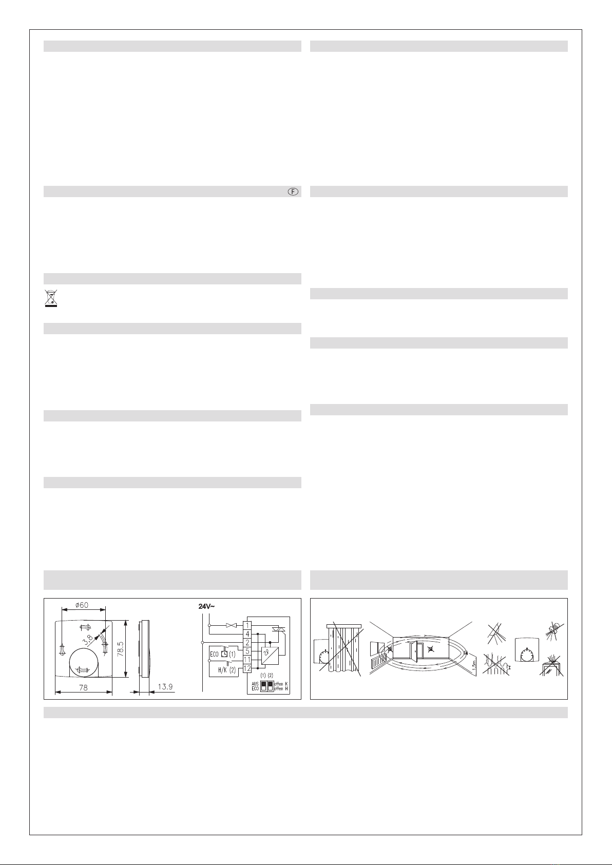
6. Maßbild und Anschluss - Schaltbilder / Dimensional drawing and
connection diagram/ Dessin coté et schéma de branchement
1. Application
Ce régulateur a été spécialement conçu pour le contrôle et surveillance des opérations
exécutées par des systèmes de chauage et de refroidissement à deux tubes existant
dans des salles ou chambres d’hôtels, des habitations ou locaux à usage commercial.
Il permet de commander un nombre de jusqu’à 5 entraînements des soupapes (24 V,
types normalement fermés). Le cas échéant, il faut installer des limiteurs de tempéra-
ture en plus. Concernant des autres applications pas à prévoir par le fabricant de ce
dispositif, les standards de sécurité se rapportant à ces applications sont à respecter.
En ce qui concerne l’aptitude du dispositif pour des telles applications, veuillez égale-
ment faire attention aux informations de garantie dans chapitre8., Garantie, dans cette
notice d’instructions.
2. Fonctionnement
Le KTRTB mesure, sur la base des données délivrées par un détecteur interne, la tem-
pérature qui existe dans le local correspondant et déclenche, dans le cas ou il détecte
une déviation de la valeur réelle vis-à - vis de la valeur de consigne préréglée, l’acti-
vation de l’installation de chauage ou de refroidissement selon besoin. L’élément de
commutation triac (thyristor triode bidirectionnel) utilisé à la place d’un relais ou d’un
relais bilame, ne produit, contrairement à ces composants, pas de bruits de commuta-
tion durant l’opération du dispositif.
2.1 Commutation chauage / refroidissement
Le régulateur est muni d’une sortie commune du type „chauage /refroidissement“
dont les opérations de commutation sont excités par un contact externe (contact de
commutation). Tous régulateurs utilisés pour le pilotage du système complet de réglage
peuvent, sur la base de cette fonction, être commutés à partir d’un point central. Le
sens d’action du dispositif peut, à l’aide du commutateur n° 2 (voir chapitre6.), être
adapté aux opérations excitées par et sur ce contact. Concernant le câblage, veuillez
vous reporter au chapitre6.
2.2 Fonction d’économie d’énergie (mode de fonctionnement ECO)
Un contact externe (contact ECO) permet de déclencher le mode de fonctionnement
économe en énergie. La sélection de ce mode de fonctionnement permet de régler la
température à une valeur qui, pendant la phase de chauage, sous - dépasse la valeur
préréglée par 3K, et, pendant celle de refroidissement, dépasse cette valeur par 3K.
Ceci permet, sur la base, par exemple, de l’utilisation d’un contact d’horloge, de faire,
à partir d’un point central, des économies d’énergie dans toutes les chambres, pièces,
locaux ou étages actuellement inoccupés ou inutilisés. Le commutateur n°1 (voir cha-
pitre6.) permet d’adapter le régulateur de telle manière qu’il soit, au lieu d’un abais-
sement ou d’une augmentation de la température, désactivé (la fonction antigel reste
active). Concernant le câblage, veuillez vous reporter au chapitre6.
Contact fermé = fonction ECO ou ARRET
Contact ouvert = fonctionnement normal
3. Indicateurs lumineux
Le régulateur est muni de deux indicateurs lumineux servant d’indiquer son état fonc-
tionnel.
Jaune = Chauage
Bleu = Refroidissement
7. Montagehinweis / Mounting information /
Précision d’installation
8. Gewährleistung / Warranty / Garantie
Die von uns genannten technischen Daten wurden unter Laborbedingungen nach allgemein gültigen Prüfvorschriften, insbesondere DIN -Vorschriften, ermittelt. Nur insoweit
werden Eigenschaften zugesichert. Die Prüfung der Eignung für den vom Auftraggeber vorgesehenen Verwendungszweck bzw. den Einsatz unter Gebrauchsbedingungen obliegt
dem Auftraggeber; hierfür übernehmen wir keine Gewährleistung. Änderungen vorbehalten.
The technical data specified herein have been determined under laboratory conditions and in compliance with generally approved test regulations, in particular DIN standards.
Technical characteristics can only be warranted to this extent. The testing with regard to the qualification and suitability for the client’s intended application or the use under service
conditions shall be the client’s own duty. We refuse to grant any warranty with regard thereto. Subject to change without notice.
Les données techniques indiquées dans cette notice d’instructions ont été déterminées sous conditions laboratoires en conformité avec des prescriptions d’essai généralement
approuvées, notamment les normes DIN. Les caractéristiques techniques ne peuvent être garanties que dans cette mesure. La vérification du dispositif en rapport à sa qualifica-
tion et appropriation pour l’application prévue ou son utilisation sous conditions de service incombe au client. Nous n’assumons aucune garantie à cet égard. Sous réserve de
modifications techniques.
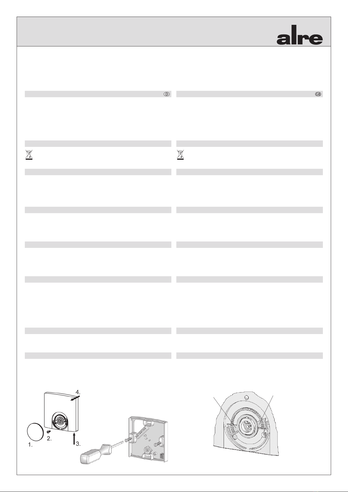
4. Installation / montage
Le dispositif est, pour faciliter son installation rapide, livré en condition ouverte. En
raison de l’espace de branchement limité à l’intérieur du boîtier du régulateur, il est
conseillé de l’installer sur une boîte de branchement encastrée. Le dispositif convient
aussi pour l‘installation sur des surfaces planes et non conductrices. L’ouverture et
la fermeture du dispositif se font comme représenté dans l’illustration1 ci-dessous.
Attention! Les fentes de ventilation cachées qui montrent vers le mur ne doivent pas
être fermées, car sinon ceci résultera dans un fonctionnement incorrect du régulateur.
5. Caractéristiques techniques
Tension de service: 24 V~, 50 Hz
Détecteur: NTC- interne
Elément de commutation: triac (thyristor diode bidirectionnel), type 1.Y
Puissance coupure: 15 W (max. 5 actionneurs,
types normalement fermés)
Plage de réglage: 5°C …30°C
Echelle: en °C
Consommation électrique: <800 mW (5 VA)
Connexions électriques: bornes à vis 0,5 mm2 …1,5 mm2
Température ambiante admissible: 0°C …40°C
Température de stockage admissible: -20°C…+ 70°C
Humidité de l’air autorisée: max. 95% d’humidité relative,
sans condensation
Matériel du boîtier et couleur: en plastique (ABS), blanc pur
(similaire à RAL 9010)
Type de protection: III
Indice de protection: IP30
Type de montage: montage mural/en saillie
(fixation à quatre trous sur une
boîte encastrée)
Classe d’ecacité énergétique: IV (contributtion à l’ecacité énergétique
du chauage saisonnier 2%)
Informations sur l‘élimination
Ne jetez pas l‘appareil dans les ordures ménagères! Les appareils électroniques
doivent être éliminés conformément à la directive relative aux déchets d‘équi-
pements électriques et électroniques (directive DEEE) via les points de collecte
locaux pour les déchets d‘équipements électriques et électroniques.
5. Technische Daten
Betriebsspannung: 24 V~, 50 Hz
Fühler: NTC-intern
Schaltelement: Triac, Typ 1.Y
Schaltleistung: 15 W (max. 5 Stellantriebe,
stromlos geschlossen)
Einstellbereich: 5°C… 30°C
Skala: °C Skala
Leistungsaufnahme: <800 mW (5 VA)
Elektrischer Anschluss: Schraubklemmen 0,5 mm2 …1,5 mm2
zulässige Umgebungstemperatur: 0°C …40°C
zulässige Lagertemperatur: -20°C…+ 70°C
zulässige Luftfeuchtigkeit: max. 95% rH, nicht kondensierend
Gehäusematerial und Farbe: ABS- Kunststo, reinweiß (ähnlich RAL 9010)
Schutzklasse: III
Schutzart: IP30
Montageart: Aufputz/ Wandmontage
(4- Loch- Befestigung auf UP- Dose)
Energieezienzklasse: IV (Beitrag zur jahreszeitbedingten
Raumheizungs-Energieezienz 2%)
5. Technical data
Operating voltage: 24 V~, 50 Hz
Sensor: NTC- internal
Switching element: triac, type 1.Y
Switching capacity: 15 W (max. 5 actuators, normally closed types)
Setting range: 5°C …30°C
Scale: °C Skala
Power consumption: <800 mW (5 VA)
Electrical connections: screw terminals 0.5 mm2
…1.5 mm2
Admissible ambient temperature: 0°C …40°C
Admissible storage temperature: -20°C…+ 70°C
Admissible air moisture: max. 95% rh., non- condensing
Housing material and colour: plastic (ABS), pure white (similar to RAL 9010)
Protection class: III
Degree of protection: IP30
Mounting method: surface / wall mounting
(4- hole fixing on UP box)
Energy eciency class: IV (contribution to seasonal space
heating energy eciency 2%)

Other alre Controllers manuals

alre CTRRS-161.000 User manual

alre

alre CTRRS-161.000 User manual

alre RFHSB-060.010 User manual

alre

alre RFHSB-060.010 User manual

alre KTRTB-211.108 User manual

alre

alre KTRTB-211.108 User manual

alre KR 80 Series User manual

alre

alre KR 80 Series User manual

alre KTRRB-042.211 User manual

alre

alre KTRRB-042.211 User manual

alre FETR 101.700 User manual

alre

alre FETR 101.700 User manual

alre HTFRD Series User manual

alre

alre HTFRD Series User manual

alre KTRRB-117.128 User manual

alre

alre KTRRB-117.128 User manual

alre JDI-22 Instruction manual

alre

alre JDI-22 Instruction manual

alre KTRRU-052.204 User manual

alre

alre KTRRU-052.204 User manual

alre KTRRN-267.014 User manual

alre

alre KTRRN-267.014 User manual

alre KTRBUu217.456 User manual

alre

alre KTRBUu217.456 User manual

alre KTBSB-112.000 User manual

alre

alre KTBSB-112.000 User manual

Popular Controllers manuals by other brands

elco CRM-2H quick start guide

elco

elco CRM-2H quick start guide

Jung FMAS16REG operating instructions

Jung

Jung FMAS16REG operating instructions

Siemens SINAMICS G130 operating instructions

Siemens

Siemens SINAMICS G130 operating instructions

Smarteh LPC-2.DI5 user manual

Smarteh

Smarteh LPC-2.DI5 user manual

GE GuardSwitch 300 Series instructions

GE

GE GuardSwitch 300 Series instructions

Lennox RG10F2-MMA manual

Lennox

Lennox RG10F2-MMA manual

GF Signet 8900 manual

GF Signet

GF Signet 8900 manual

Adaptec 52445 quick start guide

Adaptec

Adaptec 52445 quick start guide

NOVAK MONGOOSE Setup guide

NOVAK

NOVAK MONGOOSE Setup guide

Siemens SINAMICS PM240-2 Hardware installation manual

Siemens

Siemens SINAMICS PM240-2 Hardware installation manual

Crestron ZUMMESH-JBOX-DALI quick start guide

Crestron

Crestron ZUMMESH-JBOX-DALI quick start guide

Exodraft EFC16 quick start guide

Exodraft

Exodraft EFC16 quick start guide

Hanna Instruments HI 8410 instruction manual

Hanna Instruments

Hanna Instruments HI 8410 instruction manual

ADLINK Technology EPS Series user manual

ADLINK Technology

ADLINK Technology EPS Series user manual

YASKAWA SI-EP3 Technical manual

YASKAWA

YASKAWA SI-EP3 Technical manual

NOVAK GTB - PROFILE SELECTION AND PROPER GEARING manual

NOVAK

NOVAK GTB - PROFILE SELECTION AND PROPER GEARING manual

QUANT QUANT-5,5 Operation manual

QUANT

QUANT QUANT-5,5 Operation manual

Emerson Fisher SR5 instruction manual

Emerson

Emerson Fisher SR5 instruction manual

manuals.online logo
manuals.online logoBrands
  • About & Mission
  • Contact us
  • Privacy Policy
  • Terms and Conditions

Copyright 2025 Manuals.Online. All Rights Reserved.