manuals.online logo
Brands
  1. Home
  2. •
  3. Brands
  4. •
  5. Stryker
  6. •
  7. Medical Equipment
  8. •
  9. Stryker 1080 User manual

Stryker 1080 User manual

FFlluuoorroossccooppyy SSttrreettcchheerr
MMaaiinntteennaannccee MMaannuuaall
1080
EN
1080-009-002 Rev A.0 2019/09
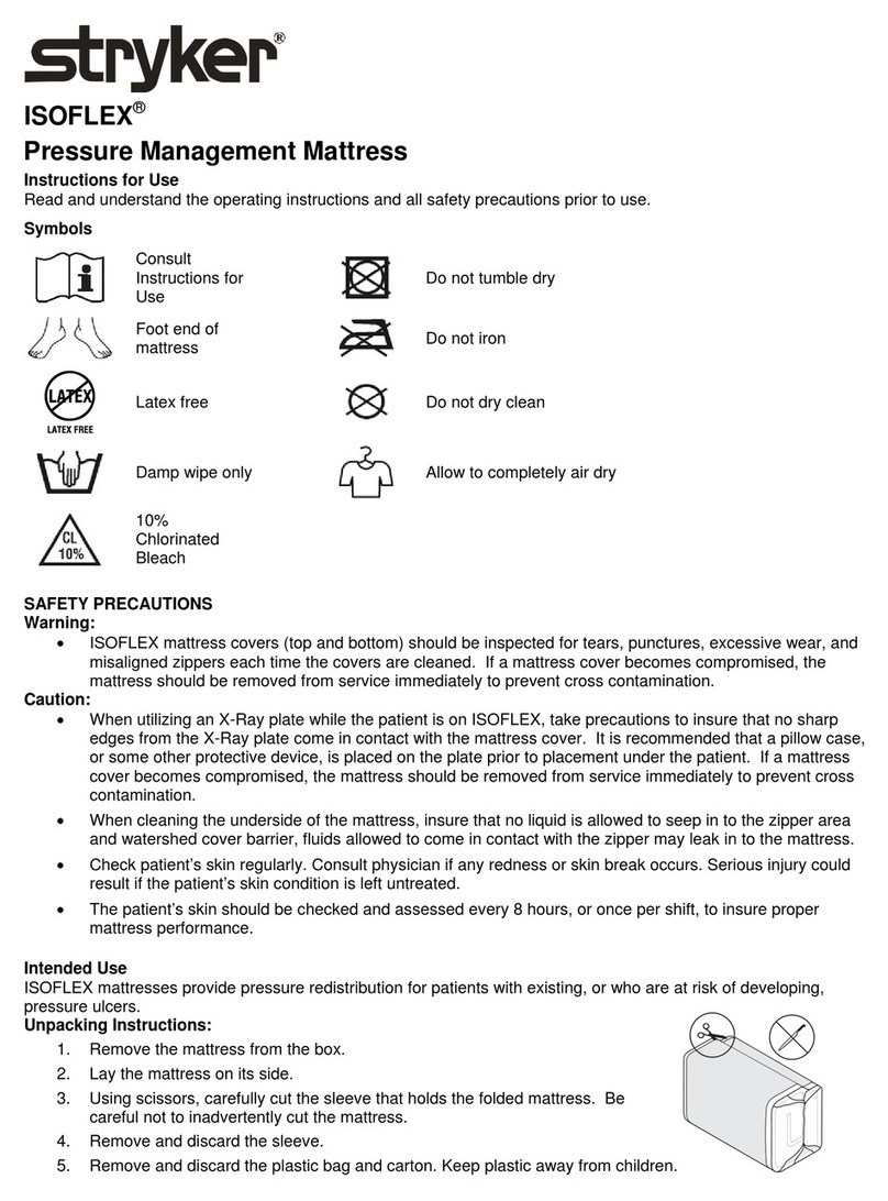
SSyymmbboollss
Operating instructions/Consult instructions for use
General warning
Caution
No pushing
Do not store the oxygen bottle
Catalogue number

Serial number
 
For US Patents see www.stryker.com/patents
CE mark
Authorized representative in the European Community
European medical device
Manufacturer
Safe working load
Lubricate
Type B applied part
1080-009-002 Rev A.0 EN
TTaabbllee ooff CCoonntteennttss
Warning/Caution/Note Definition ..............................................................................................................................3
Summary of safety precautions ................................................................................................................................3
Introduction ...............................................................................................................................................................4
Product description .................................................................................................................................................4
Indications for use...................................................................................................................................................4
Expected service life ...............................................................................................................................................4
Disposal/recycle .....................................................................................................................................................4
Contraindications....................................................................................................................................................5
Specifications .........................................................................................................................................................5
Product illustration ..................................................................................................................................................6
Contact information.................................................................................................................................................6
Serial number location.............................................................................................................................................7
Date of manufacture................................................................................................................................................7
Preventive maintenance ...........................................................................................................................................8
Service ......................................................................................................................................................................9
Caster maintenance ................................................................................................................................................9
Brake cam replacement...........................................................................................................................................9
Brake ring replacement .........................................................................................................................................10
Brake/steer pedal replacement ..............................................................................................................................11
Brake adjustment..................................................................................................................................................11
Jack replacement..................................................................................................................................................12
Siderail latch adjustment........................................................................................................................................14
Remove excess air from the hydraulic system .........................................................................................................15
Pneumatic Fowler adjustment................................................................................................................................15
Prime the pump ....................................................................................................................................................15
Check hydraulic fluid level .....................................................................................................................................16
Base lubrication ....................................................................................................................................................16
Troubleshooting....................................................................................................................................................17
“C” base assembly..................................................................................................................................................18
Jack/control assembly ............................................................................................................................................26
Jack base assembly ...............................................................................................................................................27
Caster wheel assembly...........................................................................................................................................28
Steer caster wheel assembly..................................................................................................................................29
5.75 in. molded wheel assembly ............................................................................................................................30
Brake adjuster assembly ........................................................................................................................................31
Litter assembly........................................................................................................................................................32
Litter assembly, high height option .........................................................................................................................36
Pneumatic Fowler assembly...................................................................................................................................38
Outer housing assembly, right - 1210-031-106 ......................................................................................................39
Outer housing assembly, left - 1210-031-107 ........................................................................................................40
Siderail assembly to litter........................................................................................................................................41
Siderail assembly....................................................................................................................................................43
Accessory rail to litter assembly .............................................................................................................................44
Footboard/chart holder ...........................................................................................................................................46
IV pole, removable - 0390-025-000 ........................................................................................................................47
IV pole assembly, permanent .................................................................................................................................48
Two-stage IV pole assembly - 1211-210-010.........................................................................................................49
IV pole latch - 1211-210-026 ..................................................................................................................................50
Footboard/chart holder - 0785-045-500 .................................................................................................................51
1080-009-002 Rev A.0 1 EN
Upright oxygen bottle holder assembly - 1020-130-000 ........................................................................................52
Ankle restraint strap - 0946-043-001 ......................................................................................................................53
Wrist restraint strap - 0946-044-000.......................................................................................................................54
Body restraint strap - 0390-019-000.......................................................................................................................55
Chest restraint strap - 1010-058-000......................................................................................................................56
Full restraint strap package - 1010-077-000 ..........................................................................................................57
EN 2 1080-009-002 Rev A.0
WWaarrnniinngg//CCaauuttiioonn//NNoottee DDeeffiinniittiioonn
The words WWAARRNNIINNGG,CCAAUUTTIIOONN, and NNOOTTEE carry special meanings and should be carefully reviewed.
WWAARRNNIINNGG
Alerts the reader about a situation which, if not avoided, could result in death or serious injury. It may also describe
potential serious adverse reactions and safety hazards.
CCAAUUTTIIOONN
Alerts the reader of a potentially hazardous situation which, if not avoided, may result in minor or moderate injury to the
user or patient or damage to the product or other property. This includes special care necessary for the safe and effective
use of the device and the care necessary to avoid damage to a device that may occur as a result of use or misuse.
NNoottee -- Provides special information to make maintenance easier or important instructions clearer.
SSuummmmaarryy ooff ssaaffeettyy pprreeccaauuttiioonnss
Always read and strictly follow the warnings and cautions listed on this page. Service only by qualified personnel.
WWAARRNNIINNGG
• Always use caution when you remove the spring to avoid personal injury. The spring is tightly compressed.
• Always follow this procedure if the siderail latches must be adjusted. The siderail latches are preset at the factory and do
not need adjustment. If adjustment is not done properly, injury to the patient or operator could result.
CCAAUUTTIIOONN
• Improper usage of the product can cause injury to the patient or operator. Operate the product only as described in this
manual.
• Do not modify the product or any components of the product. Modifying the product can cause unpredictable operation
resulting in injury to patient or operator. Modifying the product also voids its warranty.
1080-009-002 Rev A.0 3 EN
IInnttrroodduuccttiioonn
This manual assists you with the operation or maintenance of your Stryker product. Read this manual before operating or
maintaining this product. Set methods and procedures to educate and train your staff on the safe operation or maintenance
of this product.
CCAAUUTTIIOONN
• Improper usage of the product can cause injury to the patient or operator. Operate the product only as described in this
manual.
• Do not modify the product or any components of the product. Modifying the product can cause unpredictable operation
resulting in injury to patient or operator. Modifying the product also voids its warranty.
NNoottee
• This manual is a permanent part of the product and should remain with the product even if the product is sold.
• Stryker continually seeks advancements in product design and quality. This manual contains the most current product
information available at the time of printing. There may be minor discrepancies between your product and this manual. If
you have any questions, contact Stryker Customer Service or Technical Support at 1-800-327-0770.
PPrroodduucctt ddeessccrriippttiioonn
The Stryker Model 1080 Fluoroscopy Stretcher is a wheeled stretcher that consists of a platform mounted on a wheeled
frame to transport patients in a horizontal position within a healthcare facility by health professionals or trained
representatives of the user facility. The device has a U-shaped base and full-length C-arm access to enhance imaging
capabilities. The device has siderails, supports for fluid infusion equipment, and various options and accessories that assist
with the support and position of the patient during imaging or procedures requiring fluoroscopic X-ray system and transport
of the patient.
IInnddiiccaattiioonnss ffoorr uussee
The Stryker Model 1080 Fluoroscopy Stretcher is a wheeled device that provides support and positioning of a patient during
transport, imaging, or interventional procedures, especially those requiring the use of a general-purpose fluoroscopic X-ray
system, within healthcare facilities. The device has full-length C-arm access that offers flexibility during imaging and a dual
pneumatic backrest that helps to provide access for imaging without the need to reposition the patient. The stretcher may
be used for minor procedures and short-term stay, typical of existing stretcher applications, including outpatient clinical
evaluation, treatment, minor procedures, and outpatient recovery.
The Fluoroscopy Stretcher is for use in all acute care hospitals and medical outpatient services.
The Fluoroscopy Stretcher has a safe working load up to 500 lb (227 kg).
The Fluoroscopy Stretcher is not for long-term inpatient treatment and recovery.
EExxppeecctteedd sseerrvviiccee lliiffee
The Fluoroscopy Stretcher has a 10 year expected service life under normal use conditions and with appropriate periodic
maintenance.
DDiissppoossaall//rreeccyyccllee
Always follow the current local recommendations and/or regulations governing environmental protection and the risks
associated with recycling or disposing of the equipment at the end of its useful life.
EN 4 1080-009-002 Rev A.0
CCoonnttrraaiinnddiiccaattiioonnss
None known.
SSppeecciiffiiccaattiioonnss
NNoottee -- Safe working load
indicates the sum of the
patient, mattress, and
accessory weight.
500 lb 225 kg
Overall length 87 in. 220.9 cm
Height High 32.75 in. 83.2 cm
Low 23.5 in. 59.7 cm
Overall width 30.5 in. 77.4 cm
Litter positioning Dual backrest operation 0° to 90°
Trendelenburg/Reverse
Trendelenburg
±8°
Patient surface 26 in. x 84 in. 66 cm x 213.4 cm
Siderails 26 in. x 84 in. 33 cm x 139.5 cm
Fluoroscopy window 27.5 in. x 66 in. 69.9 cm x 167.6 cm
Caster diameter 6 in. 15 cm
C-arm access width 54 in. 137.2 cm
Stryker reserves the right to change specifications without notice.
EEnnvviirroonnmmeennttaall ccoonnddiittiioonnss OOppeerraattiioonn SSttoorraaggee aanndd ttrraannssppoorrttaattiioonn
Temperature
100 °F
(38 °C)
50 °F
(10 °C)
140 °F
(60 °C)
-4 °F
(-20 °C)
Relative humidity
75%
30%
95%
10%
Atmospheric pressure
1060 hPa
700 hPa
1060 hPa
500 hPa
1080-009-002 Rev A.0 5 EN
PPrroodduucctt iilllluussttrraattiioonn
H
J
A
B
C
D
E
F
G
K
K
ABrake/steer pedal FIV pole
BBumper G Pneumatic backrest
C Caster H Pneumatic backrest release handle
DFoot end hydraulic release pedal JPump pedal
EHead end hydraulic release pedal K Siderail
CCoonnttaacctt iinnffoorrmmaattiioonn
Contact Stryker Customer Service or Technical Support at: 1-800-327-0770.
Stryker Medical
3800 E. Centre Avenue
Portage, MI 49002
USA
NNoottee -- The user and/or the patient should report any serious product-related incident to both the manufacturer and the
Competent authority of the European Member State where the user and/or patient is established.
To view your operations or maintenance manual online, see https://techweb.stryker.com/.
Have the serial number (A) of your Stryker product available when calling Stryker Customer Service or Technical Support.
Include the serial number in all written communication.
EN 6 1080-009-002 Rev A.0
SSeerriiaall nnuummbbeerr llooccaattiioonn
A
DDaattee ooff mmaannuuffaaccttuurree
The year of manufacture is the first four digits of the serial number.
1080-009-002 Rev A.0 7 EN
PPrreevveennttiivvee mmaaiinntteennaannccee
Remove product from service before you perform the preventive maintenance inspection. Check all items listed during
annual preventive maintenance for all Stryker Medical products. You may need to perform preventive maintenance checks
more often based on your level of product usage. Service only by qualified personnel.
Clean and disinfect the exterior of the mattress before inspection, if applicable.
Inspect the following items:
All welds
All fasteners are secure
Brake mechanism works
Steer function works
Siderails raise, lower, and latch
Casters lock when you apply the brakes
Casters secure and swivel
Casters are free of wax or debris
Fowler backrest raises, lowers, and latches
Skins are not cracked
Trendelenburg/Reverse Trendelenburg raises and lowers from all locations
IV pole is intact (optional)
Oxygen bottle holder is intact and is in good working condition (optional)
Body restraints are not torn and can be adjusted and latched
Accessories and mounting hardware are in good working condition
No rips, tears, or cracks in the mattress cover
VVeellccrroo® on the mattress is in good condition
VVeellccrroo® on litter is in good condition; replace if necessary (0381-024-007)
Ground chain is intact
No leaks at hydraulic connections
Hydraulic jacks holding
Hydraulic drop rate is set
Hydraulic oil level is sufficient
Lubricate where required, including the brake adjuster assembly, brake cam, and pump bar pivot brackets
Product serial number:
Completed by:
Date:
EN 8 1080-009-002 Rev A.0
SSeerrvviiccee
CCaasstteerr mmaaiinntteennaannccee
TToooollss rreeqquuiirreedd::
• 5/8” combination wrench
• 11/16” combination wrench
PPrroocceedduurree::
1. Apply the brakes. Push on the product to make sure that the brakes are working.
2. Using a 5/8” combination wrench and a 11/16” combination wrench, remove the lock nut (A) from the bolt (B) (Figure 1).
3. Support the corner of the product where the caster is being removed.
4. Remove the bolt (B) and the molded wheel (C).
5. Clean the bolt, molded wheel, and the inside of the caster horn (D) to remove any dirt and debris.
FFiigguurree 11 –– CCaasstteerr mmaaiinntteennaannccee
6. Make sure that the bearings in the molded wheel spin with ease.
7. Reverse steps to reinstall.
8. Verify proper operation before you return the product to service.
BBrraakkee ccaamm rreeppllaacceemmeenntt
TToooollss rreeqquuiirreedd::
• 1/8” hex wrench
• 3/32” hex wrench
• Bungee cords
1080-009-002 Rev A.0 9 EN
PPrroocceedduurree::
1. Raise the base hood and support the base hood with bungee cords.
2. Using a 3/32” hex wrench, loosen the set screw that holds the brake adjuster to the brake ring. Turn the adjuster
clockwise to remove it.
3. Using a 1/8” hex wrench, remove the shoulder bolt and nut that hold the brake link on the cam. Remove the cam.
4. Revers steps to install the supplied cam.
5. Verify proper operation before you return the product to service.
BBrraakkee rriinngg rreeppllaacceemmeenntt
TToooollss rreeqquuiirreedd::
• 3/4” wrench
• 3/4” socket
• 3/4” ratchet
• 3/32” hex wrench
• Small floor jack
• Needle nose pliers
• Bungee cords
PPrroocceedduurree::
1. Put the brake/steer pedal in the neutral position.
2. Raise the litter to the highest position.
3. Raise the base hood and support the base hood with bungee cords.
4. Using a small floor jack, lift the end of the product until the casters are approximately 12” off the floor.
5. Using a 3/32” hex wrench, loosen the set screw that holds the brake adjuster to the brake ring.
6. Turn the brake adjuster clockwise to remove it.
7. Remove both of the casters on the end of the product being serviced.
8. Using a 3/4” socket and a 3/4” ratchet, on the inside of the caster horn and a 3/4” wrench on the caster nut, remove the
bolt and caster horn (
Caster maintenance
(page 9)).
9. Using needle nose pliers, squeeze the spring between the brake cam and the brake ring and remove the spring.
WWAARRNNIINNGG -- Always use caution when you remove the spring to avoid personal injury. The spring is tightly compressed.
10.Remove the spring from the pump pedal.
11.Lower and remove the brake ring from the base.
12.Remove the brake pads and bushings.
13.Install the brake pads and bushings on the supplied brake ring.
14.Reverse steps to install the supplied brake ring.
15.Apply and release the brakes to make sure that the brakes are working.
16.If adjustment is needed, see
Brake adjustment
(page 11).
NNoottee -- Make sure that the set screw hole in the brake ring collar is facing toward the inside of the base when you install
the brake ring.
17.Verify proper operation before you return the product to service.
EN 10 1080-009-002 Rev A.0
BBrraakkee//sstteeeerr ppeeddaall rreeppllaacceemmeenntt
TToooollss rreeqquuiirreedd::
• (2) 7/16” wrenches
• 3/16” drive pin
• 3/8” box end wrench
• Hammer
• Bungee cords
•LLooccttiittee® 409 or equivalent
PPrroocceedduurree::
NNoottee -- Two people are required to safely perform this procedure.
1. Raise the base hood and support the base hood with bungee cords.
2. Put the brake/steer pedal in the brake position. If you cannot apply the brake, with assistance from another person, use
a large wrench or pry tool to push down on the brake bar (compressing the spring). Manually move the molded plastic
brake cam to the brake position at both ends of the base.
3. Raise the litter to the highest position.
4. Raise the Fowler backrest.
5. Raise the siderails to the full up position.
6. Using a 3/8” box end wrench, remove the bolt in the litter support tube above the black bellows on both ends.
7. With the assistance of another person, lift the litter off of the litter support tube and set the litter aside.
8. Remove the base hood.
9. Using (2) 7/16” wrenches, remove the bolt, nut and washers that hold the square brake drive link assembly on the brake
actuator on both sides of the base.
10.While lifting one end (head end or foot end) of the base, rotate the brake/steer pedal so that the bottom of the pedal is
facing up.
11.Working from the bottom of the brake/steer pedal, use a hammer and a 3/16” drive pin to remove the groove pin from
the brake/steer pedal.
12.Remove the brake/steer pedal from the brake rod (use hammer, if necessary).
13.Rotate the brake rod so that the actuators are upright.
14.Install the supplied brake/steer pedal on the brake rod. Align the holes in the brake/steer pedal with the holes in the
brake rod.
15.Apply LLooccttiittee® 409 or equivalent to the supplied groove pin.
16.From the top of the brake/steer pedal, use a hammer to install the supplied groove pin. Use the drive pin, if necessary, to
make sure that the groove pin is flush with the top of the brake/steer pedal.
17.Install the brake drive link assemblies on the brake actuator on both sides of the base.
18.Apply and release the brake to make sure that the brake is working.
19.Lower the base hood.
20.With the assistance of another person, lift the litter and position it on the litter support tube.
21.Using a 3/8” box end wrench, install the bolt in the litter support tube above the black bellows on both ends.
22.Verify proper operation before you return the product to service.
BBrraakkee aaddjjuussttmmeenntt
TToooollss rreeqquuiirreedd::
1080-009-002 Rev A.0 11 EN
• 3/32” hex wrench
• Pry bar
PPrroocceedduurree::
NNoottee -- The flat on the thread of the stud must always be aligned with the set screw. The turn must be a full circle only.
1. Using a pry bar (A), compress the spring to relieve tension on the stud (Figure 2).
2. Using a 3/32” hex wrench, turn the set screw (B) one full turn counterclockwise to tighten the brake.
3. Using a 3/32” hex wrench, turn the set screw (B) one full turn clockwise to loosen the brake.
4. Verify proper operation before you return the product to service.
B
FFiigguurree 22 –– BBrraakkee aaddjjuussttmmeenntt
JJaacckk rreeppllaacceemmeenntt
TToooollss rreeqquuiirreedd::
• 7/16” wrench
• 7/16” socket
• 6” extension with ratchet
• 5/32” hex wrench
• 3/8” box end wrench
• (2) 1/2” wrench
• 3/16” hex wrench
• Spring compression tool
PPrroocceedduurree::
NNoottee -- Two people are required to safely perform this procedure.
1. Apply the brake. Push on the product to make sure that the brake is working.
EN 12 1080-009-002 Rev A.0
2. Raise the litter to the highest position.
3. Raise the Fowler backrest.
4. Using a 3/8” box end wrench, remove the square head set screws from both the head end and the foot end jack support
tubes. With the assistance of another person, lift the litter top off of the jack support tubes and set it aside.
5. Remove the base hood.
6. Using a 1/2” wrench, remove the screw (A), external tooth lock washers (B), and Nylock nuts (C) that hold the pump link
roller bar assembly (D), (E), and (F) to the base (see Figure 3).
A
C
D
E
F
Y
AA
AB
AC
AD/
AH
E
B
B
B
B
C
C
CF
AE
L
Y
ABAA
A
FFiigguurree 33 –– JJaacckk rreeppllaacceemmeenntt
7. Using a 1/2” wrench and a 3/16” hex wrench, remove the shoulder screws (H), washers (J), and Nylock nuts (K) that
hold the link (R) to the pump bar weldment (L) (see Figure 4).
1080-009-002 Rev A.0 13 EN
HK
L
M
N
P
R
T
U
V
W
J
AF
AG
FFiigguurree 44 –– AAsssseemmbbllyy jjaacckk oonn bbaassee
8. Using the spring compression tool, compress the spring (V).
9. Using a 1/2” wrench, remove the Nylock nut (M) and the washer (N) from the base stud and remove the horizontal pump
link (P) and the swing pump link (R).
10.With the spring compression tool still in place, remove the pump link weldment (T).
11.Remove the spring tool.
NNoottee -- Use extreme caution when removing the spring compression tool. The spring and top spring guide are still under
pressure and could cause personal injury if they are allowed to break free.
12.Remove the spring guide (U), the spring (V), the spring holder guide (W), and the jack washer from the jack pump.
13.Using (2) 1/2” wrenches, remove the screws (Y), lock washers (AA) and Nylock nuts (AB) holding the jack support
bracket (AC) to the frame. When reinstalling, do not overtighten the screws to avoid damage to the jack reservoir tube.
14.Using a 3/8” box end wrench and a 5/32” hex wrench, remove the screws (AD) and the Nylock nuts (AE) holding the jack
manifold to the base.
15.Using a 7/16” wrench, a 7/16” socket, and a 6” extension with ratchet, remove the screws (AF), washers (AG), and
Nylock nuts (AH) holding the jack assembly to the base.
16.Reverse steps to reinstall.
17.Verify proper operation before you return the product to service.
SSiiddeerraaiill llaattcchh aaddjjuussttmmeenntt
WWAARRNNIINNGG -- Always follow this procedure if the siderail latches must be adjusted. The siderail latches are preset at the
factory and do not need adjustment. If adjustment is not done properly, injury to the patient or operator could result.
TToooollss rreeqquuiirreedd::
• 1/8” hex wrench
EN 14 1080-009-002 Rev A.0
PPrroocceedduurree::
1. Using a 1/8” hex wrench, adjust the hex screw located on the latch assembly opposite the latch.
2. Turn the screw:
a. Clockwise to decrease the amount of play in the latching mechanism
b. Counterclockwise to increase the amount of play in the latching mechanism
NNoottee -- The amount of play in the siderail, when in the full up and latched position, should be approximately 1/8” to 3/
16”.
• Too much play, when the siderail is in the full up and latched position, will give the siderail the appearance of
being unstable and could also cause premature wearing of the latch system.
• Too little play, when the siderail is in the full up and latched position, will obstruct the latch and the latch will not
latch in place, which may result in damage to the latch or injury to the patient or operator.
3. Verify proper operation before you return the product to service.
RReemmoovvee eexxcceessss aaiirr ffrroomm tthhee hhyyddrraauulliicc ssyysstteemm
TToooollss rreeqquuiirreedd::
• None
PPrroocceedduurree::
1. Raise the product to the highest position.
2. Push down on the pump pedal several times to force the air through the system.
3. Verify proper operation before you return the product to service.
PPnneeuummaattiicc FFoowwlleerr aaddjjuussttmmeenntt
TToooollss rreeqquuiirreedd::
• 5/32” hex wrench
• 1/2” combination wrench
PPrroocceedduurree::
1. Raise the Fowler to 75 degrees or higher.
2. Using a 1/2” combination wrench, loosen the hex nuts in the actuator arms on the end of the trip bar.
3. To adjust the Fowler, use a 5/32” hex wrench to turn the hex screws:
a. Counterclockwise 1 to 2 turns if the Fowler will not move
b. Clockwise 1 to 2 turns if the Fowler will not hold its position
4. Using a 1/2” combination wrench, tighten the hex nuts. Make sure that the Fowler travels from flat to 90 degrees and
down again and that the Fowler holds its position when weight is applied.
5. Verify proper operation before you return the product to service.
PPrriimmee tthhee ppuummpp
TToooollss rreeqquuiirreedd::
• None
PPrroocceedduurree::
1. Remove the pump link and the spring (see
Jack replacement
(page 12)).
1080-009-002 Rev A.0 15 EN
2. Push on the pump by hand and make sure the pump piston bottoms to remove air.
3. Reassemble the pump link and spring.
4. Check for leaks.
5. Verify proper operation before you return the product to service.
CChheecckk hhyyddrraauulliicc fflluuiidd lleevveell
TToooollss rreeqquuiirreedd::
•MMoobbiillee HFA hydraulic fluid (2020-070-475)
PPrroocceedduurree::
1. Lower the litter to the lowest position.
2. Remove the fill plug on the side of the jack.
3. Add MMoobbiillee HFA hydraulic fluid until the fluid is visible at the bottom of the fill hole, if necessary.
NNoottee -- Do not use other types of oil. Damage to the hydraulic units may occur.
4. Reinstall the fill plug.
BBaassee lluubbrriiccaattiioonn
TToooollss rreeqquuiirreedd::
• MPG-2 grease
PPrroocceedduurree::
1. Using MPG-2 or equivalent grease, lubricate the brake adjuster rod around the areas noted at (A) (Figure 5)
NNoottee -- Do not grease these areas (B) (Figure 5).
2. Remove retaining plates (C).
AB
C
FFiigguurree 55 –– BBaassee lluubbrriiccaattiioonn
3. Raise the pump bar weldment.
4. Grease the pump bar pivot brackets.
5. Grease the retaining plates where they come in contact with the pump bar before you reinstall the retaining plates.
EN 16 1080-009-002 Rev A.0

Other manuals for 1080

4

Other Stryker Medical Equipment manuals

Stryker Core 5400-050-000 User manual

Stryker

Stryker Core 5400-050-000 User manual

Stryker 240-099-109 Operating instructions

Stryker

Stryker 240-099-109 Operating instructions

Stryker Renaissance 1210 User manual

Stryker

Stryker Renaissance 1210 User manual

Stryker Secure 3000 User manual

Stryker

Stryker Secure 3000 User manual

Stryker 6390 User manual

Stryker

Stryker 6390 User manual

Stryker 1069 User manual

Stryker

Stryker 1069 User manual

Stryker Secure Connect Manual

Stryker

Stryker Secure Connect Manual

Stryker 240-099-155 User manual

Stryker

Stryker 240-099-155 User manual

Stryker 1079 User manual

Stryker

Stryker 1079 User manual

Stryker nGenius Universal Tracker User manual

Stryker

Stryker nGenius Universal Tracker User manual

Stryker Trio 1033 User manual

Stryker

Stryker Trio 1033 User manual

Stryker Gynnie 1061 User manual

Stryker

Stryker Gynnie 1061 User manual

Stryker LIFEPAK 20 Installation instructions

Stryker

Stryker LIFEPAK 20 Installation instructions

Stryker SECUR-FIT ADVANCED User manual

Stryker

Stryker SECUR-FIT ADVANCED User manual

Stryker FL23SE User manual

Stryker

Stryker FL23SE User manual

Stryker Performance-LOAD Cot Fastener System User manual

Stryker

Stryker Performance-LOAD Cot Fastener System User manual

Stryker 1000 User manual

Stryker

Stryker 1000 User manual

Stryker SDC Ultra User manual

Stryker

Stryker SDC Ultra User manual

Stryker MV3 5900 User manual

Stryker

Stryker MV3 5900 User manual

Stryker Speed-Sheet 6010 User manual

Stryker

Stryker Speed-Sheet 6010 User manual

Stryker CUB FL19H User manual

Stryker

Stryker CUB FL19H User manual

Stryker IsoAir 2941 User manual

Stryker

Stryker IsoAir 2941 User manual

Stryker FL25E User manual

Stryker

Stryker FL25E User manual

Stryker 1115 User manual

Stryker

Stryker 1115 User manual

Popular Medical Equipment manuals by other brands

acumed SLIC manual

acumed

acumed SLIC manual

Dräger Julian operating instructions

Dräger

Dräger Julian operating instructions

Direct Healthcare Services Dyna-Form Mercury Safety 7 user manual

Direct Healthcare Services

Direct Healthcare Services Dyna-Form Mercury Safety 7 user manual

Avanos CORTRAK 2 Quick reference guide

Avanos

Avanos CORTRAK 2 Quick reference guide

MedRx Avant A2D+ installation manual

MedRx

MedRx Avant A2D+ installation manual

Leica M530 OHX user manual

Leica

Leica M530 OHX user manual

SonoSite PowerPack user guide

SonoSite

SonoSite PowerPack user guide

Act Fast Anti Choking Trainer user manual

Act Fast

Act Fast Anti Choking Trainer user manual

BeaconMedaes Gemini Service manual

BeaconMedaes

BeaconMedaes Gemini Service manual

COOK Medical EchoTip ProCore Instructions for use

COOK Medical

COOK Medical EchoTip ProCore Instructions for use

Viatom Wellue POD-2 user manual

Viatom

Viatom Wellue POD-2 user manual

Otto Bock 50K13 Genu Arexa Instructions for use

Otto Bock

Otto Bock 50K13 Genu Arexa Instructions for use

EDAN SE-601A user manual

EDAN

EDAN SE-601A user manual

Acrel AIM-M300 Installation and operation manual

Acrel

Acrel AIM-M300 Installation and operation manual

Chattanooga 70002 installation instructions

Chattanooga

Chattanooga 70002 installation instructions

Power Plate Pro5M Instructions for use

Power Plate

Power Plate Pro5M Instructions for use

Menicon ShellPa Pro instruction manual

Menicon

Menicon ShellPa Pro instruction manual

ConMed Sabre Genesis Service manual

ConMed

ConMed Sabre Genesis Service manual

manuals.online logo
manuals.online logoBrands
  • About & Mission
  • Contact us
  • Privacy Policy
  • Terms and Conditions

Copyright 2025 Manuals.Online. All Rights Reserved.