Technical specifications
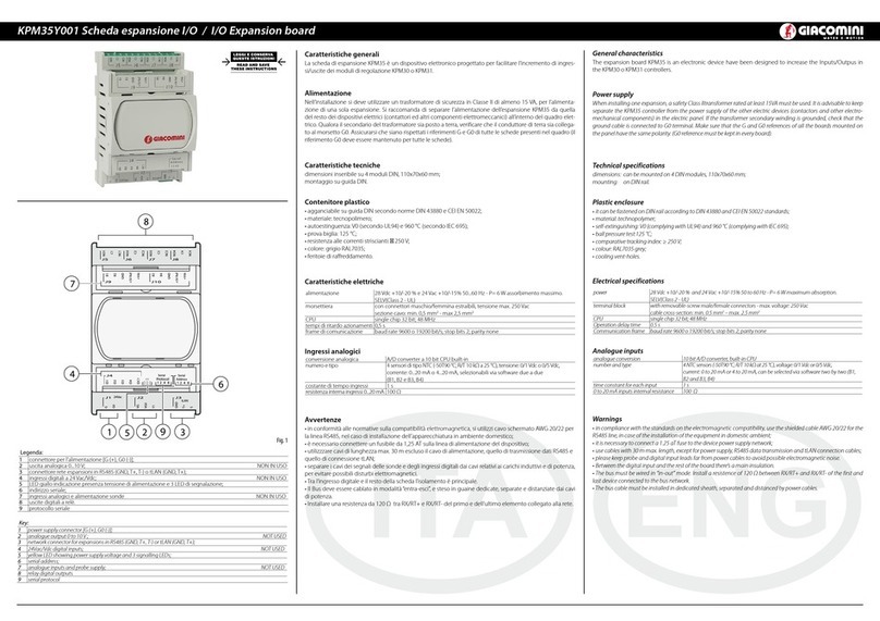
Power supply 12 to 33 V from control board
Power input: 300 mW
BUS power supply 21 to 32V Current input: 5 mA
BUS TP1 9600 baud
Screw terminals Wire cross-section min. 0.2 mm max. 1.5 mm2
YCYM 1 x 2 x 0.8 mm2
Insulation TP bus optically isolated from the earth of the controller (functional insulation)
Index of protection IP00
Operating conditions -20T60 °C, humidity <85% RH non-condensing
Storage conditions -20T80 °C, humidity <85% RH non-condensing
Degree of pollution 2
Cat. of resistance to heat and re Same as the KPM30/KPM31
PTI of the insulating materials PTI≥250
Software class and structure A
Period of electrical stress across the
insulating parts Long
Protection against electric shock
The device only guarantees a functional insulation between the power supply
to the controller and the serial BUS, therefore the controller that the card is
installed on must be supplied by a SELV source
To guarantee the correct operation of the card, avoid fitting KPM30/31 devices with built-in displays in electrical panels
with metal front panels. For further information and technical support relevant to the product, please contact the email
Disposal: The appliance (or the product) must be disposed of separately in compliance with the local standards in
force on waste disposal.
WARNINGS
Precautions when handling the card.
Electrical damage that occurs to electronic components is almost always the result of electrostatic discharges from the operator.
Suitable precautions must be therefore be taken when handling these components, specifi cally:
• before handling any electronic component or board, touch an earthed object (not touching a component is not suffi cient, as
static electricity can produce a 10000 V spike discharge which can form an arc of about 1 cm);
• all materials must be kept inside their original package as long as possible. If necessary, take the card from its packaging and place
it into an antistatic package without touching the side of the card where the electronic components are fitted;
• absolutely avoid non-antistatic plastic bags, polystyrene or sponges; do not pass the card directly between operators (to prevent
from electrostatic induction and discharges).
Note: All registered trademarks are the property of their respective owners.
Scheda Konnex per modulo di regolazione KPM30/KPM31
Konnex board for KPM30/KPM31 regulation unit
KPM36Y002
Fig. 4
Fig. 5
LED Signicato Errore/Rimedi
Rosso
Acceso sso
Errore assenza comunicazione
modbus tra scheda KNX e
KPM30/31
Congurazione:
- Indirizzo KPM30/31 errato
- Baudrate KPM30/31 non corretto
- protocollo KPM30/31 errato
Lampeggiante Errore comunicazione modbus tra
scheda KNX e KPM30/31
Modbus exception:
- la scheda è stata congurata con indirizzi
modbus errati o non supportati
Verde
Acceso sso
È stato premuto il tasto per
l’assegnazione dell’indirizzo e la
scheda è in attesa che da ETS3,
ETS4 si proceda con la relativa
procedura
Lampeggiante veloce
- Non è stata caricata la tabella
cioè il le .XML
- Un lampeggio veloce breve
indica la ricezione dell’indirizzo
dopo la pressione del tasto
Scaricare la tabella XML da ETS
Lampeggiante lento
Congurazione in corso:
ETS3, ETS4 stà eettuando il
download del le XML
Verde
+
Rosso
Accesi entrambi ssi Mancanza alimentazione Bus
Konnex
Vericare: alimentatore bus Konnex, colle-
gamenti elettrici e polarità connessioni ai
morsetti + e - del connettore.
LED Meaning Error/Solution
Red
On steady No Modbus communication
between KNX card and KPM30/31
Con guration :
- KPM30/31 address incorrect
- KPM30/31 baud rate not correct
- KPM30/31 wrong protocol
Flashing Modbus communication error
between KNX card and KPM30/31
Modbus exception:
- the card has been congured with a wrong
Modbus or unsupported addresses
Green
On steady
The button has been pressed for the
assignment of the address and the
card is awaiting the corresponding
procedure from ETS3, ETS4
Flashing fast
- The table has not been loaded,
that is, the .XML le
- One short fast ash indicates the
reception of the address after
pressing the button
Download the XML table from ETS
Flashing slow Con guration in progress: ETS3,
ETS4 is downloading the XML le
Green
+
Red
Both on steady No power supply to Konnex Bus
Check: Konnex bus power supply, electrical
connections and polarity of the connections
to terminals + and – on the connector.
Caratteristiche Tecniche
Alimentazione 12÷33 V da scheda controllo
Potenza assorbita: 300 mW
Alimentazione BUS 21÷32 V Corrente assorbita: 5 mA
BUS TP1 9600 baud
Morsetti a vite Sezione conduttori min. 0,2 mm max. 1,5 mm2
YCYM 1 x 2 x 0,8 mm2
Isolamento Bus TP Optoisolato dalla massa del controllo (isolamento funzionale)
Grado di protezione IP00
Condizioni di funzionamento -20T60 °C, umidità <85% U.R. non condensante
Condizioni di immagazzinamento -20T80 °C, umidità <85% U.R. non condensante
Grado di inquinamento 2
Cat. di resistenza al calore e al fuoco Stesso della KPM30/KPM31
PTI dei materiali di isolamento PTI≥250
Classe e struttura del software A
Periodo delle sollecitazioni elettriche
delle parti isolanti Lungo
Protezione contro le scosse elettriche
Il dispositivo garantisce solo un isolamento funzionale tra la sorgente di alimen-
tazione del controllo e il BUS seriale, pertanto il controllo su cui viene installata la
scheda deve essere alimentato da sorgente SELV
Al fine di garantire il corretto funzionamento della scheda evitare di montare i dispositivi KPM30/31 con display built-in in
quadri elettrici con frontale metallico. Per informazioni e supporto tecnico relativo al prodotto contattare l’indirizzo email
Sfilamento: l’apparecchiatura (o il prodotto) deve essere oggetto di raccolta separata in conformità alle vigenti normative
locali in materia di smaltimento.
AVVERTENZE
Precauzioni nel maneggiare la scheda.
I danneggiamenti elettrici che si verifi cano sui componenti elettronici avvengono quasi sempre a causa delle scariche elettrostatiche
indotte dall’operatore. È quindi necessario prendere adeguati accorgimenti per queste categorie di componenti, ed in particolare:
• prima di maneggiare qualsiasi componente elettronico o scheda, toccare una messa a terra (il fatto stesso di evitare di toccare un
componente non è sufficiente in quanto una scarica di 10000 V, tensione molto facile da raggiungere con l’elettricità statica, innesca
un arco di circa 1 cm);
• i materiali devono rimanere per quanto possibile all’interno delle loro confezioni originali. Se necessario, prelevare la scheda da una
confezione e trasferire il prodotto in un imballo antistatico senza toccare con le mani i lati della scheda su cui sono montati i compo-
nenti elettronici;
• evitare nel modo più assoluto di utilizzare sacchetti in plastica, polistirolo o spugne non antistatiche;evitare nel modo più assoluto il
passaggio diretto tra operatori (per evitare fenomeni di induzione elettrostatica e conseguenti scariche).
Nota: Tutti i marchi registrati sono proprietà dei rispettivi titolari.
AVVERTENZE PER IL CORRETTO SMALTIMENTO DEL PRODOTTO
Questoprodottorientranelcampodiapplicazione della Direttiva2012/19/UE
riguardantelagestionedei riuti diapparecchiatureelettriche ed elettroniche
(RAEE). L’apparecchio non deve essere eliminato con gli scarti domestici in
quanto composto da diversi materiali che possono essere riciclati presso
le strutture adeguate. Informarsi attraverso l’autorità comunale per quanto
riguarda l’ubicazione delle piattaforme ecologiche atte a ricevere il prodotto per lo
smaltimento ed il suo successivo corretto riciclaggio. Si ricorda, inoltre, che a fronte di
acquisto di apparecchio equivalente, il distributore è tenuto al ritiro gratuito del prodotto
da smaltire. Il prodotto non è potenzialmente pericoloso per la salute umana e l’ambiente,
ma se abbandonato nell’ambiente impatta negativamente sull’ecosistema. Leggere
attentamenteleistruzioniprimadiutilizzarel’apparecchioper laprima volta.Siraccomanda
di non usare assolutamente il prodotto per un uso diverso da quello a cui è stato destinato,
essendoci pericolo di shock elettrico se usato impropriamente.
Il simbolo del bidone barrato, presente sull’etichetta posta sull’apparecchio, indica la
rispondenza di tale prodotto alla normativa relativa ai riuti di apparecchiature elettriche
edelettroniche.L’abbandononell’ambiente dell’apparecchiaturaolosmaltimento abusivo
della stessa sono puniti dalla legge.
IMPORTANT INFORMATION FOR CORRECT DISPOSAL OF THE PRODUCT
This product falls into the scope of the Directive 2012/19/EU concerning the management of
Waste Electrical and Electronic Equipment (WEEE). This product shall not be dispose in to the
domestic waste as it is made of different materials that have to be recycled at the appropriate
facilities. Inquire through the municipal authority regarding the location of the ecological
platforms to receive the product for disposal and its subsequent correct recycling. Furthermore,
upon purchase of an equivalent appliance, the distributor is obliged to collect the product for
disposal free of charge. The product is not potentially dangerous for human health and the
environment,butifabandonedintheenvironmentcanhavenegativeimpactontheenvironment.
Read carefully the instructions before using the product for the first time. It is recommended
that you do not use the product for any purpose rather than those for which it was intended,
there being a danger of electric shock if used improperly.
Thecrossed-out wheeled dustbinsymbol, on the label on the product,indicates the compliance
of this product with the regulations regarding Waste Electrical and Electronic Equipment.
Abandonment in the environment or illegal disposal of the product is punishable by law.
Additional information. For more information, go to giacomini.com or contact our technical assistance service.
This document provides only general indications. Giacomini S.p.A. may change at any time, without notice and for
technical or commercial reasons, the items included herewith. The information included in this technical sheet do
not exempt the user from strictly complying with the rules and good practice standards in force. 047U54158
12/2018


