manuals.online logo
Brands
  1. Home
  2. •
  3. Brands
  4. •
  5. Giacomini
  6. •
  7. Thermostat
  8. •
  9. Giacomini K495L User manual

Giacomini K495L User manual

1
0680ML Maggio 2014 - May 2014
Termoregolazione - ThermoregulaTion
TermosTaTo ambienTe con sonda di TemperaTura e
umidiTà K495L
Room theRmostat K495L
ISO
14001
0032A/3
OHSAS
18001
0064L/1
ISO
9001
0006/7
• Protezione contro i cortocircuiti: deve essere garantita dal costruttore
dell’apparecchiatura in cui il K495LY002 viene integrato o dall’installatore nale
• Immunità contro sovratensioni: categoria 1
• Sezione dei conduttori: da 0,5 a 1,5 mm2
• Precisione della misura di temperatura: ±2 °C
• Precisione della misura di umidità: ±10 % U.R. (nei modelli dotati di sonda di
umidità opzionale) apparecchiature di classe I e II
• PTI dei materiali Isolanti: 250 V
• Periodo delle sollecitazioni elettriche delle parti isolanti: Lungo
• Grado di inquinamento ambientale: Normale
• Categoria di resistenza al calore ed al fuoco: Categoria D (per scatola e coperchio)
• Categoria di immunita’contro le sovratensioni: Categoria 2
• Power supply (according to EN60730-1): 24 Vac ±15 %, 50/60 Hz 70 mA 1.5 VA or
31 Vdc ± 29 % 70 mA
• Classication according to UL873:
- Power supply input: 24 V ac, 50-60Hz, Class 2 - 25.5 - 36.25 V dc, Class 2
- Power consumption, max 1 watt
- Outputs: serial link RS485, Class 2
• Operating conditions: 0÷50 °C; 10 to 85% rH non-condensing
• Storage conditions: -20÷70 °C; 0 to 85 % rH non-condensing
• Environmental pollution: normal
• Degree of pollution: degree II
• Category of resistance to heat and re: A
• Software class and structure: A
• Index of protection: IP30
• Ball pressure test temperature on the plastic case: 100 °C
• Classication according to protection against electric shock (EN60730-1): III, to be
integrated into class I or II appliances
• Period of electrical stress across the insulating parts: long
• Control device designed to be supplied to: manufacturers, installers and
maintenance personne
• Protection against short-circuits: must be guaranteed by the manufacturer of the
appliance that the K495LY002 is integrated into or by the installer
• Immunity against voltage surges: category 1
• Cross-section of the wires: from 0.5 to 1.5 mm2
• Precision of temperature measurement: ±2 °C
• Precision of humidity measurement: ±10 % rH. (in the models tted with optional
humidity probe)
Installazione - Installation
Togliere l’alimentazione prima di intervenire sul dispositivo in fase di montaggio,
manutenzione e sostituzione. La distanza dei fori di montaggio è studiata per
poter  ssare il dispositivo ad una scatola da incasso conforme alle normative CEI
C.431 - IEC 670. Se questa non è presente, usare i fori di montaggio sul guscio
come guida per la foratura sul muro e utilizzare poi il kit di viti e tasselli in dotazione.
I cavi di collegamento devono passare attraverso il foro presente nel centro del
guscio posteriore del dispositivo, e devono venire  ssati ai morsetti posti sul
guscio stesso (Fig. 1.a). Per accedere ai morsetti di connessione è necessario
sganciare il guscio posteriore facendo leva sull’apposita linguetta. L’apertura e la
chiusura del dispositivo devono avvenire applicando un movimento “a cerniera”
facendo perno sul lato superiore dello strumento e sollevando quello inferiore
(vedi Fig. 1.b). In fase di chiusura fare attenzione che i perni sulla scheda si in lino
nei corrispondenti morsetti, e che i cavi non ostacolino l’operazione.
Disconnect the power supply before working on the K495LY002 during the assembly,
maintenance and replacement operations. The distances between the fastening
holes are designed so as to be able to  t the device to a ush-mounting connection
box compliant with the CEI C.431 - IEC 670 standards. If this is not available, use the
fastening holes on the shell as a guide for drilling holes in the wall, and then use the
kit of screws and plugs supplied. The connection cables must pass through the hole
in the centre of the rear shell of the device, and must be connected to the terminals
located on the shell (Fig. 1.a). To access the connection terminals, remove the rear
shell by levering the tab. The device is opened and closed with a “hinge” movement,
pivoting the top part of the instrument and lifting the bottom part (see Fig. 1.b).
When closing, make sure that the pins on the board  t into the corresponding
terminals, and that the cables do not hinder the procedure.
Descrizione - Description
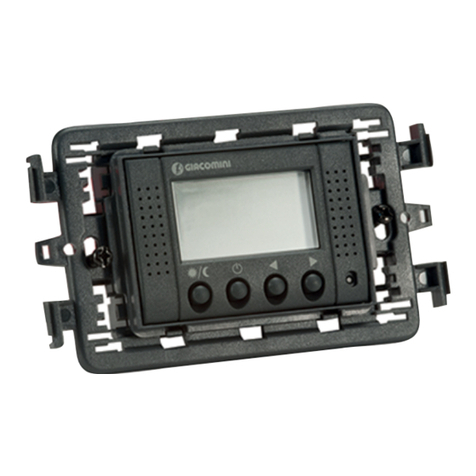
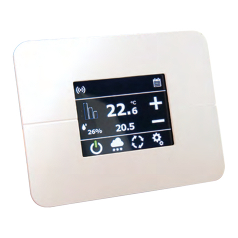
Il termostato ambiente con sonda di temperatura e umidità K495L permetto il
controllo degli impianti di riscaldamento e/o rarescamento in combinazione
con il modulo di regolazione KPM30 o KPM31, al quale è collegato tramite
Bus. Il termostato K495L è stato sviluppato per essere installato a parete su
scatola a 3 posti standard italiano, oppure per essere applicato direttamente a
muro tramite tasselli. Attraverso la connessione Bus il termostato comunica al
modulo di regolazione i valori di temperatura e umidità relativa dell’ambiente
in cui è installato. La visualizzazione e l’impostazione della temperatura
ambiente misurata e desiderata può essere eettuata sia direttamente dal
display del termostato sia centralmente dal display del modulo di regolazione.
The room thermostat with temperature sensor and humidity K495L allow control
of heating and/or air-cooling in combination with the regulation unit KPM30 or
KPM31, to which it is connected by bus. The thermostat K495L was developed to
be installed on the wall of box 3 seater Italian standard, or to be applied directly to
the wall using wall anchors. By the bus connection the thermostat communicates
to the regulation unit the values of temperature and relative humidity of the room
in which it is installed. Viewing and setting the temperature measured and desired
can be done directly from the display of the thermostat or centrally by the display
of the control module.
Versioni e codici - Versions and product codes
Codice
Product code
Alimentazione
Power supply
K495LY002 24 Vac
Dati tecnici - Technical data
• Tensione di alimentazione (secondo EN60730-1): 24 Vac ±15 %, 50/60 Hz 70
mA 1,5 VA oppure 31 Vdc ±29 % 70 mA
• Classicazione secondo UL873:
- Ingresso alimentazione: 24 V ac, 50-60Hz, Class 2 - 25.5 - 36.25 V dc, Class 2
- Power consumption: max 1 watt
- Uscite: serial link RS485, Class 2
• Condizioni di funzionamento: 0÷50 °C; 10...85% U.R. non condensante
• Condizioni di immagazzinamento: -20÷70 °C; 0...85 % U.R. non condensante
• Inquinamento ambientale: normale
• Grado di Inquinamento: grado II
• Categoria di resistenza al calore e al fuoco: A
• Classe e struttura del software: A
• Grado di protezione contro gli agenti atmosferici: IP30
• Temperatura della ball pressure test sulle plastiche dell’involucro: 100 °C
• Classicazione secondo protezione contro scosse elettriche (EN60730-1): III,
da integrare in apparecchi di classe I o II
• Periodo sollecitazioni elettriche delle parti isolanti: lungo
• Dispositivo di comando previsto per essere fornito a: costruttori, installatori
e manutentori
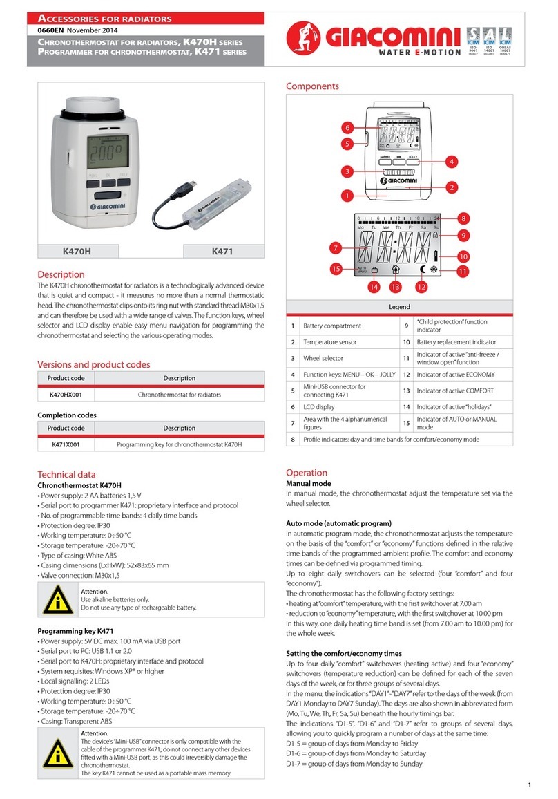
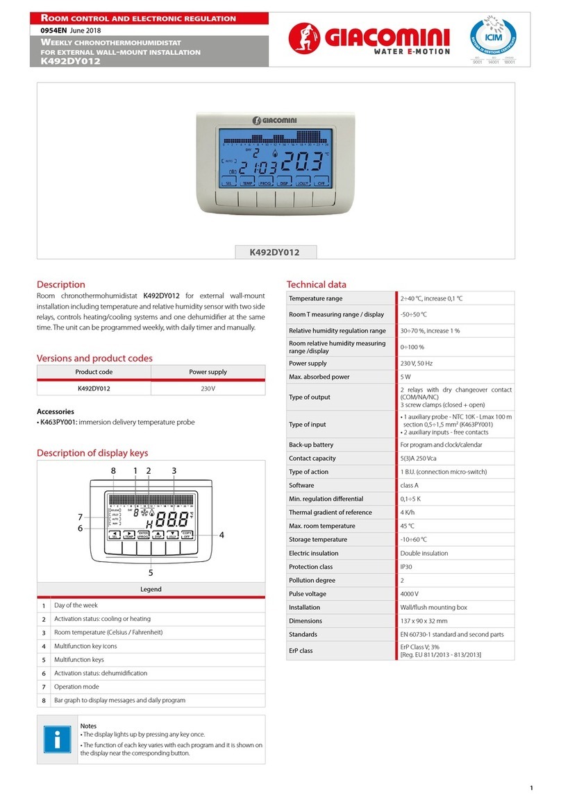
K495L
2
0680ML Maggio 2014 - May 2014
Termoregolazione - ThermoregulaTion
TermosTaTo ambienTe con sonda di TemperaTura e
umidiTà K495L
Room theRmostat K495L
ISO
14001
0032A/3
OHSAS
18001
0064L/1
ISO
9001
0006/7
Interfaccia seriale - Serial interface
Interfaccia seriale RS485 per la comunicazione con controllori, tramite
morsetti removibili a 3 vie. Utilizzare un doppino ritorto schermato, AWG20-
22 con lunghezza totale della rete non superiore a 500 m. La capacità tra i cavi
non deve essere maggiore di 90 pF/m.
Protocolli supportati: protocollo pLan (La rete pLAN è costituita da più
controllori e terminali collegati in rete che interagiscono tra loro scambiando
variabili e informazioni. Il limite sico di unità è 32 di cui al massimo 30
K495LY002).
RS485 serial interface for communication with controllers via 3 way plug-in
terminals. Use a twisted pair plus shielded cable, size AWG20-22. The total length
of the network must not exceed 500 m. The capacitance between the wires must
not exceed 90 pF/m.
Protocols supported: pLAN protocol (the pLAN network is made up of a series
of controllers and terminals connected in a network that interact and exchange
variables and information. The physical limit is 32 units, of which a maximum of
30 K495LY002 devices).
Avvertenze per l’installazione - Installation warnings
Evitare l’installazione delle schede in ambienti che presentino le seguenti
caratteristiche:
• umidità relativa maggiore di quanto indicato;
• forti vibrazioni o urti;
• esposizione a getti d’acqua;
• esposizione ad atmosfere aggressive ed inquinanti (es.: gas solforici e
ammoniacali, nebbie saline, fumi) con conseguente corrosione e/o ossidazione;
• elevate interferenze magnetiche e/o radiofrequenze (ad esempio vicino ad
antenne trasmittenti);
• esposizione all’irraggiamento solare diretto e agli agenti atmosferici in genere;
• ampie e rapide  uttuazioni della temperatura ambiente;
• ambienti ove sono presenti esplosivi o miscele di gas in ammabili;
• esposizione alla polvere (formazione di patina corrosiva con possibile
ossidazione e riduzione dell’isolamento).
Avoid installing the boards in environments with the following characteristics:
• relative humidity greater than the value speci ed;
• strong vibrations or knocks;
• exposure to jets of water;
• exposure to aggressive and polluting atmospheres(e.g.: sulphur and ammonia
fumes, saline mist, smoke) so as to
avoid corrosion and/or oxidation;
• strong magnetic and/or radio frequency interference (for example, near
transmitting antennae);
• exposure to direct sunlight and to the elements in general;
• large and rapid  uctuations in the room temperature;
• environments where explosives or mixes of  ammable gases are present;
• exposure to dust (formation of corrosive patina with possible oxidation and
reduction of insulation).
Avvertenze ulteriori - Further warnings
1. Una tensione di alimentazione elettrica diversa da quella prescritta può
danneggiare seriamente il sistema. Attenzione: qualora l’apparecchio venisse
adoperato in un modo non specicato dal costruttore, la protezione prevista
dall’apparecchio potrebbe essere compromessa.
2. Utilizzare capicorda adatti per i morsetti in uso. Allentare ogni vite ed inserirvi i
capicorda, quindi serrare le viti. Ad operazione ultimata tirare leggermente i cavi
per veri carne il corretto serraggio.
3. Per pulire il display usare un panno morbido. Non usare acqua.
4. L’uso a temperature particolarmente basse può causare una visibile
diminuzione della velocità di risposta del display. Questo è da ritenersi normale
e non è indice di malfunzionamento.
5. Il terminale deve essere  ssato a muro in modo da permettere il ricircolo
dell’aria attraverso le feritoie del guscio posteriore. Evitare i luoghi dove la misura
della temperatura ambiente può essere alterata, come ad esempio muri esterni,
nelle vicinanze di porte verso l’esterno o in esposizione al sole.
Nota. Note.
Adottare precauzioni contro le scariche elettrostatiche nel
maneggiare la scheda. Non avvicinarsi con le dita ai componenti
elettronici montati sulle schede per evitare scariche elettrostatiche
dell’operatore verso i componenti stessi.
Adopt precautions against electrostatic discharges when handling the
board. Do not touch or nearly touch the electronic components on the
boards so as to avoid electrostatic discharges from the operator to the
components.
Fig.1a
Fig.1b
Connessioni di alimentazione - Power supply connections
Rispettare le seguenti prescrizioni:
• I terminali di alimentazione del dispositivo sono chiamati G e G0. La
connessione avviene tramite morsetti a vite a 2 vie  ssati sul retro a muro
dello strumento. Utilizzare cavi con sezione da 0,5 a 1,5 mm2.
• Un fusibile obbligatorio dedicato da 250 mAT deve essere posto
esternamente tra l’alimentazione ed il terminale G.
• Utilizzare un trasformatore di sicurezza in classe 2 di almeno 4 VA.
• Se il trasformatore o alimentatore utilizzato per il dispositivo è lo stesso
anche per i controlli collegati tramite linea seriale, allora il terminale G0 del
K495LY002 deve essere connesso alla linea G0 dei controlli.
Importante: nel caso in cui sia richiesta la messa a terra di un terminale di
alimentazione, deve essere messo a terra il terminale G0 (e NON il terminale
G), sia per il K495LY002 che per gli altri dispositvi alimentati.
• L’alimentatore o il trasformatore di alimentazione utilizzato deve garantire un
isolamento doppio o rinforzato tra la rete a tensione pericolosa ed il terminale.
• la connessione tra i dispositivi bus deve essere necessariamente eettuata
“a catena”.
Observe the following warnings:
• The power supply terminals on the device are called G and G0. The power
connection is made using 2-way screw terminals on the rear of the instrument. Use
cables with a cross-section from 0.5 to 1.5 mm2
• A dedicated 250 mAT fuse must be installed externally between the power supply
and terminal G.
• Use a class 2 safety transformer with a minimum rating of 4 VA.
• If the same transformer or power supply is used for the device and for the controllers
connected via serial line, consequently terminal G0 on the K495LY002 must be
connected to the G0 line on the controllers.
Important: If a power supply requires the earth connection, use terminal G0 (and
NOT terminal G), both for the K495LY002 and the other powered devices.
• The power supply or the transformer used must guarantee double or reinforced
insulation between the high voltage mains and the terminal.
• the connections between the devices must be “chain” shape.
3
0680ML Maggio 2014 - May 2014
Termoregolazione - ThermoregulaTion
TermosTaTo ambienTe con sonda di TemperaTura e
umidiTà K495L
Room theRmostat K495L
ISO
14001
0032A/3
OHSAS
18001
0064L/1
ISO
9001
0006/7
Impostazione dei parametri bus - Bus setting parameters
Per visualizzare i parametri, premere e no alla comparsa della scritta
“par”, quindi rilasciare mantenendo premuto e premere , per 3 secondi.
Selezione e modi ca avvengono rispettivamente con , , .
Mentre il K495LY002 è connesso in pLan, qualora previsto dalla con gurazione
imposta dal software applicativo, la procedura di ingresso può essere sostituita
dalla pressione di uno speci co tasto. Per uscire salvando le impostazioni
mantenere premuto per 5 secondi.
La tabella seguente illustra il signicato dei parametri di funzionamento:
To display the parameters, press and until “par” is displayed, then release
while holding and press , for 3 seconds. Select and modify respectively using
, , .While K495LY002 is connected in pLAN, if available in the con guration
set by the application program, the access procedure may be replaced by pressing a
speci c button. To exit and save the settings, hold for 5 seconds.
The table below illustrates the meaning of the operating parameters:
Nome
Name
Descrizione
Description Min Max
Unità misura
Meas. unit
Default
Default
Da impostare
To be set
Ad02 1,6
Indirizzo di supervisione del K495LY002
(protocolli Modbus® e Proprietario)
K495LY002 supervisory address
(ModBus and Proprietary protocols)
1255 - 1 128/143
Br01 1,2 Baudrate di rete (protocollo pLAN)
Network Baudrate (pLAN protocoll) 0 1 - 0 -
Br02 1,3,6
Baudrate di supervisione
(protocolli Modbus® e Proprietario)
Supervisory Baudrate
(ModBus and Proprietary protocols)
0 4 - 4 -
En01 4Abilitazione buzzer
Enable buzzer 0 1 - 1 -
Pc01 Calibrazione sonda ambiente
Ambient probe calibration -9,9 9,9 °C /
°F 0,0 -
Prot 5,6 Protocollo seriale di comunicazione
Serial communication protocol 1 3 1 3
Fr01 Indicazione release rmware
Firmware release - - - -
(1) Il cambiamento di valore comporta la reinizializzazione della comunicazione.
Changing the value reinitialises communication.
(2) “0”corrisponde a 62.500 baud,“1”corrisponde a 115.200.
“0” corresponds to 62,500 baud, “1” corresponds to 115,200.
(3) “0”=1200 baud,“1”=2400 baud, “2”=4800 baud, “3”=9600 baud,“4”=19.200 baud.
“0” =1200 baud, “1”=2400 baud, “2”=4800 baud, “3”=9600 baud, “4”=19.200 baud.
(4) Posto a“0”indica che la funzione buzzer è disabilitata indipendentemente dal
comando del controllore. Questa funzione è signicativa soltanto se è presente
l’opzione buzzer.
Set to “0” indicates that the buzzer function is disabled irrespective of the controller
function. This function is only valid if the buzzer option is tted.
(5) “1”corrisponde a pLAN, “2”,“3”a ModBus.
“1” corresponds to pLAN, “2”, “3” to ModBus.
(6) Solo nella release rmware 1.3 ed eventuali future.
Only in  rmware 1.3 release and in the future.
Le funzioni che possono essere assegnate (da applicativo) ai tasti con
gurabili (KEY1...KEY6) oltre a quelle standard descritte nella tabella precedente
sono le seguenti:
The following functions can be assigned (by the application) to the buttons can be con
gured (KEY1 to KEY6), in addition the standard functions described in the table above:
Funzione
Function
Descrizione
Description
PRG Modica dei parametri / Set parameters
FAN Gestione ventole / Fan management
ALARM Riarmo manuale allarmi / Manual alarm reset
Per una descrizione dettagliata consultare il manuale dell’applicativo utilizzato.
Da applicativo è possibile gestire l’accensione di tutti i simboli/indicazioni.
For a detailed description see the manual for the application used. The application
can also manage the activation of all the symbols/indications.
6. Separare i cavi del dispositivo da cavi che alimentano carichi induttivi e di
potenza per evitare possibili disturbi elettromagnetici. Non inserire mai nelle
stesse canaline (comprese quelle dei cavi elettrici) cavi di potenza e cavi di
comunicazione seriale. Evitare che i cavi di comunicazione siano installati
nelle immediate vicinanze di dispositivi di potenza (contattori, dispositivi
magnetotermici o altro).
1. Using a di erent power supply from the one speci ed may seriously damage
the system; Important: if the appliance is used in a manner not speci ed by the
manufacturer, the rated protection of the appliance may be compromised;
2. Use cable ends suitable for the corresponding terminals. Loosen each screw and
insert the cable ends, then tighten the screws. When the operation is completed,
slightly tug the cables to check they are su ciently tight;
3. To clean the display, use a soft cloth. Do not use water;
4. Operation at particularly low temperatures may cause a visible decrease in the
response speed of the display. This should be considered normal and does not
indicate a malfunction;
5. The terminal must be fastened to the wall so as to allow the circulation of air
through the slits on the rear shell.
Avoid locations where the roomtemperature measurement may be altered, for
example outside walls, near doors leading to the outside, exposure to sunlight;
6. Separate the cables of the device from the cables to inductive loads and power
cables so as to avoid possible electromagnetic disturbance. Never insert power
cables (including the electrical cables) and serial communication cables in the same
conduits. Do not install the communication cables in the immediate vicinity of
power devices (contactors, circuit breakers or similar).
Interfaccia utente standard - Standard user interface
Nota. Note.
L’interfaccia utente graca può cambiare a seconda del software
applicativo del controllore che ne denisce la con gurazione.
The graphic user interface may change depending on the controller
application program that denes the conguration.
Assegnazione standard dei tasti in funzionamento normale
Standard assignment of the buttons in normal operation
La tabella riportata di seguito illustra le operazioni fondamentali svolte dai
tasti del dipositivo nella con gurazione standard. Le funzioni dei tasti KEY1...
KEY6 dipendono dalla congurazione imposta tramite il software applicativo
del modulo di regolazione.
The following table illustrates the fundamental operations carried out by the buttons
on the device in the standard con guration. The functions of buttons KEY1 to KEY6
depend on the con guration set by the controller application program.
Icona standard
Standard icon
Nome (standard)
Name (standard)
Descrizione
Description
KEY1 (POWER) Permette di accendere o di mettere in stand-by l’impianto
Used to switch the system on or to standby
KEY6 (TEMP) Visualizza temporaneamente informazioni alternative
Temporarily displays alternative information
UP, DOWN Impostano il set point di temperatura
Set the temperature set point
4
0680ML Maggio 2014 - May 2014
Termoregolazione - ThermoregulaTion
TermosTaTo ambienTe con sonda di TemperaTura e
umidiTà K495L
Room theRmostat K495L
ISO
14001
0032A/3
OHSAS
18001
0064L/1
ISO
9001
0006/7
Schemi elettrici - Electrical schemes
Testi di capitolato - Product specications
K495L
Termostato ambiente con display retroilluminato ed interfaccia locale per il controllo della temperatura e umidità ambiente. Da utilizzare con collegamento via bus al modulo
di regolazione KPM30 o KPM31. Alimentazione 24 Vac, comunicazione Modbus RTU slave su RS485. Installazione a parete in scatola civile a tre posti 503. Certicazione CE.
Room thermostat with backlight display and local interface to manage the room temperature and humidity. To use in combination with regulation units KPM30 or KPM31 by
bus connection. Modbus RTU slave on RS485. Wall mounting box with three module, 503 civil. CE certication.
Indicazioni display - Indications on the display
(*): dipende dalla con gurazione imposta dal software applicativo del controllore.
Allo startup compaiono le maschere di default “---”
e “----”/ depends on the con guration set by the controller program. At startup the “---”
and “----” screens are displayed as default
Avvertenza. Warning.
Separare quanto più possibile i cavi delle sonde e degli ingressi
digitali dai cavi dei carichi induttivi e di potenza per evitare possibili
disturbi elettromagnetici. Non inserire mai nelle stesse canaline
(comprese quelle dei quadri elettrici) cavi di potenza e cavi di segnale.
Separate as much as possible the probe and digital input signal cables
from the cables carrying inductive loads and power cables to avoid
possible electromagnetic disturbance. Never run power cables (including
the electrical panel wiring) and signal cables in the same conduits.
Dimensioni - Dimensions
Altre informazioni
Per ulteriori informazioni consultare il sito www.giacomini.com o contattare il servizio tecnico: '+39 0322 923372 6+39 0322 923255 *[email protected]
Questa comunicazione ha valore indicativo. Giacomini S.p.A. si riserva il diritto di apportare in qualunque momento, senza preavviso, modiche per ragioni tecniche o commerciali agli articoli
contenuti nella presente comunicazione. Le informazioni contenute in questa comunicazione tecnica non esentano l’utilizzatore dal seguire scrupolosamente le normative e le norme di
buona tecnica esistenti. Giacomini S.p.A. Via per Alzo, 39 - 28017 San Maurizio d’Opaglio (NO) Italy
Additional information
For additional information please check the website www.giacomini.com or contact the technical service: '+39 0322 923372 6+39 0322 923255 *[email protected]
This pamphlet is merely for information purposes. Giacomini S.p.A. retains the right to make modications for technical or commercial reasons, without prior notice, to the items described in
this pamphlet. The information described in this technical pamphlet does not exempt the user from following carefully the existing regulations and norms on good workmanship.
Giacomini S.p.A. Via per Alzo, 39 - 28017 San Maurizio d’Opaglio (NO) Italy

This manual suits for next models

1

Other Giacomini Thermostat manuals

Giacomini KPM10 User manual

Giacomini

Giacomini KPM10 User manual

Giacomini K470H Series User manual

Giacomini

Giacomini K470H Series User manual

Giacomini K492TY002 User manual

Giacomini

Giacomini K492TY002 User manual

Giacomini K495LY002 User manual

Giacomini

Giacomini K495LY002 User manual

Giacomini K492DY012 User manual

Giacomini

Giacomini K492DY012 User manual

Giacomini K470W User manual

Giacomini

Giacomini K470W User manual

Giacomini K470W User manual

Giacomini

Giacomini K470W User manual

Giacomini K492DY012 User manual

Giacomini

Giacomini K492DY012 User manual

Giacomini K470H User manual

Giacomini

Giacomini K470H User manual

Giacomini KD400 User manual

Giacomini

Giacomini KD400 User manual

Giacomini K494IY001 User manual

Giacomini

Giacomini K494IY001 User manual

Giacomini K495LY002 User manual

Giacomini

Giacomini K495LY002 User manual

Giacomini K470H User manual

Giacomini

Giacomini K470H User manual

Giacomini K470H User manual

Giacomini

Giacomini K470H User manual

Popular Thermostat manuals by other brands

OJ Microline UWG4 Sales Sheet

OJ

OJ Microline UWG4 Sales Sheet

LK Cq Assembly instruction

LK

LK Cq Assembly instruction

DELTA DORE 6050675 quick start guide

DELTA DORE

DELTA DORE 6050675 quick start guide

TERMA TT-IR user manual

TERMA

TERMA TT-IR user manual

Sanico 317469 manual

Sanico

Sanico 317469 manual

Horstmann HRT4-ZW User and installation instructions

Horstmann

Horstmann HRT4-ZW User and installation instructions

Sunvic TL ONE installation guide

Sunvic

Sunvic TL ONE installation guide

brennenstuhl HT CZ 01 manual

brennenstuhl

brennenstuhl HT CZ 01 manual

Honeywell T7512A user guide

Honeywell

Honeywell T7512A user guide

Willhi WH7016E product manual

Willhi

Willhi WH7016E product manual

Pro1 Technologies T701i Product installation guide

Pro1 Technologies

Pro1 Technologies T701i Product installation guide

Bay Controls BW-WT2 owner's manual

Bay Controls

Bay Controls BW-WT2 owner's manual

First Alert Onelink THERM-500 quick start guide

First Alert

First Alert Onelink THERM-500 quick start guide

Rogers Nest Thermostat Setup guide

Rogers

Rogers Nest Thermostat Setup guide

Action Talking Products Kelvin Operation manual

Action Talking Products

Action Talking Products Kelvin Operation manual

Regulus TP44 Installation and operation manual

Regulus

Regulus TP44 Installation and operation manual

JUMO B 70.1050.0 operating instructions

JUMO

JUMO B 70.1050.0 operating instructions

Atag EaZy quick start guide

Atag

Atag EaZy quick start guide

manuals.online logo
manuals.online logoBrands
  • About & Mission
  • Contact us
  • Privacy Policy
  • Terms and Conditions

Copyright 2025 Manuals.Online. All Rights Reserved.