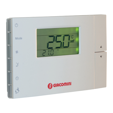
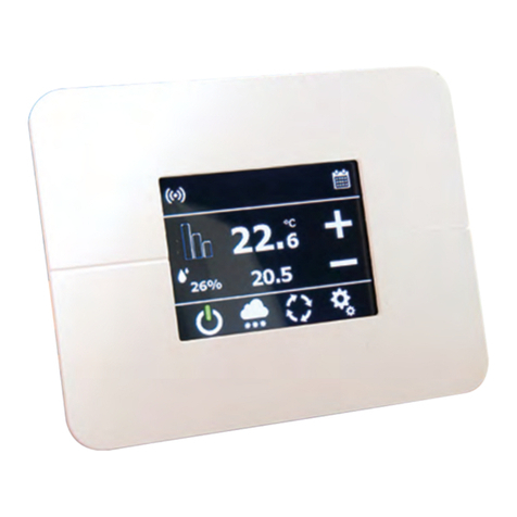
Giacomini KPM10 User manual

1
0822EN January 2019
ThermoregulaTion
Single zone room controller for heating and
cooling with temperature and humidity SenSor
included - Kpm10
047U54478
Installation
Open the product by detaching the front part from the mounting base,
as shown in Fig. 1:
• Using a screwdriver, remove the screw holding the tab in the opening.
• Once having removed the screw, slide the plastic tab as shown in the gure
so as to remove it from the instrument and be able to lever the catch.
• To open the instrument, press the tab on the front by inserting a athead
screwdriver into the slit in the middle on the bottom of the case and at the
same time ip the front panel upwards.
Fig. 1
• Once having completely removed the cover of the instrument, the two
parts remain connected by a at cable that can be disconnected from the
front panel.
• Fasten the bottom of the clima to the wall using the screws contained in
the packaging.
• To connect the wires to the terminal block, remove the terminal covers by
squeezing the two ns.
• Make the required connections according to the model chosen, running
the connection cables through the hole in the middle of the bottom shell
and connecting them to the terminal block, observing the indications on the
label. Separate the connection and control cables from the relay cables.
Warning.
Make sure all the power supply lines have been connected, both low
voltage (24 Vac/dc) and, where necessary, high voltage for the relays
(230 V), before reconnecting the front part of the instrument using
Front-Rear at cable.
Note.
For the purposes of electrical safety (EN60730-1), once the controller
has been installed, tighten the plastic tab in the housing for opening
the instrument.
Description
The KPM10 single zone room controller for heating and cooling with
temperature and humidity sensor included, in combination with K463P
delivery temperature probe, allows the ambient temperature and humidity
regulation combined with mixing valve manage to control the delivery
temperature. The KPM10 controller is equipped with 2 relay commands for
control of the circulator and the dehumidier. The mixing valve manage
according to the logic proportional / integral / derivative is controlled in a
voltage of 0...10 V. The selection of winter/summer mode is done by applying
the 24 V voltage to the dedicated digital input.
Versions and product codes
Product code Supply
KPM10Y001 24 Vac
Completion codes
•K463PY001: delivery temperature probe
Technical data
• Power supply: 24 Vac +10...15%, 50/60 Hz, 1 VA / 24...32 Vdc, 1 W
Safety power supply: class 2 / Min. cable cross-section 0,5 mm2 / Power
supply compatible with compactSteam (G-G0)
• Operating temperature: 0÷60 °C, 10÷90% rH not-condensing
• Storage temperature: -20÷70 °C, 10÷90% rH not-condensing
• Environmental pollution: normal
• Pollution: degree II
• Software class and structure: A
• Type of action: 1C
• Index of protection: IP20
• Ball pressure test temperature on plastic of front casing: 125 °C
• Classication according to protection against electric shock:
2, to be integrated into class 1 or 2 appliances
• Period of stress across the insulating parts: long
• Immunity against voltage surges: category 2
• Wire cross-section: 0,5÷1,5 mm2
• Precision of inside temperature measurement: ± 1 °C from 0 to 60 °C
• Precision of outside temperature measurement: NTC (10 kΩ) range -40÷80 °C
precision ± 0,5 °C + sensor precision:
± 1 °C from 0 to 40 °C / ± 1,5 °C from -40 to 0 °C and from 40 to 80 °C
• 0 to 10 V analogue output, not isolated, for proportional control:
precision ± 5 % max load 5 kΩ, max current 2 mA
• Relay approval: EN60730-1: NO 1(1)A 250 Vac cos = 0,4, 100.000 cycles
UL-873: NO 1 A resistive 24 Vac, 30 Vdc, 100.000 cycles
PILOT DUTY: 24 Vac, make 15 A, break 1 A, 30.000 cycles
• Precision of humidity measurement range 10...90 %: ± 3 % rH at 25 °C
± 5 % rH 0 to 60 °C
• Energy eciency class ErP: class 4 + 4 %
KPM10

2
0822EN January 2019
ThermoregulaTion
Single zone room controller for heating and
cooling with temperature and humidity SenSor
included - Kpm10
047U54478
Conguration
Connector Function
FLAT front-rear The at front/rear connection cable must be reconnected in the position dened by the plastic part to ensure correct polarity
Dip-switches For conguring operation mode (to set: OFF - ON - OFF - OFF)
Dip-switches: OFF - ON - OFF - OFF
FLAT front-rear
Electrical connections
1
2
3
4
5
6
7
8
9
10
11
1(1)A
1(1)A
G0
G24Vac
OUT 0..10V
G0
NTC
sonda/probe
D IN
D IN
L
N
M
~
TRASFORMATORE
230Vac
3
1
4
5
6
TERMOSTATO DI SICUREZZA K373
SONDA A IMMERSIONE
CIRCOLATORE
CIRCULATOR
SONDA A IMMERSIONE K463PY001
24Vac
MOTORE
VALVOLA
MISCELATRICE
0...10V
COMANDO DEUMIDIFICATORE
24Vac
SAFETY THERMOSTAT K373
IMMERSION PROBE
SWITCHING SUMMER (CLOSED) / WINTER (OPEN)
SENSOR FLOW K463PY001
COMMUTAZIONE ESTATE (CHIUSO)/INVERNO (APERTO)
MIX
SERVOMOTOR
0...10V
TRANSFORMER
DEHUMIDIFIER CONSENT
Relè 24Vac
KPM10Y001
230Vac/24Vac 5VA
Wiring
Digital input With external power supply to 24 Vac contact: class 2 safety external power supply separate from the 24 Vac power supply to the instrument
Digital input connection Maximum length 10 m, min. cable cross-section 0.5 mm2.
Analogue output connection Maximum length 10 m, min. cable cross-section 0.5 mm2.
Relay output connections Maximum length 30 m, cable cross-section from 1.5 to 2.5 mm2, class 2 reinforced insulation from the instrument. Basic insulation between the relays.
UL speci cations for
connections
Use copper wires approved for a temperature of 75 C. Minimum cross-section AWG 22-14 rigid or exible. To tighten the terminals, apply a torque
of 7 Lb/In for the black terminals (SAURO). To use the instrument in compliance with UL-873, a load with a maximum voltage 24 Vac, class 2, can
be connected to the relay output.
Warning.
All the connections, except for the relays, must be connected to very
low voltage circuits with reinforced insulation.

3
0822EN January 2019
ThermoregulaTion
Single zone room controller for heating and
cooling with temperature and humidity SenSor
included - Kpm10
047U54478
Display and buttons
Side programming
buttons
Immediately change
the current set point
LCD display
Display description
Legend
1LARGE eld - Displays the temperature/humidity
2Mode for setting the active value on the large display
3Night mode symbol. If o = daytime mode
4Lock mode. The parameter is not accessible
5Active time bands
6Outside/inside/maximum/minimum temperature symbol
7Mode for setting the active value on the small display
8Auto operating mode
9SMALL eld - Displays the temperature/humidity
10 Dehum. ( ) /humid. ( ) operation. When the ramp symbol is on the
corresponding mode is active
11 Heating( ) /cooling ( ) operation. When the ramp symbol is on the
corresponding mode is active
Buttons description
Buttons Description
KPM10 ON/OFF
Selects the temperature display mode, degrees Celsius or Fahrenheit.
Whenever pressed switches the temperature units.
Used to display and where necessary change, using the UP and DOWN
buttons, the set point displayed in the SMALL eld.
If held for more than 5 sec accesses the parameters menu.
To scroll the various parameters use UP and DOWN. To edit them press
the SET button a second time and to exit the parameters menu press
the PRG button. Access to the parameters is protected by password if
parameter PS is enabled.
Change mode manually: activates the opposite function (and the
corresponding set point) to the current (night if day or day if night), for
the set time. To change or reset the timer use the UP and DOWN buttons
to increase or decrease the time.
Press a second time to exit and return to the main menu.
If sleep mode is already active, pressing the button shows the time
remaining on the timer.
E.g..: if the clima is in Night mode (moon symbol on) from time band,
pressing this button activates daytime mode (moon symbol o ) for the
set time.
Accesses the menu for setting the clock, the time bands, and the default
value of the timer. When rst pressed displays the current time (RTC); to
display the other parameters, use the UP and DOWN arrows.
To set a new value, press SET when displaying the desired parameter and
change the value using the UP and DOWN buttons.
Press a second time to exit and return to the main menu.
Accesses the menu for displaying the temperature: current, maximum
and minimum outside (from instrument power on), inside and outside.
To display the various temperatures, press the button repeatedly.
Their meaning is displayed in the box with the home symbol.
Also displays the value of the analogue output when “Out” is shown in
the SMALL eld.
From the main menu increases the value of the set point displayed in the
LARGE eld. In the other menus displays the variables or the parameters,
or alternatively sets the value after having pressed SET.
From the main menu decreases the value of the set point displayed in the
LARGE eld. In the other menus displays the variables or the parameters,
or alternatively sets the value after having pressed SET.
The values displayed in the LARGE and SMALL elds depend on the setting of
parameter dyS, as shown in the following table:
dyS temper. and humidity LARGE eld SMALL eld
1Humidity Temperature
2 Temperature Humidity
3Temperature set point Humidity set point
4Humidity set point Temperature set point
dyS parameter must be set at 2.

4
0822EN January 2019
ThermoregulaTion
Single zone room controller for heating and
cooling with temperature and humidity SenSor
included - Kpm10
047U54478
Main parameters to be set
The parameters for each operating mode also feature a default value, and
these values can be restored by running the “Factory set” operation.
See the table of parameters for details of the default values and settings.
Code Parameter
Range
Default
UOM.
Giacomini
Standard
Day temperature set point in cooling 10...50 24.0 °C
Night temperature set point in cooling 10...50 26.0 °C
Day temperature set point in heating 10...50 20.0 °C
Night temperature set point in heating 10...50 18.0 °C
tHH High water temperature limit in heating 15...80 45,0 °C
tHL Low water temperature limit in heating 15...80 23,0 °C
tHH High water temperature limit in cooling 5...35 30,0 °C
tHL Low water temperature limit in cooling 5...35 10,0 °C
tAH High room temperature limit in heating 15...40 24,0 °C
tHL Low room temperature limit in heating 15...40 16,0 °C
tAH High room temperature limit in cooling 5...35 30,0 °C
tAL Low room temperature limit in cooling 5...35 16,0 °C
dfA Temperature dierential of water temperature
controll 0...20 20 °C 20
tlA Integration time in seconds to calculate integral
error in the water temperature control algorithm 0...999 100 sec. 100
tdA Derivate time in seconds to calculate derivate
error in the water temperature control algorithm 0...999 20 sec. 20
tIn Integration time in minutes to calculate integral
error in the water temperature control algorithm 1...100 10 min.
tr
Observation time for compensation of the water
temperature limit
(OFF = compensation not enabled)
OFF...225 OFF min.
ddP Dewpoint delta for adjusting the water
temperature set point -20...20 0,0 °C
EdP Enable water temperature set point limit to avoid
condensation no, yes no - YES
Humidication set point 10...70 50,0 % rH 10
Dehumidication set point 10...70 70,0 % rH 60
dFH Humidity dierential for the activation of the
analogue output and the relay 1...20 5.0 % rH
dFd Dehumidication dierential for the activation
of the relay 1...20 5.0 % rH
SFH
Parameter to de ne the humidication/
dehumidication status in day and night mode:
Activates or deactivates humidic. or dehumidic.
control (based on DIP4) with the time bands.
The parameter can have the following values:
0 - Time bands disabled. The humidication/
dehumidication control is always active, if
featured, and is congured in relation to DIP4.
1 - Time bands enabled. When switching to the
daytime band, humidication/dehumidication
control (depends on DIP4) is activated.
When switching to the night band,
humidication/dehumidication control
(depends on DIP4) is deactivated.
2 - Time bands enabled. When switching to the
daytime band, humidication/dehumidication
control (depends on DIP4) is deactivated.
When switching to the night band,
humidication/dehumidication control
(depends on DIP4) is activated.
0...2 0 -
AUt
Humidity set point automatically compensated
by the outside temperature.
If humidity control is featured, the ambient
humidity is controlled with an automatic set
point, dened from 1H to 7H using the buttons,
as specied in the corresponding table.
If set to OFF the mode is disabled.
Setting one of the levels in the table, the
controller independently sets a humidity set
point in relation to the outside temperature.
OFF
1H...7H OFF -
CSt
Parameter for set point compensation.
Parameter CSt enables and sets the gain for set
point compensation according to the outside
temperature.
If CSt = 0 compensation is disabled.
Also see parameters Ctt and CtS.
-1...1 0,0 °C
CdF
Max dierential for the compensated set point.
The maximum value for the compensated set
point is limited by this parameter. In heating
mode, if the dierence calculated for set point
compensation is higher than CdF, the instrument
uses CdF as the maximum dierence from the
set point.
Similarly, in cooling mode if the dierence
calculated for set point compensation is less than
CdF, the instrument uses CdF as the maximum
dierence from the set point.
0...20 2.0 °C
Ctt
Threshold for set point compensation in heating
mode Temperature set point compensation
in heating based on the outside temperature
measurement:
compensed setpoint = setpoint – (setpoint –
Text – Ctt) * CSt
Compensation is activated only if:
Text < setpoint – Ctt
0...25 10.0 °C
CtS
Threshold for set point compensation in cooling
mode.
Temperature set point compensation in cooling
based on the outside temperature measurement:
compensed setpoint = setpoint + (Text –
setpoint – CtS) * CSt
Compensation is activated only if:
Text > setpoint + CtS
0...25 10.0 °C
AdC
Con guration T2A e T2A+H:
Additional modes for the automatic operation:
For temperature control only (T2A):
Conguration 1: temperature control with set
point and dead band only (2xdS1).
Conguration 2: temperature control only with
automatic changeover of the set point.
Conguration 3: temperature control only
with cooling and heating set point, automatic
changeover and manual ON/OFF control for
outlet fan.
1...3
1
-
For temperature + humidity control (T2A+H):
Conguration 1: temperature control with set
point and dead band only (2xdS1).
Two set points for humidity.
Conguration 2: temperature and humidity
control with cooling and heating set point and
automatic changeover.
1...2 -
dyS
Active display con guration.
Used to set the values shown in the large and
small elds on the display.
1...4 1 - 2
rtC
Current time.
The large eld displays the hours and the small
eld the minutes.
00:00
23:59 00:00 h
SLP
Duration of manual day-night mode changeover.
The large eld displays the hours and the small
eld the minutes (15 minute steps)
0...12 8 h h
dAy
Day band threshold.
The large eld displays the hours and the small
eld the minutes (15 minute steps)
00:00
23:59 8:00 h
nlt Night band threshold.
The large eld displays the hours and the small
eld the minutes (15 minute steps)
00:00
23:59 20:00 h
dl
Digital input conguration:
OFF: disabled
1 select remote cooling /heating
2 remote ON/OFF
3 select day/night (alternative set)
4 remote alarm
OFF...4 OFF - 1
POL
Digital contact polarity.
Used to choose whether to consider the digital
input active when closed or open or alternatively
whether or not there is voltage in the optically-
isolated version.
Voltage-free contact:
nE: active when the input is closed
PO: active when the input is open
Optically isolated:
nE: active when voltage is present at the input
PO: active when voltage is not present at the input
nE, PO nE -PO
5
0822EN January 2019
ThermoregulaTion
Single zone room controller for heating and
cooling with temperature and humidity SenSor
included - Kpm10
047U54478
El
Control cooling/heating operating mode.
Enables the possibility to de ne the operating
mode, cooling/heating, by parameter rather than
by DIP 4.
dIS: Parameter EI is disabled, cooling/heating
mode is selected by DIP 4 on the rear.
En: Parameter EI is enabled, cooling/heating
mode is selected by parameter EI.
dIS, En dIS -
El
Select cooling/heating operation only active if
this mode is enabled by the previous parameter.
Selects the mode, cooling or heating.
E: The instrument works in cooling mode
I: The instrument works in heating mode
E, I E -
LIn
Instrument output control mode.
Enabling this parameter allows the outputs to
be controlled directly via the serial connection.
Warning, if enabled no control is performed
independently by the instrument.
If active and the supervisor does not query the
instrument for more than two minutes, the
outputs are automatically disabled and the no
link error (ELn) is signalled on the display.
no: the function is disabled.
yES: the function is enabled.
no, yES no -
CAL+Int Inside temperature calibration, digital sensor or
NTC.
Within a maximum of ± 10 °C
-10...10 0.0 °C
CAL+ESt Outside temperature calibration, NTC sensor.
Within a maximum of ± 10 °C -10...10 0.0 °C
CAL+HUn Digital humidity sensor calibration.
Within a maximum of ± 15 % rH. -15...15 0.0 % U.R.
LE
Parameter access level. Level of access the control
parameters for the active mode:
Level 1: basic access, only the essential parameters
for correct operation.
Level 2: advanced access, used to set all the
parameters for the selected control mode.
1, 2 1 -
LOC
Lock. The lock parameter used to disable some
functions of the instrument, as per the following
settings:
LOC = OFF.
LOC = 1: The UP/DOWN and time bands buttons
are disabled.
LOC = 2: Only the time bands button is disabled.
In these cases, the LOCK symbol is shown on the
display whenever attempting to perform an
unauthorised operation.
OFF...2 OFF -
Unt
Temperature display mode.
Sets the temperature display mode, in degrees
Fahrenheit or Centigrade.
Unlike direct selection using the button, if
changing the temperature display mode using
parameter Unt, this becomes the default display
mode when switching the instrument on.
°C, °F °C -
nEd
Parameter for control with average value sensor
values. Denes the average control temperature
(Tm), based on the weighted average of the inside
temperature (TI) and outside temperature (TE).
Both the measurements must be valid and Tm is
achieved with the following formula:
Tm = (TI * (100- nEd) + TE * nEd) /100
The average temperature calculated is used for
control and display.
0...100 0.0 %
Add
RS485 serial address (the external option code
IROPZ48500 is required). It can be read by the
supervisor and can only be changed with direct
access on the instrument.
1...207 1 -
SEr
Select serial communication protocol:
0: Owner protocol 9.6 kb/s
1: Owner protocol 19.2 kb/s
2: Modbus 9.6 kb/s, even parity, 8 bits, 1 stop
3: Modbus 19.2 kb/s, even parity, 8 bits, 1 stop
4: Modbus 9.6 kb/s, no parity, 8 bits, 2 stop
5: Modbus 19.2 kb/s, no parity, 8 bits, 2 stop
0...5 1 - 3
PS
Password for accessing the parameters
Set to 0: no password is required.
Set other than zero: the same value must be
entered to access the parameters.
0...999 0 -
FAC+SET
Factory set.
Reset the default values (manufacturer) on the
instrument for the current mode.
no, yES no -
•Clock, TIME BANDS Prg/ (clock):
press the corresponding button to display and if necessary set the default
duration of the change mode timer, display or set the RTC clock and set the
Day and Night time bands.
rtC clock hh:mm -
SLP manual changeover duration default 8 h.
dAy start day band default 08:00
nlt start night band default 20:00
Once having displayed the desired parameter using the UP/DOWN buttons,
press SET and the parameter starts ashing.
Edit the value using the UP/DOWN buttons and then press SET.
To exit the menu, press the PRG button again.
To disable the time bands function, set parameter rtC o:
• Select parameter rtC using PRG/CLOCK and set the value using the DOWN
button.
• When reaching 00:00 using the DOWN button the function will be o.
When parameter rtC is set to o the operating mode is always daytime, and
consequently only the daytime set points are used, the night settings are only
used when the NIGHT button is pressed, manually changing mode.
The same is true for models without the RTC function. When the time bands
are set, the CLOCK symbol is shown on the display.
Additional functions
The controller features a series of additional functions, as described below.
Change night/day mode manually (night)
This activates the opposite function to the current (night if day or day if night),
for the set time.
Pressing the NIGHT button once accesses the timer menu and displays the
duration.
To change the duration of the temporary mode use the UP/DOWN buttons.
To change the value of the timer permanently, access the Prg menu and set
parameter SLP.
To set the current timer to zero and return the instrument to the original mode,
press the NIGHT button, the remaining time is displayed, then press DOWN
until reaching the value 0. The instrument, after having briey displayed the
message OFF SLP, automatically returns to the main menu. Once having set
the timer, pressing the NIGHT button displays the time remaining on the
timer. This value can be changed at any time.
To exit the menu press the NIGHT button again.
Example of operation with time bands:
RTC: tted and con gured, the time is 15:55, the symbol is on
dAy: 8:00
nIt: 16:00
At 16:00 the controller will switch to Night mode with a lower (in heating) or
higher (in cooling) temperature setting.
Assuming the user wants to extend Day mode for a further 3 hours, having to
work late in the oce.
The following operations are required:
• press the NIGHT button;
• set the timer to 3h and 00’ using the DOWN button;
• press the NIGHT button to conrm the setting.
The KPM10 returns to Day mode with the corresponding set point. It will
automatically return to Night mode according to the time bands when the
timer reaches zero.

6
0822EN January 2019
ThermoregulaTion
Single zone room controller for heating and
cooling with temperature and humidity SenSor
included - Kpm10
047U54478
Sensor calibration
To make up for any errors due to the length of the cables or the sensors
connected, the controller features two parameters for calibrating the values
read by the sensors. The following parameters are involved:
Code Parameter
Range
Default
UOM.
Giacomini
Standard
CAL+Int Inside temperature calibration, digital sensor
or NTC.
Within a maximum of ± 10 °C.
-10...10 0.0 °C
CAL+ESt Outside temperature calibration, NTC sensor.
Within a maximum of ± 10 °C. -10...10 0.0 °C
CAL+HUn Digital humidity sensor calibration.
Within a maximum of ± 15% rH. -15...15 0.0 % rH
Password
On all models a password (PS) can be set for accessing the parameters. Once
the value of PS has been set (other than zero), this value must be entered in
order to access the parameters.
Nota.
Make sure the password is kept in a safe place, as without it the
parameters can no longer be accessed. The value can only be reset
from the supervisor or using the parameter copying key.
Code Parameter
Range
Default
UOM.
Giacomini
Standard
PS
Password for accessing the parameters.
Set to 0: no password is required to access the
parameters. Set other than zero: the same value
must be entered to access the parameters.
0...999 0 -
Antifreeze
To prevent the formation of ice and frost, the controller features the antifreeze
function, which activates the relay dedicated to the temperature function
regardless of the control mode, when in heating operation. Antifreeze is
available in all control modes, apart from humidity only, and the corresponding
relay is activated when the temperature falls below 5 °C. The function is also
active when the instrument is o and is enabled 20 seconds after shutdown.
Alarms and messages
Code on
display Description Reset Eect
EE System/memory error Manual Stops all outputs
Eth Temperature+humidity sensor fault Automat.
Stops all outputs and
disables the calculation of
the dewpoint
E1 Built-in NTC temperature sensor fault Automat. Stops all outputs
E2 Remote temperature sensor fault Automat.
Stops compensation if active,
and control on average if
enabled
Ert RTC alarm Automat. -
EHi High control temperature alarm,
radiant oor Automat. Stops all outputs
ELo Low control temperature alarm,
radiant oor Automat. Stops all outputs
ELn Serial connection alarm Automat. Only active if I/Os managed
via serial connection
ALE External alarm from digital input Automat. Signal-only alarm from
external contact (humidier)
Nota.
When the value is not shown in the SMALL or LARGE eld,
three dashes “---“ are displayed.
Dimensions
36 mm
Warning.
The customer must only use the product in the manner described in
the documentation relating to the product.
In addition to observing any further warnings described in this manual,
the following warnings must be heeded for all products:
• prevent the electronic circuits from getting wet. Rain, humidity and
all types of liquids or condensate contain corrosive minerals that may
damage the electronic circuits. In any case, the product should be
used or stored in environments that comply with the temperature and
humidity limits speci ed in the manual;
• do not install the device in particularly hot environments. Too high
temperatures may reduce the life of electronic devices, damage them
and deform or melt the plastic parts. In any case, the product should
be used or stored in environments that comply with the temperature
and humidity limits speci ed in the manual;
• do not attempt to open the device in any way other than described
in the manual;
• do not drop, hit or shake the device, as the internal circuits and
mechanisms may be irreparably damaged;
• do not use corrosive chemicals, solvents or aggressive detergents to
clean the device;
• do not use the product for applications other than those speci ed in
the technical manual.

7
0822EN January 2019
ThermoregulaTion
Single zone room controller for heating and
cooling with temperature and humidity SenSor
included - Kpm10
047U54478

8
0822EN January 2019
ThermoregulaTion
Single zone room controller for heating and
cooling with temperature and humidity SenSor
included - Kpm10
047U54478
IT AVVERTENZE PER IL CORRETTO SMALTIMENTO DEL PRODOTTO
Questo prodotto rientra nel campo di applicazione della Direttiva 2012/19/UE riguardante la gestione dei riuti di apparecchiature elettriche ed elettroniche (RAEE).
L’apparecchio non deve essere eliminato con gli scarti domestici in quanto composto da diversi materiali che possono essere riciclati presso le strutture adeguate.
Informarsi attraverso l’autorità comunale per quanto riguarda l’ubicazione delle piattaforme ecologiche atte a ricevere il prodotto per lo smaltimento ed il suo
successivo corretto riciclaggio.
Si ricorda, inoltre, che a fronte di acquisto di apparecchio equivalente, il distributore è tenuto al ritiro gratuito del prodotto da smaltire.
Il prodotto non è potenzialmente pericoloso per la salute umana e l’ambiente, ma se abbandonato nell’ambiente impatta negativamente sull’ecosistema.
Leggere attentamente le istruzioni prima di utilizzare l’apparecchio per la prima volta.
Si raccomanda di non usare assolutamente il prodotto per un uso diverso da quello a cui è stato destinato, essendoci pericolo di shock elettrico se usato
impropriamente.
Il simbolo del bidone barrato, presente sull’etichetta posta sull’apparecchio, indica la rispondenza di tale prodotto alla normativa relativa ai riuti di
apparecchiature elettriche ed elettroniche.
L’abbandono nell’ambiente dell’apparecchiatura o lo smaltimento abusivo della stessa sono puniti dalla legge.
EN IMPORTANT INFORMATION FOR CORRECT DISPOSAL OF THE PRODUCT
This product falls into the scope of the Directive 2012/19/EU concerning the management of Waste Electrical and Electronic Equipment (WEEE).
This product shall not be dispose in to the domestic waste as it is made of dierent materials that have to be recycled at the appropriate facilities.
Inquire through the municipal authority regarding the location of the ecological platforms to receive the product for disposal and its subsequent correct recycling.
Furthermore, upon purchase of an equivalent appliance, the distributor is obliged to collect the product for disposal free of charge.
The product is not potentially dangerous for human health and the environment, but if abandoned in the environment can have negative impact on the
environment.
Read carefully the instructions before using the product for the rst time.
It is recommended that you do not use the product for any purpose rather than those for which it was intended, there being a danger of electric shock if used
improperly.
The crossed-out wheeled dustbin symbol, on the label on the product, indicates the compliance of this product with the regulations regarding Waste
Electrical and Electronic Equipment.
Abandonment in the environment or illegal disposal of the product is punishable by law.
FR AVERTISSEMENTS POUR L’ÉLIMINATION CORRECTE DU PRODUIT
Ce produit entre dans le champ d’application de la directive 2012/19 / UE relative à la gestion des déchets équipements électriques et électroniques (DEEE).
L’appareil ne doit pas être jeté avec les ordures ménagères car il est fait de diérents matériaux pouvant être recyclés dans des centres appropriés.
Renseignez-vous auprès de l’autorité locale concernant l’emplacement des plates-formes écologiques appropriées pour recevoir le produit pour sa destruction
et son recyclage correct ultérieur.
Il convient également de rappeler que, en cas d’achat d’un appareil équivalent, le distributeur est tenu de collecter le produit à détruire.
Le produit n’est potentiellement pas dangereux pour la santé humaine et l’environnement, mais s’il est abandonné dans l’environnement, il a un impact négatif
sur l’écosystème.
Lisez attentivement les instructions avant d’utiliser l’appareil pour la première fois.
Il est interdit d’utiliser le produit pour un usage diérent de celui auquel il était destiné, il y a risque de choc électrique si utilisé incorrectement.
Le symbole de la poubelle barrée sur l’étiquette de l’appareil indique sa correspondance produit à la législation relative aux déchets d’équipements
électriques et électroniques.
L’abandon dans l’environnement de l’équipement ou l’élimination illégale de l’équipement est punissable par la loi.
DE WICHTIGE HINWEISE ZUR KORREKTEN ENTSORGUNG DES PRODUKTS
Dieses Produkt fällt in den Anwendungsbereich der Richtlinie 2012/19/EU über die Entsorgung von Elektro- und Elektronik - Altgeräten (WEEE).
Dieses Produkt darf nicht in den Hausmüll entsorgt werden, da es aus verschiedenen Materialien besteht, die in entsprechenden Einrichtungen recycelt werden
müssen.
Erkundigen sie sich bei ihrer Gemeinde nach dem Standort des nächsten Recyclinghofs bzw. der nächsten Annahmestelle, um das Produkt dem Recycling
zuzuführen bzw. fachgerecht zu entsorgen.
Darüber hinaus ist der Händler verpichtet, das Produkt beim Kauf eines gleichwertigen Geräts kostenlos zu entsorgen.
Das Produkt ist für die menschliche Gesundheit und die Umwelt potenziell nicht gefährlich.
Diese können sich aber, falls sie in der Umwelt gelangen, negativ auf diese auswirken.
Lesen Sie daher vor dem ersten Gebrauch des Produkts die Inbetriebnahme-, Bedienungs- und Entsorgungsanweisungen sorgfältig durch. Es wird empfohlen,
dass Sie das Produkt nur für den vorgesehenen Zweck verwenden.
Bei unsachgemäßer Verwendung bzw. Fehlgebrauch besteht die Gefahr eines elektrischen Schlags.
Das Symbol der durchgestrichenen Mülltonne auf dem Etikett des Produkts weist auf die Konformität dieses Produkts zu den Vorschriften für Elektro-
und Elektronik-Altgeräte hin. Das Ablagern in der Umwelt oder die illegale Entsorgung des Produkts ist strafbar.
Safety Warning. Installation, commissioning and periodical maintenance of the product
must be carried out by qualied operators in compliance with national regulations and/or local
standards. A qualied installer must take all required measures, including use of Individual
Protection Devices, for his and others’ safety. An improper installation may damage people,
animals or objects towards which Giacomini S.p.A. may not be held liable.
Additional information. For more information, go to giacomini.com or contact our technical
assistance service. This document provides only general indications. Giacomini S.p.A. may
change at any time, without notice and for technical or commercial reasons, the items included
herewith. The information included in this technical sheet do not exempt the user from strictly
complying with the rules and good practice standards in force.
Table of contents
Other Giacomini Thermostat manuals

Giacomini
Giacomini K470H User manual

Giacomini
Giacomini K470H User manual

Giacomini
Giacomini KD400 User manual

Giacomini
Giacomini K492TY002 User manual

Giacomini
Giacomini K495L User manual

Giacomini
Giacomini K492DY012 User manual

Giacomini
Giacomini K470W User manual

Giacomini
Giacomini K495LY002 User manual

Giacomini
Giacomini K492DY012 User manual

Giacomini
Giacomini K470W User manual