Mode
135 mm 30
86 mm
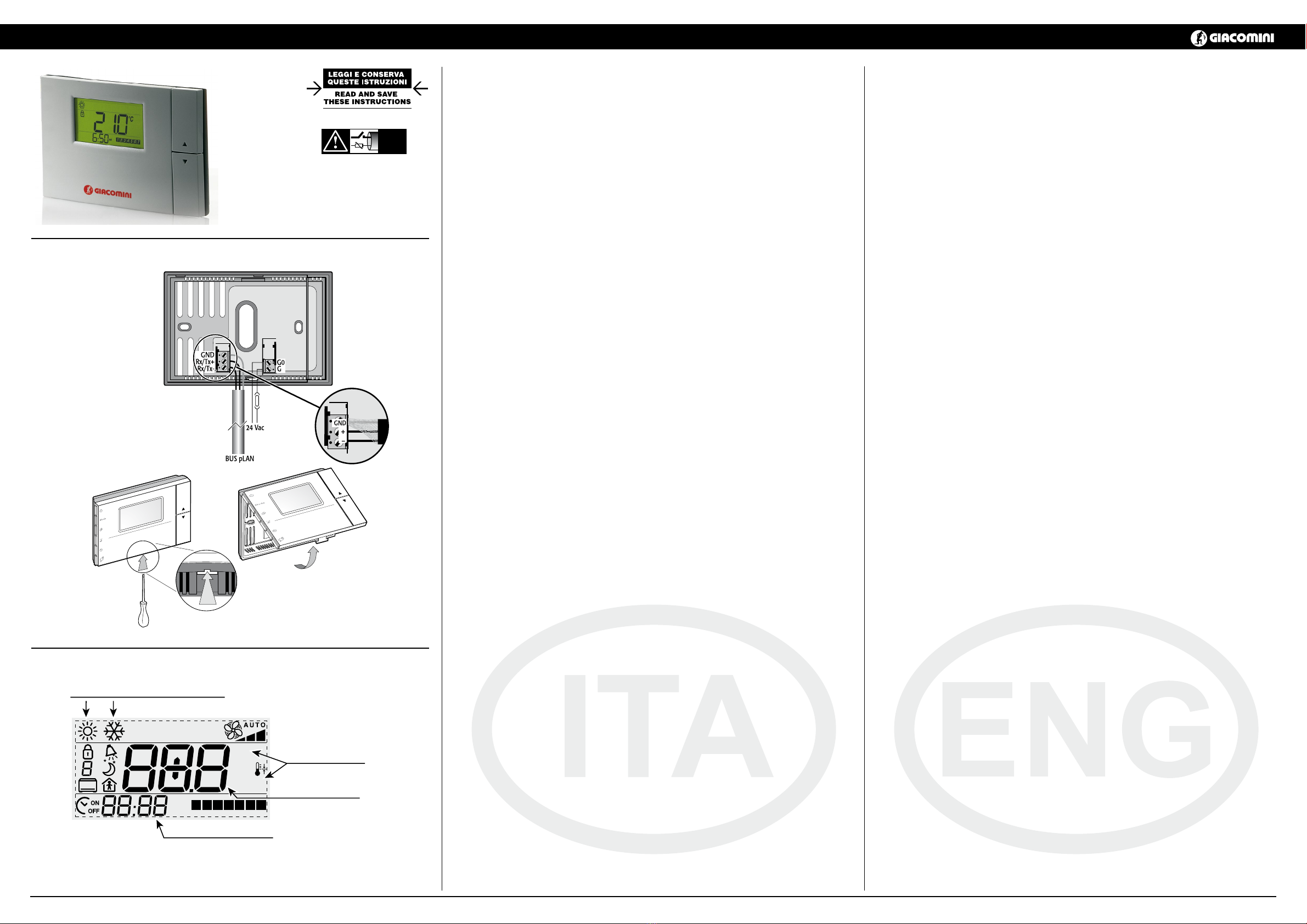
POWER
MODE
HUM
SLEEP
CLOCK
TEMP
83.5 mm
43.25 mm
Fig. 3
GIACOMINI S.p.A.
Via per Alzo 39, 28017 San Maurizio d’Opaglio (NO) Italy - www.giacomini.com
12/2018
Interfaccia utente standard
Nota: l’interfaccia utente graca può cambiare a seconda del software applicativo del controllore che ne denisce la
congurazione.
Assegnazione standard dei tasti in funzionamento normale
La tabella riportata di seguito illustra le operazioni fondamentali svolte dai tasti del dipositivo nella congurazione
standard. Le funzioni dei tasti KEY1...KEY6 dipendono dalla congurazione imposta tramite il software applicativo del
controllore.
Icona standard Nome (standard) Descrizione
KEY1 (POWER) Permette di accendere o di mettere in stand-by l’impianto
KEY6 (TEMP) Visualizza temporaneamente informazioni alternative (vedi tabella successiva)
,
UP, DOWN Impostano il set point di temperatura
Impostazione dei parametri
Per visualizzare i parametri, premere
e
no alla comparsa della scritta “par”, quindi rilasciare
mantenendo
premuto
e premere
, per 3 secondi. Selezione e modica avvengono rispettivamente con
,
,
.
Mentre il K495LY002 è connesso in pLan, qualora previsto dalla congurazione imposta dal software applicativo, la
procedura di ingresso può essere sostituita dalla pressione di uno specico tasto. Per uscire salvando le imposta-
zioni mantenere premuto
per 5 secondi.
La tabella seguente illustra il signicato dei parametri di funzionamento:
Nome Descrizione min max u.m. def.
Ad011Indirizzo di rete di K495LY002 (protocollo pLAN) 1 32 - 2
Ad021,6 Indirizzo di supervisione del K495LY002 (protocolli Modbus® e Proprietario) 1 255 - 1
Br011,2 Baudrate di rete (protocollo pLAN) 0 1 - 0
Br021,3,6 Baudrate di supervisione (protocolli Modbus® e Proprietario) 0 4 - 4
En014Abilitazione buzzer 0 1 - 1
Pc01 Calibrazione sonda ambiente -9,9 +9,9 °C /°F 0,0
Prot5,6 Protocollo seriale di comunicazione 1 3 - 1
Fr01 Indicazione release rmware - - - -
(1) Il cambiamento di valore comporta la reinizializzazione della comunicazione.
(2) “0” corrisponde a 62.500 baud, “1” corrisponde a 115.200.
(3) “0” =1200 baud, “1”=2400 baud, “2”=4800 baud, “3”=9600 baud, “4”=19.200 baud.
(4) Posto a“0”indica che la funzione buzzer è disabilitata indipendentemente dal comando del controllore. Questa funzio-
ne è signicativa soltanto se è presente l’opzione buzzer.
(5) “1” corrisponde a pLAN, “2” , “3” a ModBus.
(6) Solo nella release rmware 1.3 ed eventuali future.
Le funzioni che possono essere assegnate (da applicativo) ai tasti congurabili (KEY1...KEY6) oltre a quelle standard
descritte nella tabella precedente sono le seguenti:
Funzione Descrizione
PRG Modica dei parametri
FAN Gestione ventole
ALARM Riarmo manuale allarmi
Per una descrizione dettagliata consultare il manuale dell’applicativo utilizzato. Da applicativo è possibile gestire l’ac-
censione di tutti i simboli/indicazioni.
Caratteristiche Tecniche
• Tensione di alimentazione (secondo EN60730-1): 24 Vac ±15 %, 50/60 Hz 70 mA 1,5 VA oppure 31 Vdc ±29 % 70 mA
• Classicazione secondo UL873: Ingresso alimentazione: 24 V ac, 50-60Hz, Class 2 - 25.5 - 36.25 V dc, Class 2
Power consumption: max 1 watt
Uscite: serial link RS485, Class 2
• Condizioni di funzionamento: 0T50 °C; 10...85% U.R. non condensante;
• Condizioni di immagazzinamento: -20T70 °C; 0...85 % U.R. non condensante;
• Dimensioni (mm): vedi Fig. 3;
• Inquinamento ambientale: normale;
• Grado di Inquinamento: grado II;
• Categoria di resistenza al calore e al fuoco: A;
• Classe e struttura del software: A;
• Grado di protezione contro gli agenti atmosferici: IP30;
• Temperatura della ball pressure test sulle plastiche dell’involucro: 100 °C;
• Classicazione secondo protezione contro scosse elettriche (EN60730-1): III, da integrare in apparecchi di classe I
o II;
• Periodo sollecitazioni elettriche delle parti isolanti: lungo;
• Dispositivo di comando previsto per essere fornito a: costruttori, installatori e manutentori;
• Protezione contro i cortocircuiti: deve essere garantita dal costruttore dell’apparecchiatura in cui il K495LY002 viene
integrato o dall’installatore nale;
• Immunità contro sovratensioni: categoria 1;
• Sezione dei conduttori (mm2): da 0,5 a 1,5 mm2;
• Precisione della misura di temperatura: ±2 °C;
• Precisione della misura di umidità: ±10% U.R. (nei modelli dotati di sonda di umidità opzionale.)
Standard user interface
Note: the graphic user interface may change depending on the controller application program that denes the
conguration.
Standard assignment of the buttons in normal operation
The following table illustrates the fundamental operations carried out by the buttons on the device in the
standard conguration. The functions of buttons KEY1 to KEY6 depend on the conguration set by the controller
application program.
Standard icon Name (standard) Description
KEY1 (POWER) Used to switch the system on or to standby
KEY6 (TEMP) Temporarily displays alternative information
,
UP, DOWN Set the temperature set point
Setting the parameters
To display the parameters, press
and
until “par” is displayed, then release
while holding
and
press
, for 3 seconds. Select and modify respectively using
,
,
.
While K495LY002 is connected in pLAN, if available in the conguration set by the application program, the access
procedure may be replaced by pressing a specic button. To exit and save the settings, hold
for 5 seconds.
The table below illustrates the meaning of the operating parameters:
Name Description min max u.m. def.
Ad011K495LY002 Network address (pLAN protocol) 1 32 - 2
Ad021,6 K495LY002 supervisory address (ModBus and Proprietary protocols) 1 255 - 1
Br011,2 Network Baudrate (pLAN protocoll) 0 1 - 0
Br021,3,6 Supervisory Baudrate (ModBus and Proprietary protocols) 0 4 - 4
En014Enable buzzer 0 1 - 1
Pc01 Ambient probe calibration -9,9 +9,9 °C /°F 0,0
Prot5,6 Serial communication protocol 1 3 - 1
Fr01 Firmware release - - - -
(1) Changing the value reinitialises communication.
(2) “0” corresponds to 62,500 baud,“1”corresponds to 115,200.
(3) “0” =1200 baud, “1”=2400 baud, “2”=4800 baud, “3”=9600 baud, “4”=19.200 baud.
(4) Set to “0” indicates that the buzzer function is disabled irrespective of the controller function. This function is only valid
if the buzzer option is tted.
(5) “1” corresponds to pLAN, “2”, “3” to ModBus.
(6) Only in rmware 1.3 release and in the future.
The following functions can be assigned (by the application) to the buttons can be congured (KEY1 to KEY6), in
addition the standard functions described in the table above:
Function Description
PRG Set the parameters
FAN Fan management
ALARM Manual alarm reset
For a detailed description see the manual for the application used. The application can also manage the activation
of all the symbols/indications.
Technical specications
• Power supply (according to EN60730-1): 24 Vac ±15 %, 50/60 Hz 70 mA 1.5 VA or 31 Vdc ± 29 % 70 mA
• Classication according to UL873: Power supply input: 24 V ac, 50-60Hz, Class 2 - 25.5 - 36.25 V dc, Class 2
Power consumption, max 1 watt
Outputs: serial link RS485, Class 2
• Operating conditions: 0T50 °C; 10 to 85% rH non-condensing;
• Storage conditions: -20T70 °C; 0 to 85 % rH non-condensing;
• Dimensions (mm): see Fig. 3;
• Environmental pollution: normal;
• Degree of pollution: degree II;
• Category of resistance to heat and re: A;
• Software class and structure: A;
• Index of protection: IP30;
• Ball pressure test temperature on the plastic case: 100 °C;
• Classication according to protection against electric shock (EN60730-1): III, to be integrated into class I or II
appliances;
• Period of electrical stress across the insulating parts: long;
• Control device designed to be supplied to: manufacturers, installers and maintenance personne;
• Protection against short-circuits: must be guaranteed by the manufacturer of the appliance that the K495LY002
is integrated into or by the installer;
• Immunity against voltage surges: category 1;
• Cross-section of the wires (mm2): from 0.5 to 1.5 mm2;
• Precision of temperature measurement : ±2 °C;
• Precision of humidity measurement: ±10% rH. (in the models tted with optional humidity probe).
ATTENZIONE: separare quanto più possibile i cavi delle sonde e degli ingressi digitali dai cavi dei
carichi induttivi e di potenza per evitare possibili disturbi elettromagnetici. Non inserire mai nelle
stesse canaline (comprese quelle dei quadri elettrici) cavi di potenza e cavi di segnale.
WARNING: separate as much as possible the probe and digital input signal cables from the cables
carrying inductive loads and power cables to avoid possible electromagnetic disturbance. Never
run power cables (including the electrical panel wiring) and signal cables in the same conduits.
NO POWER
& SIGNAL
CABLES
TOGETHER
READ CAREFULLY IN THE TEXT!
Interfaccia utente / User interface
AVVERTENZE PER IL CORRETTO SMALTIMENTO DEL PRODOTTO
Questo prodotto rientra nel campo di applicazione della Direttiva 2012/19/UE riguardante la gestione dei riuti di appa-
recchiature elettriche ed elettroniche (RAEE).
L’apparecchio non deve essere eliminato con gli scarti domestici in quanto composto da diversi materiali che possono
essere riciclati presso le strutture adeguate.
Informarsi attraverso l’autorità comunale per quanto riguarda l’ubicazione delle piattaforme ecologiche atte a ricevere il prodotto
per lo smaltimento ed il suo successivo corretto riciclaggio.
Si ricorda, inoltre, che a fronte di acquisto di apparecchio equivalente, il distributore è tenuto al ritiro gratuito del prodotto da
smaltire. Il prodotto non è potenzialmente pericoloso per la salute umana e l’ambiente, ma se abbandonato nell’ambiente impatta
negativamente sull’ecosistema.
Leggere attentamente le istruzioni prima di utilizzare l’apparecchio per la prima volta.
Si raccomanda di non usare assolutamente il prodotto per un uso diverso da quello a cui è stato destinato, essendoci pericolo di
shock elettrico se usato impropriamente.
Il simbolo del bidone barrato, presente sull’etichetta posta sull’apparecchio, indica la rispondenza di tale prodotto alla normativa
relativa ai riuti di apparecchiature elettriche ed elettroniche.
L’abbandono nell’ambiente dell’apparecchiatura o lo smaltimento abusivo della stessa sono puniti dalla legge.
IMPORTANT INFORMATION FOR CORRECT DISPOSAL OF THE PRODUCT
This product falls into the scope of the Directive 2012/19/EU concerning the management of Waste Electrical and Elec-
tronic Equipment (WEEE).
This product shall not be dispose in to the domestic waste as it is made of dierent materials that have to be recycled at
the appropriate facilities.
Inquire through the municipal authority regarding the location of the ecological platforms to receive the product for
disposal and its subsequent correct recycling.
Furthermore, upon purchase of an equivalent appliance, the distributor is obliged to collect the product for disposal free of charge.
The product is not potentially dangerous for human health and the environment, but if abandoned in the environment can have
negative impact on the environment.
Read carefully the instructions before using the product for the rst time.
It is recommended that you do not use the product for any purpose rather than those for which it was intended, there being a
danger of electric shock if used improperly.
The crossed-out wheeled dustbin symbol, on the label on the product, indicates the compliance of this product with the regulations
regarding Waste Electrical and Electronic Equipment.
Abandonment in the environment or illegal disposal of the product is punishable by law.