CLOSING GATE
Gate must be
TOTALLY OPEN
to fix the grey magnet.
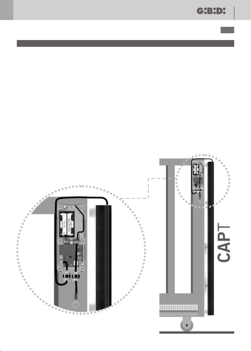
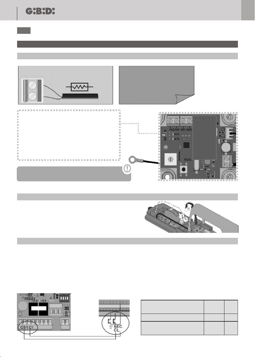
CAP ACTIVE
CAP T
CAP
MAGIN
SUPPORT
INHIBITION ZONE: NO TOUCH
30-50 CM
8 9
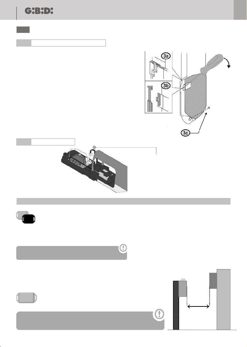
3.2.2 POSITIONING OF THE COVER
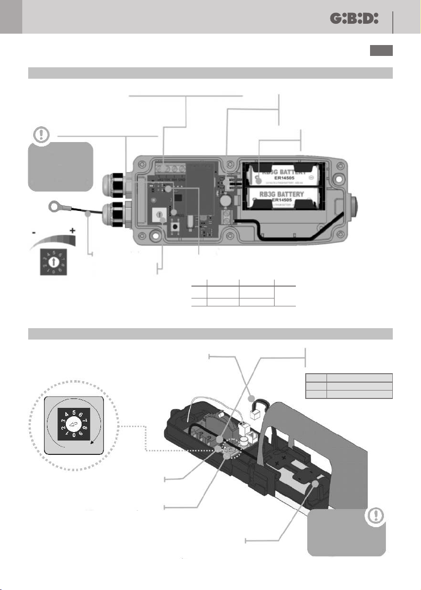
3.2.3 POWER SUPPLY
BATTERY CONNECTOR
Connect the batteries for operation.
Do not carry the equipment with
batteries connected.
3.3 - CAP MAGIN
SUPPORT
MAGIN
1-2 cm
MAGNET
GATE
MAGNETS: at the gate.
The Grey magnet should be installed to activate the NO-TOUCH sensor when the gate starts the closing movement.
The Black magnet switches off the NO-TOUCH sensor in order to allow the gate to close fully.
CAP MAGIN: install onto a support near the magnets and at the
same height
GREY – BLACK magnets position depends on the direction of the gate.
CAP MAGIN LED must be GREEN while gate is closing/opening, RED when
gate is totally closed/open.
Depending on the gate direction, BLACK magnet
is the one which de-activates the NO-TOUCH.
Before fixing the magnet, CAP ACTIVE/CAP T
must be programmed at the receiver.
The location of the black magnet indicates the
inhibition zone at closing.
In case the gate is not totally opened/closed, a safety time of 5
minutes is added to avoid battery consumption.
Maximum NO TOUCH activation time = 5 minutes
To insert the soft cap, place it in front of the support plate, taking
care to slide the flaps in their seats (3a) and the two lateral locking
hooks inside of slits arranged (3b).
Apply a light pressure so that there is a click to indicate the correct
placement of the same
Secure the cover with the screw provided.
To remove the cover reverse the procedure: remove the screw
(3c), release the cap by inserting a tool inside the slits pushing
the hooks inward.
3.3.1 FIXING THE ACTIVATION MAGNET
3.3.2 FIXING THE DEACTIVATION MAGNET
GREY
BLACK
With the GATE TOTALLY OPEN fix the south field magnet (Grey).
The Grey magnet must be 2-3 cm away from the MAGIN detector. When the gate starts closing, the Grey magnet
travels past the MAGIN and NO-TOUCH gate sensor is activated.
LED indicator on MAGIN detector changes to green color when Grey magnet passes in front of MAGIN.
With the GATE AT 30-50 cm FROM ITS CLOSED POSITION:
The Black magnet must be fixed at the other extreme of the gate (in respect of the grey magnet). The location of
this magnet depends on the inhibition zone desired.
Due to NO TOUCH detection, it is required that an INHIBITION ZONE is created at the end of the gate movement in
order to avoid the detection of the wall support by NO TOUCH detector. In this zone, the safety edge will only be
activated from normal mechanical compression.
Inhibition zone length depends on NO TOUCH sensitivity adjustment.
When NO-TOUCH sensor is detecting, an LED on the transmitter is activated. If the indicators on the transmitter
are switched off, it will be necessary to press the PROG button on the transmitter to activate, for 5 minutes,
the LED function.
The LED indicator on MAGIN detector changes to a red color when black magnet passes in front of the MAGIN.
CAPTIVE CAPTIVE
EN EN
Before fixing the black magnet, CAP ACTIVE/CAP T
must be programmed at the receiver.