Gicam WIN9 User manual

WIN9
SowareP13031Versione1.0
Manuale
Manual
Handbuch

Manualed’istallazioneed’usoManualed’istallazioneed’uso
InstallaonandusermanualInstallaonandusermanual
InstallaonsInstallaons–
–undBedienungsanleitungundBedienungsanleitung
INDICATORE
INDICATOR
ANZEIGEGERÄT
WIN9

Pagina – page – Seite 1
Indice / Table of contents / Inhaltsverzeichnis
Technical features ................................................................................................................................... 3
Symbology ............................................................................................................................................... 3
Warnings ................................................................................................................................................. 4
Identification plate of the instrument ....................................................................................................... 4
Notes ...................................................................................................................................................... 5
Mounting of the instrument ...................................................................................................................... 5
Rear panel ............................................................................................................................................... 5
Power supply of the instrument ............................................................................................................... 6
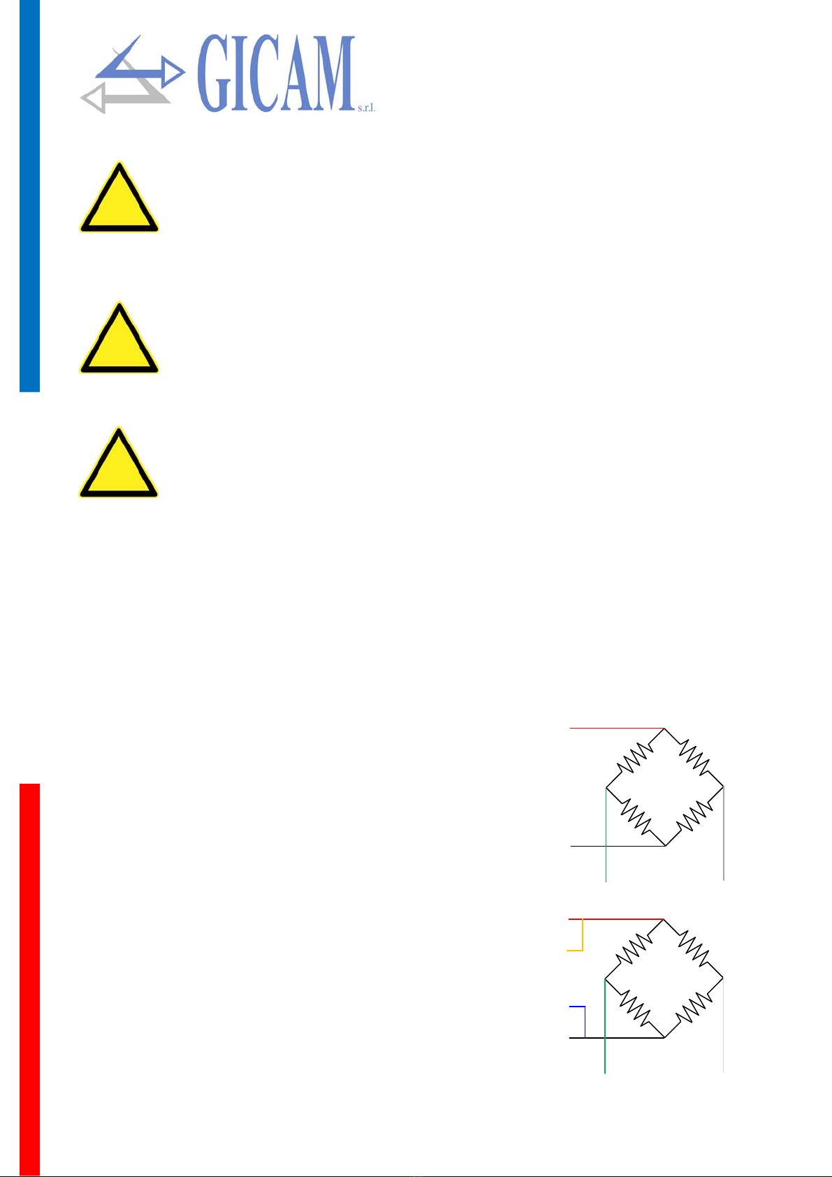
Connection of the load cell ...................................................................................................................... 6
4-wire connection ............................................................................................................................... 6
6-wire connection ............................................................................................................................... 6
Logic input connection (lower 12-pole terminal block) ............................................................................ 7
Logic output connection (lower 12-pole terminal block) .......................................................................... 7
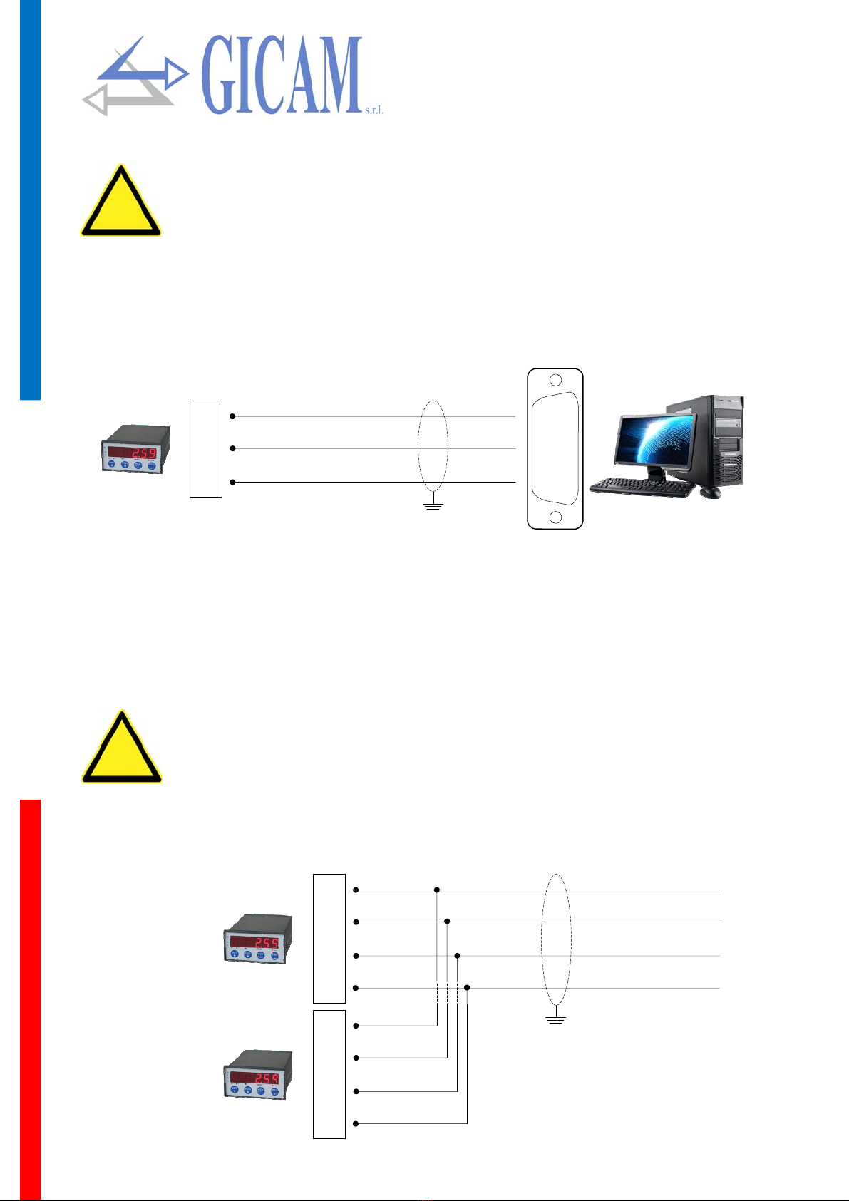
RS232 serial connection with PC (upper 12-pole terminal block) ........................................................... 8
Connection with RS422 serial line (upper 12-pole terminal block) ......................................................... 8
Connection with RS485 (upper 12-pole terminal block) .......................................................................... 9
Serial RS422 connection with repeater ................................................................................................... 9
RS422 connection with RIP60HA repeater ........................................................................................ 9
RS422 connection with RIP100HE repeater ...................................................................................... 9
Serial RS232 connection with printer .................................................................................................... 10
Serial RS232 connection with BCD card ............................................................................................... 10
Connection analog output (optional) ..................................................................................................... 11
PROFIBUS connection (optional).......................................................................................................... 11
Connection summary ............................................................................................................................ 12
Troubleshooting guide ........................................................................................................................... 12
Main operating characteristics ............................................................................................................... 13
The front panel of the instrument .......................................................................................................... 13
Display .............................................................................................................................................. 13
LED indicators .................................................................................................................................. 13
Display indications ................................................................................................................................. 14
Use of the keyboard .............................................................................................................................. 14
Keyboard lock / unlock functio ............................................................................................................... 14
Data setting ........................................................................................................................................... 15
Restore zero (semi-automatic zero) ...................................................................................................... 15
Input / output .......................................................................................................................................... 15
Dosing parameters programming .......................................................................................................... 16
Dosing operation on loading .................................................................................................................. 16
Dosing operation on discharge .............................................................................................................. 17
Dosing operation on loading without zeroing ........................................................................................ 17
Calibration data menu ........................................................................................................................... 18
Weight calibration and linearization....................................................................................................... 20
Linearization procedure .................................................................................................................... 20
Dosing program selection ...................................................................................................................... 21
Weighing parameters setting menu ...................................................................................................... 21
Logic inputs and outputs ....................................................................................................................... 23
Serial communication ports set-up ........................................................................................................ 24
Transmission frequency tables .............................................................................................................. 26
User manual .............................................................................................................................................. 13
Indice / Table of contents / Inhaltsverzeichnis ........................................................................................ 1
Installation manual ..................................................................................................................................... 3

Pagina – page – Seite 2
Analog output set-up and test menu (optional) .......................................................................................... 26
Limit values ...................................................................................................................................... 27
Serial communication protocols ............................................................................................................ 28
Continuous automatic and manual transmission protocol (demand) ............................................... 28
MODbus RTU protocol .......................................................................................................................... 28
List of supported functions ............................................................................................................... 28
Responste time of the instrument .................................................................................................... 29
Warnings .......................................................................................................................................... 29
Management of communication errors ............................................................................................ 29
Error handling of received data ........................................................................................................ 29
List holding register .......................................................................................................................... 29
Command and status register ..................................................................................................... 30
Weighing constants ..................................................................................................................... 30
Weighing parameters .................................................................................................................. 30
Serial configuration ..................................................................................................................... 30
Analog card (optional) ................................................................................................................. 30
Division value coding table .......................................................................................................... 31
SLAVE protocol ................................................................................................................................ 32
List of available commands ......................................................................................................... 32
Description of the command format ............................................................................................ 32
Characters used in the strings .................................................................................................... 32
Protocol for BCD output .............................................................................................................. 33
Protocol PROFIBUS and DeviceNet ........................................................................................... 33
Menu for quick configuration ................................................................................................................. 34
Troubleshooting guide ........................................................................................................................... 36

Pagina – page – Seite 3
Installation manual
Technical features
Logical Outputs 2 opto-isolated (clean contact) maximum 24 V DC / 60 mA each
Logical Inputs 2 opto-isolated at 24 V direct current PNP
Serial port (2 ports) RS232c/Rs422/Rs485 half duplex
Maximum cable length 15 m (Rs232c), 1000 m (Rs422 + Rs485)
Protocol serial port ASCII, Modbus
Baud rate 2400 / 9600 / 19200 / 38400 / 115000 bit/s
Program code memory 64 kbyte FLASH reprogrammable on board by RS232
Data memory 2 kbyte
Power supply 24 V cc ± 15 %
Maximum power consumption 5 W
Insulation Class II
Installation category Category II
Operating temperature - 10 °C / + 40 °C (14 °F / 104 °F)
Humidity Maximum 85% non-condensing
Storage temperature - 20 °C / + 50 °C (- 4 °F / 122 °F)
Display Numeric 6-digit, 7-segment LED (h 14 mm)
LED 5 3 mm indicator LEDs
Keyboard 4 mechanical keys
Overall dimensions 96 x 48 x 120 mm (3.78 x 1.89 x 4.72 in)
Frontal protection class IP 54
Housing material Self-extinguishing Noryl (UL94 V1)
Installation Panel mount
Cutout template 91 x 44 mm (3.58 x 1.73 in)
Wire connections Removable screw terminals
Pitch screws terminal blocks 5,08 mm
Power supply load cells 5 V dc / 90 mA (maximum 6 cells with 350 Ω in parallel) protected against short-circuit
Input sensivity ≥ 0,02 µV
Linearity < 0,01 % of full scale
Temperature deviation <0,001 % of full scale/ °C
Internal resolution 24 bit
Resolution displayed weight Up to 60,000 divisions on nominal capacity
Measuring range From -3.9 mV/V to +3.9 mV/V
Weight acquisition rate 6 Hz – 50 Hz
Digital filter 0.1 Hz – 25 Hz, selectable
Weight decimals From 0 to 3 decimals
Calibration Zero and full scale Automatic (theoretical) or executable through buttons
Compliance to norms EN61000-6-2, EN61000-6-3, EN61010-1
Tension analogue output (option) 0 – 10 V / 0 – 5 V
Current analogue output (option) 0 – 20 mA / 4 – 20 mA
Resolution 16 bit
Calibration Digital through keyboard
Impedance tension ≥ 10 kΩ
Impedance current ≤ 300 Ω
Linearity < 0,03 % of full scale
Temperature deviation <0,001 % of full scale/ °C

Pagina – page – Seite 4
Symbology
Pay particular attention to the following indications!
Warning! This operation must be carried out by specialized personnel!
!
Further information
i
Warnings
The purpose of this manual is to bring to the operator's knowledge with clarification texts and figures, the
requirements and the fundamental criteria for the installation and correct use of the instrument.
The equipment must be installed only by specialized personnel who must have read and understood
this manual. "Specialized personnel" means personnel who, due to training and professional experi-
ence, have been expressly authorized by the plant safety manager to carry out the installation of the
equipment.
Supply the instrument with voltage whose value falls within the limits specified in the characteristics.
It is the user's responsibility to ensure that the installation complies with the relevant provisions in
force.
For any anomalies found, contact the nearest service center. Any attempt of dismantling or modifica-
tion not expressly authorized will invalidate the guarantee and release the manufacturer from any re-
sponsibility.
The purchased device has been designed and produced to be used in weighing and dosing process-
Identification plate of the instrument
It is important to communicate this data in case of request for information or indications re-
garding the instrument together with the program number and version which are shown on the
cover of the manual and are displayed when the instrument is turned on.

Pagina – page – Seite 5
Notes
To clean the instrument, use a cloth slightly soaked in pure alcohol, both for the container and
for the keyboard.
During cleaning the instrument must be switched off!
Environmental pollution degree: 2
i
Mounting the instrument
The following procedures must be carried out by specialized personnel.
All connections must be made with the instrument turned off!
!
The instrument is installed in a panel in a slot with a 91 x 44 mm drilling template and is fixed by means of
Consider that the depth of the instrument, with the removable terminal blocks mounted, is
135 mm, and the space needed for connections must be reserved
Do not install the instrument near power equipment (motors, inverters, contactors, etc.) or
in any case equipment that does not comply with CE regulations for electromagnetic com-
patibility
The connection cable for the load cells must have a maximum length of 140 m/mm2
The RS232 serial line must have a length of max. 15 m (EIA RS-232-C standards)
The warnings indicated in the connection of the individual peripherals must be respected
!
Rear panel
13 14 15 16 17 18 19 20 21 22 23 24
1 2 3 4 5 6 7 8 9 10 11 12
In compliance with the regulations, the numbers of the terminal blocks have been silk-screened on the back

Pagina – page – Seite 6
Power supply of the instrument
Supply voltage: 24V cc, 5W
12-pole terminal block connection, 5.08 mm pitch
The instrument is powered through terminals 1 (+ 24 V DC) and 2 (0).
The power cable must be channeled separately from other power cables with different volt-
ages, from the load cell cables and the logic input / output cables.
!
The instrument is of insulation class II (double insulation) and the ground is not provided on
the terminals. The groudning is still necessary to connect the cable shields, therefore check
that there is a valid electrical protective grounding.
Connection of the load cell
The cell cable must not be channeled with other cables (e.g. outputs connected to remote
switches or power cables), but must follow its own path.
Any cell cable extension connections must be carefully shielded, respecting the color code
and using the cable of the type supplied by the manufacturer. The extension connections
must be made by welding, or through support terminal blocks or through the junction box
supplied separately.
The cell cable must have a number of conductors not higher than those used (4 or 6). In
the case of 6-conductor cable, of which only 4 are used (power supply and signal), connect
the reference wires to the respective polarity of the power supply wires .
!
A maximum of up to 6 350 ohm cells can be connected in parallel to the instrument. The supply voltage of
the cells is 5 V DC and is protected against temporary short circuit. The measuring range of the instrument
allows the use of load cells with sensitivity from 1 mV / V to 3.9 mV / V.
4-wire connection
19 Power supply -
20 Power supply +
21 Short circuit with terminal 20
22 Short circuit with terminal 19
23 Signal -
24 Signal +
Power supply +
Signal+
Power supply -
Signal -
Power supply +
Reference +
Reference -
Power supply -
Signal+ Signal -
6-wire connection
19 Power supply -
20 Power supply +
21 Reference +
22 Reference -
23 Signal -
24 Signal +

Pagina – page – Seite 7
Logic input connection (lower 12-pole terminal block)
The logic inputs are isolated from the instrument by optocouplers.
The logic input connection cables must not be channeled with concuctors or power cables
Use a connection cable that is as short as possible
!
To activate a logic input, it must be brought to the positive of a 24 V DC power supply while the common
must be connected to the negative of the same.
The following diagram shows two types of connection using, for example, a button on input 1 and a switch
on input 2.
16
17
18
Input 1
Input 2
Common
(pos) +
24 V CC
(neg) -
Logic output connection (lower 12-pole terminal block)
The logic outputs are electrically isolated from the instrument.
The logic outputs are photo relay with a single common. The range of each contact is 60 mA / 2 - 4 Vdc.
Each output is enabled when the contact is closed (NO contact).
The environment where the equipment is installed can normally be subject to strong magnetic
fields and electrical disturbances caused by the machines present, therefore it is good to
adopt the normal precautions to avoid that these affect the typical signals of a precision elec-
tronic equipment (filters on the remote control switches, diodes on the 24 V DC relays, etc.)
!
The connection diagram of the outputs is shown below:
13
14
15
Contact output 1
Contact output 2
Common

Pagina – page – Seite 8
RS232 serial connection with PC (upper 12-pole terminal block)
To make the serial connection use a shielded cable, taking care to connect the shield to
one of the two ends to ground. If the cable has a greater number of conductors than those
used, connect the free conductors to the ground
The serial connection cable must have a maximum length of 15 m (EIA RS-232-C stand-
ards), beyond which you must use the RS422 interface equipped in the instrument
The cable must not be channeled with other cables (e.g. outputs connected to remote
switches or power cables), but must possibly follow its own path
!
The connection diagram with 9-pole PC connector is shown below:
6
8
7
Data transmission
Data reception
Signal ground
2
3
5
Connection with RS422 serial line (upper 12-pole terminal block)
Serial connections can be made for long distances via the RS422 / RS485 serial interface. This type of con-
nection also allows you to connect multiple instruments to a MASTER unit (personal computer, PLC etc.),
using a single serial line and therefore only one MASTER serial port. The maximum number of connected
instruments is 32. Obviously, the master unit must also be equipped with an RS485 or RS422 serial inter-
face, otherwise it can be supplied as an option.
The serial connection cable must be of the type suitable for RS422 / RS485 serial commu-
nications with 2 inverted pairs of conductors (twisted pair) for RS422 or 1 always inverted
pair for RS485 and its shielding.
The cable must not be channeled with other cables (e.g. outputs connected to remote
switches or power cables), but must possibly follow its own path.
!
9
11
10
12
TXD +
TXD -
RXD+
RXD -
TXD +
TXD -
RXD+
RXD -
upper 12-pole terminal block RS422 line
9
11
10
12
TXD +
TXD -
RXD+
RXD -
Other instrument

Pagina – page – Seite 9
Connection with RS485 serial line (upper 12-pole terminal block)
9
11
10
12
TXD +
TXD -
RXD+
RXD -
TXD + / RDX +
TXD - / RXD -
upper 12-pole terminal block RS485 line (2 wire)
9
11
10
12
TXD +
TXD -
RXD+
RXD -
Other instrument
Serial RS422 connection with repeater
In the case of a repeater connection, a single inverted pair of transmission wires is suffi-
cient (TX +, TX -).
The cable must not be channeled with other cables (e.g. outputs connected to remote
switches or power cables), but must possibly follow its own path.
!
RS422 connection with RIP60HA repeater
9
10
Data transmission
Data reception
9
1
7
RS422 connection with RIP100HE repeater
9
10
Data transmission
Data reception

Pagina – page – Seite 10
Serial RS232 connection with printer
The printer must be equipped with the RS232 serial interface. The printer must be configured to receive
data from the serial interface (instead of the parallel one) and the following specifications must be set:
Velocity: 9600 bps (or other selection according to the speed selected on the instrument).
String length: 8 bit.
Start bit: 1 bit. Parity bit: 0 bit. Stop bit: 1 bit.
Handshaking: DTR protocol.
6
8
Data transmission
Signal ground
3
7
Refer to the printer manual to make your selections
To make the serial connection use a shielded cable, taking care to connect the shield to
ground at only one of the two ends. If the cable has a greater number of conductors than
those used, connect the free conductors to the shield.
Normally, the serial interface connector of the printer is of the 25 pole female type, so a 25
pole male connector must be wired to the connection cable.
!
The length of the serial connection cable must not exceed 15 meters (EIA RS-232-C standards). Beyond
this measure, the RS422 serial interface with which the instrument can be optionally equipped must be
adopted.
Serial RS232 connection with BCD card
6
8
Data transmission
Signal grould
3
5
To make the serial connection use a shielded cable, taking care to connect the shield to
ground at only one of the two ends. If the cable has a greater number of conductors than
those used, connect the free conductors to the shield.
The serial connection cable must have a maximum length of 3 meters. The cable must not
be channeled with other cables, but must possibly follow its own path.
!

Pagina – page – Seite 11
Connection analog output (optional)
The instrument, when in this hardware configuration, provides an optically isolated analog current and volt-
age output.
Characteristics:
Analog voltage output: range from 0 to 10 Volts or from 0 to 5 Volts, minimum load 10KΩ
Analog current output: range from 0 to 20 mA or from 4 to 20 mA. The maximum load is 300Ω .
The settings for the type of analog output provided (voltage or current) is determined at the factory and
must be specified at the time of purchase.
To make the connection, use a shielded cable, taking care to connect the shield to ground
at only one of the two ends.
The analog transmission is particularly sensitive to electromagnetic disturbances therefore
!
Current +
Tension +
Common -
3
5
4
Analog output
To make the connection use a ProfiBus cable
For connection, the HMS_1810.GSD file must be present on the PLC / PL (supplied with
the instrument)
!
PROFIBUS connection (optional)
The instrument, when in this hardware configuration, has a PROFIBUS DP fieldbus connector at the top.
PROFIBUS baudrate from 9.6 kbps to 12 Mbps
3
4
5
6
8
B-Line
RTS
GND Bus
+5 V Bus
A-Line
ProfiBus cable
If the PROFIBUS connection is present, there can be no analogue output!
i

Pagina – page – Seite 12
Connection summary
The following is a summary of the connections to be made in the terminal blocks:
13 14 15 16 17 18 19 20 21 22 23 24
1 2 3 4 5 6 7 8 9 10 11 12
Number 12-pole terminal block (1-12)
1 Power supply 24VCC +
2 Power supply 24VCC -
3 Analog output in current
4 Analog output in tension
5 Common analog outputs
6 RS232 Tx
7 RS232 Rx
8 Signal ground
9 RS422 Tx +
10 RS422 Tx -
11 RS422 Rx +
12 RS422 Rx -
Number 12-pole terminal block (13-24)
13 Output 1
14 Output 2
15 Common outputs
16 Input 1
17 Input 2
18 Common inputs
19 Power supply load cells -
20 Power supply load cells +
21 Reference load cells +
22 Reference load cells -
23 Signal load cells -
24 Signal load cells +
Troubleshooting guide
Problem Possible cause Remedy
The instrument remains
switched off
The supply voltage is not the one required Provide the correct supply voltage
The weight display re-
mains blocked
The load cell is not functioning properly or
has not been connected correctly
Make sure with a tester that you
have 5V between + and - power
and between + and - reference
and check the movement in milli-
volts between + and - signal when
you load or unload the cell
The inputs and / or out-
puts are not working
properly
Wiring or software setting errors Use the I / O Test function to verify
the correct operation of inputs and
outputs and to check the settings
of the specific program

Pagina – page – Seite 13
User manual
Main operating characteristics
The main operating characteristics are:
The control of 2 programmable weight thresholds.
The serial connection Rs232, USB (in parallel with Rs232), Rs422 or Rs485 with other devices (PC,
weight repeaters, printer, etc.) to transmit weight values and receive settings.
The control of the maximum weight value reached (peak).
System configuration includes the following optional installations (only one can be installed)
Analogue voltage or current output.
Connection to fieldbus Profibus , DeviceNet or CanOpen
The front panel of the instrument
Display
The weight of the scale is normally shown on the 6-digit display. Based on the various programming proce-
dures, the display is used for programming the parameters to be entered in the memory, i.e. messages that
indicate the type of operation in progress and are therefore an aid to the operator in managing and pro-
gramming the instrument.
LED indicators
Below the display there are 5 LED indicators:
1 Logic output 1 status (on = contact closed, off = contact open)
2 Logic output 2 status (on = contact closed, off = contact open)
F An autotare was performed
NET The displayed value is the net weight
Indicates the stable weight condition

Pagina – page – Seite 14
Display indications
P13031
When the instrument is switched on, the display test is performed, then a software iden-
tification code appears and then the relative version.
It is important to communicate these codes in case of request for assistance.
When a programming procedure is not in progress, the display shows the detected weight expressed in kg.
______
Overload warning
When the gross weight on the scale exceeds the maximum capacity of the weighing sys-
tem by more than 9 divisions, the display shows this message.
0-L Weight signal absent or outside reading range
Use of the keyboard
The instrument is programmed and controlled through the keyboard consisting of 4 keys, all with double
function. The selection of one of the two key functions is automatically established by the instrument based
on the operation in progress.
In general, the programming menus are managed using the and keys to scroll through the items,
the key to access teh relevant submenu or programmable parameter, while the key leaves the
menu or returns to the superior level.
Key Function
Access to the set points programming menu
Display indication selection (gross weight, net weight)
(Long press) Weight / peak display selection
Display value reset (gross weight, net weight or peak)
Send weight string on serial line
(Long press) Access to the quick setup menu
+
(Long press) Access to the setup menu
Keyboard lock / unlock function
LocK
Exit
or
Keyboard locked
unloCK
Exit
Keyboard unlocked
Keep
pressed
5 sec.

Pagina – page – Seite 15
Data setting
Restore zero (semi-automatic zero)
This operation is performed to correct small zero movements of the scale. To carry out the zeroing function,
it is necessary to switch the display to the gross weight indication (NET LED off).
The gross weight reset command is not performed in the following conditions:
Weight instable (the weight does not stabilize within 3 seconds from the reset command)
Gross weight, compared to the original zero calibration, greater (positive or negative) than the value
of the parameter entered in divisions (from 0 to 200) in the menu item 0 bAnd from the PArAM menu
(if this parameter is 0, the function is disabled).
Input / Output
Input
1 Start dosing
2 Stop dosing
1 Quick dosing
2 Slow dosing
Output
123456
Confirm value
Select next digit
Increase digit
Decrease digit
Restores zero scale on gross weight

Pagina – page – Seite 16
Dosing parameters programming
The set, preset and tail values are compared with the weight to drive the logic outputs and then per-
form the dosage. Dosage operation is explained on the next page.
During the dosing parameter setting phase, all the outputs are deactivated.
Dosing operation on loading
The tool allows to dose a product with two extraction speeds by performing the autotare at each cycle start.
Close the START contact or press the FUN key to start the dosage:
If the SET load value previously set is zero, the message noSEt will be displayed for 3 seconds and the
dosage will not start.
When the net weight reaches the SET—CODA value, the output 2 SLOW loading output is opened, the
weight stabilization will be waited for and after 3 seconds, the autotare will be cancelled and the weight pre-
sent on the scale ill be displayed.
If the full scale of the system is exceeded, the dosage will be stopped.
During the dosage, the letter D will appear on the left of the display and the net weight. When the net
weight reaches the SET - PRESET value, the FAST load output 1 will be opened.
To stop the dosage at any time, close the STOP input or press the FUN key. At the start the autotare of the
weight present in the scale is performed, the instrument automatically switches to the net weight display
and the two outputs of SLOW load and FAST load are closed simultaneously.
If the SET load value added to the gross weight is greater than the maximum weight set, the message
oVEr will be displayed for 3 seconds and the dosage will not start.
If the SET load value is lower than the COdA the ErCodA message will be displayed for 3 seconds and
the dosage will not start.
SEt Set value Exit menu
PrESEt Set value
CodA Set value
Exit menu

Pagina – page – Seite 17
Dosing operation on discharge
When the unloaded net weight reaches the SET - PRESET value, the FAST unloading output 1 will be
opened. When the unloaded net weight reaches the SET - TAIL value, the SLOW unloading outlet 2 will be
opened, the stable weight will be waited for and after 3 seconds, the autotare will be canceled and the
weight present on the scale will be displayed. If the full scale of the system is exceeded, the dosage is inter-
rupted.
Dosing operation at loading without zeroing
The instrument allows to dose a product with two extraction speeds. Close the START contact or press the
FUN key to start the dosage:
If the full scale of the system is exceeded, the dosage is interrupted.
During the dosage, the letter D will appear on the left of the display and the gross weight. When the net
weight reaches the SET - PRESET value, the FAST load output 1 will be opened. When the net weight
reaches the SET - TAIL value, the SLOW loading output 2 will be opened, the stable weight will be waited
for and after 3 seconds the weight present on the scale will be displayed without the letter D.
To stop the dosage at any time, close the STOP input or press the FUN key. At start the two outputs of
SLOW load and FAST load are closed simultaneously.
If the SET load value added to the gross weight is greater than the maximum weight set, the message
OVEr will be displayed for 3 seconds and the dosage will not start.
If the SET load value is lower than the CODA, the ErCodA message will be displayed for 3 seconds and the
dosage will not start.
If the SET load value previously set is zero, the message noSEt will be displayed for 3 seconds and the
dosage will not start.
The tool allows you to dose a product with two extraction speeds by performing the autotare at each cycle
start. Close the START contact or press the FUN key to start the dosage:
If the SET discharge value previously set is zero, the message noSEt will be displayed for 3 seconds and
the dosage will not start.
If the SET discharge value is lower than the CODA, the ErCodA message will be displayed for 3 seconds
and the dosage will not start.
If the SET discharge value is greater than the gross weight on the scale at start, the message noProd is
displayed for 3 seconds and the dosage does not start.
To stop the dosage at any time, close the STOP input or press the FUN key.
At the start the autotare of the weight present in the scale is performed, the instrument automatically switch-
es to the net weight display and the two outputs of SLOW load and FAST load are closed simultaneously.
During the dosage, the letter D will appear on the left of the display and the net weight.

Pagina – page – Seite 18
Calibration data menu
CAPAC Set value
nEt Set value
SEnSit Set value
dEAd L Set value
SiGnAl Set value
dSPdiV d0.001 d 50
CountS Set value
Keep
pressed
3 sec.
ConFiG CAlibr ProGr PArAM in-out SEriAl AnAloG
StorE
Exit menu
Table of contents
Other Gicam Measuring Instrument manuals