MFR120 Series 13.56MHz RFID Reader
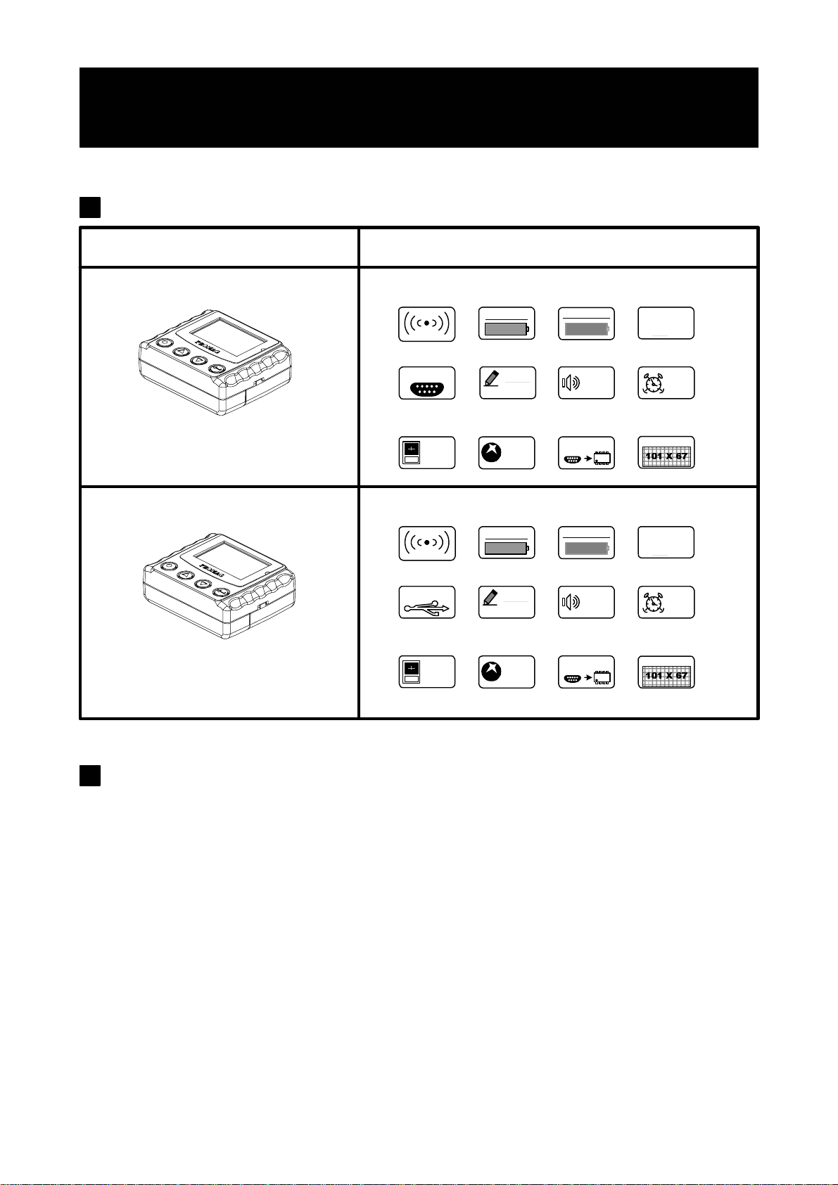
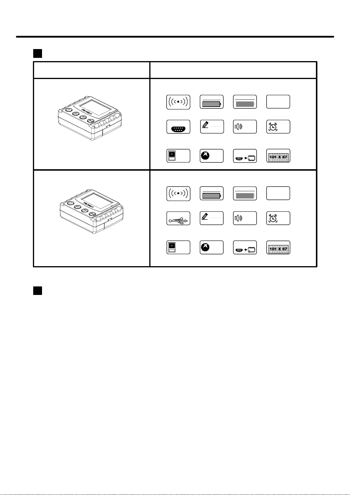
MFR120
RS232 Interface
MACHINE TYPE FUNCTION
GET
VER1.2
N
F-MEM
512 KB
OFF
AUTO
OFF
RTC
RS-232
1. Insert batteries into your device properly, with the (+) and (-) terminals aligned correctly.
2. Discharged batteries should be removed from equipment to prevent possible damage.
3. Store the batteries in a cool and dry place. [Batteries should be stored at temperatures between 50°F (10°C) and 77°F
(25°C), with relative humidity not exceeding 65 percent. Refrigeration of alkaline batteries is not necessary because
of their very good capacity retention. Excessive temperature cycling and storage at temperatures greater than 77°F
(25°C) should be avoided to maximize shelf life.]
4. Remove batteries from the electrical device if the device is not going to be used for a long time.
5. Keep battery contact surfaces and battery compartment contacts clean by rubbing them with a clean pencil eraser or
a rough cloth each time you replace batteries.
6. Keep batteries away from children. If swallowed, contact a physician at once.
7. Don't recharge a battery unless it is specifically marked "rechargeable". Attempts to recharge an alkaline battery
may cause an imbalance within the cell, leading to gassing and possibly explosion on either charge or discharge
cycles.
8. Don't dispose of batteries in a fire—they may rupture or leak.
9. Don't carry loose batteries in a pocket or purse with metal objects like coins, paper clips, etc. This will short-circuit
the battery, generating high heat.
Read the instructions on your device before installing
batteries
FMM
MFR120U
USB Interface
GET
VER1.2
N
F-MEM
512 KB
OFF
AUTO
OFF
RTC
FMM
USBVer 1.1
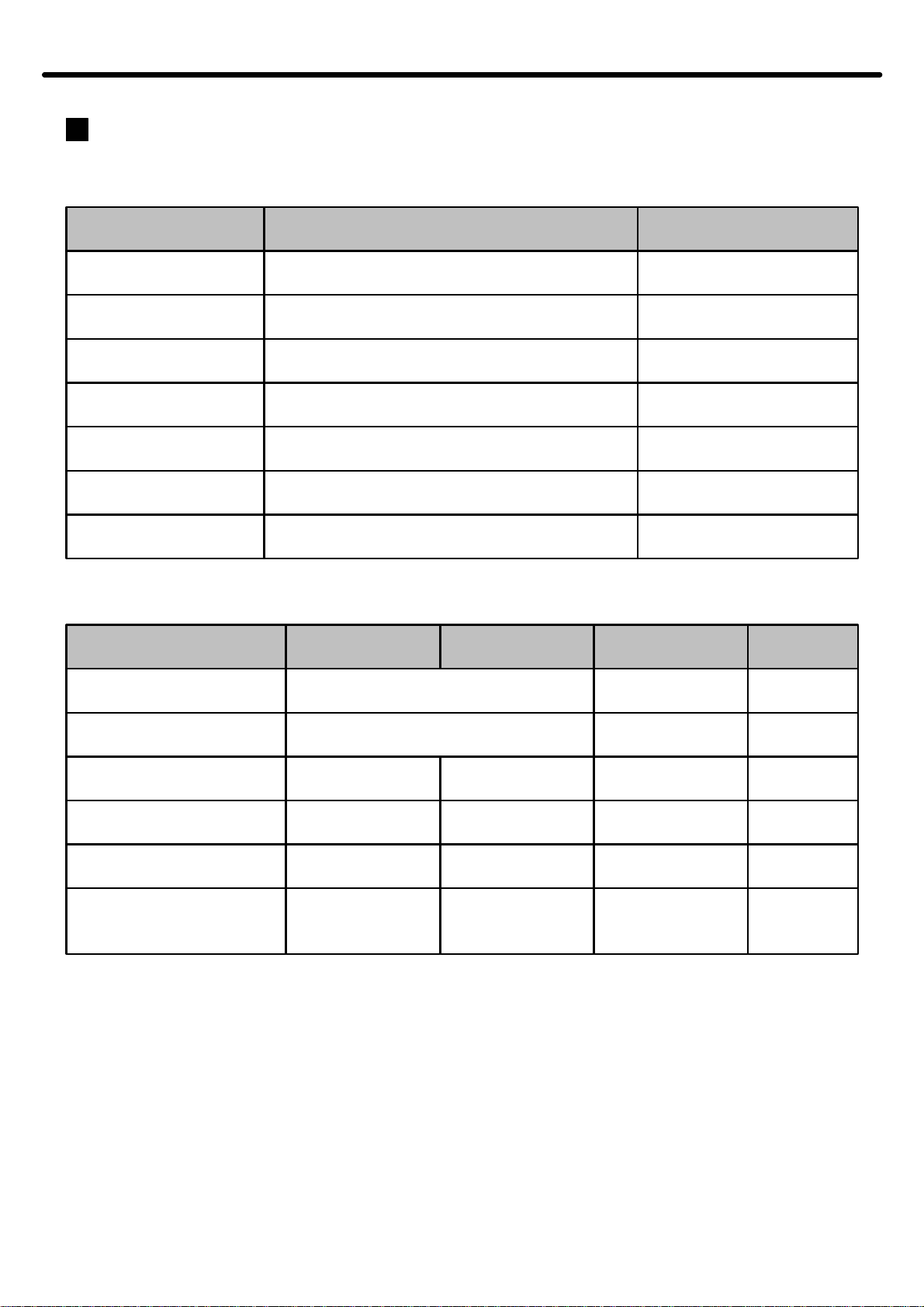
Muti-Battery
Single Cell NiHM / NiCd
ALKALINE
LR03 / AAA
BEEP
BEEP
LCD
LCD
Muti-Battery
Single Cell NiHM / NiCd
ALKALINE
LR03 / AAA
REC QUEUE
REC QUEUE
13.56M
13.56M
8192
8192
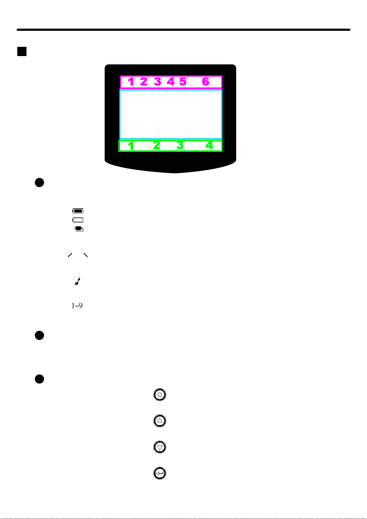
Information
5