Giga-tronics 3000-4353 User manual

Manual07504353 Model3000‐4353
Model3000‐4353
32SPSTSwitchModule
90401310
Page1
OperationManual

Manual07504353 Model3000‐4353
Alltechnicaldataandspecificationsinthispublicationaresubjecttochangewithoutpriornoticeanddo
notrepresentacommitmentonthepartofGiga‐tronics,Incorporated.
©2011Giga‐tronicsIncorporated.Allrightsreserved.PrintedintheU.S.A.
Giga‐tronicsSeries3000SwitchingModulesarewarrantedagainst
defectivematerialsandworkmanshipforthreeyearsfromdateofshipment,
orasdetailedinthewarrantysectionofthismanual.Giga‐tronicswill,atits
option,repairorreplaceproductsthatareprovendefectiveduringthe
warrantyperiod.ThiswarrantyDOESNOTcoverdamageresultingfrom
improperuse,norworkmanshipotherthanGiga‐tronicsservice.Thereisno
impliedwarrantyoffitnessforaparticularpurpose,norisGiga‐tronicsliable
foranyconsequentialdamages.Specificationandpricechangeprivilegesare
reservedbyGiga‐tronics.
Warranty
CONTACTINFORMATION
Giga‐tronics,Incorporated
4650NorrisCanyonRoad
SanRamon,California94583
Telephone: 800.726.4442(onlywithintheUnitedStates)
925.328.4650
Fax:925.328.4700
OntheInternet:www.gigatronics.com
Page2
OperationManual

Manual07504353 Model3000‐4353
Page3
OperationManual
Regulatory compliance information
This product complies with the essential requirements of the following applicable European
Directives, and carries the CE mark accordingly.
89/336/EEC and 73/23/EEC EMC Directive and Low Voltage Directive
EN61010-1 (1993) Electrical Safety
EN61326-1 (1997) EMC – Emissions and Immunity
Manufacturer’s Name: Manufacturer’s Address
Giga-tronics, Incorporated 4650 Norris Canyon Road
San Ramon, California 94583
U.S.A.
Type of Equipment: Model Series Number
Switching Module 3000-4353
DeclarationofConformityonfile.ContactGiga‐tronicsatthefollowing;
Giga‐tronics,Incorporated
4650NorrisCanyonRoad
SanRamon,California94583
Telephone: 800.726.4442(onlywithintheUnitedStates)
925.328.4650
Fax:925.328.4700

Manual07504353 Model3000‐4353
Page4
OperationManual
Record of Changes to This Manual
Use the table below to maintain a permanent record of changes to this document. Corrected
replacement pages are issued as Technical Publication Change Instructions (TPCI). When you
are issued a TPCI, do the following:
1. Insert the TPCI at the front of the manual binder.
2. Remove the pages from the manual binder that are noted in the TPCI.
3. Replace the page(s) removed in the previous step with the corrected page(s).
4. Record the changes in the table below.
TPCI
Number TPCI Issue
Date Date Entered Comments

Manual07504353 Model3000‐4353
Page5
OperationManual
Revision History
Revision Description of Change Chg Order # Approved By
Initial Release
A Updated 6/02
B Updated 2/08
C Reformatted 3/12 RCW

Manual07504353 Model3000‐4353
Page6
OperationManual
Contents
Contents........................................................................................................................................................6
Chapter1Introduction.................................................................................................................................7
1.1SafetyandManualConventions.........................................................................................................7
1.1.1ProductReference.......................................................................................................................7
1.1.2PersonalSafetyAlert...................................................................................................................7
1.1.3EquipmentSafetyAlert...............................................................................................................7
1.1.4Notes...........................................................................................................................................7
1.1.5ElectricalSafetyPrecautions.......................................................................................................7
Chapter2ConfigurationTable......................................................................................................................8
Chapter3FunctionalDescription.................................................................................................................9
3.1Introduction........................................................................................................................................9
3.2GeneralDescription............................................................................................................................9
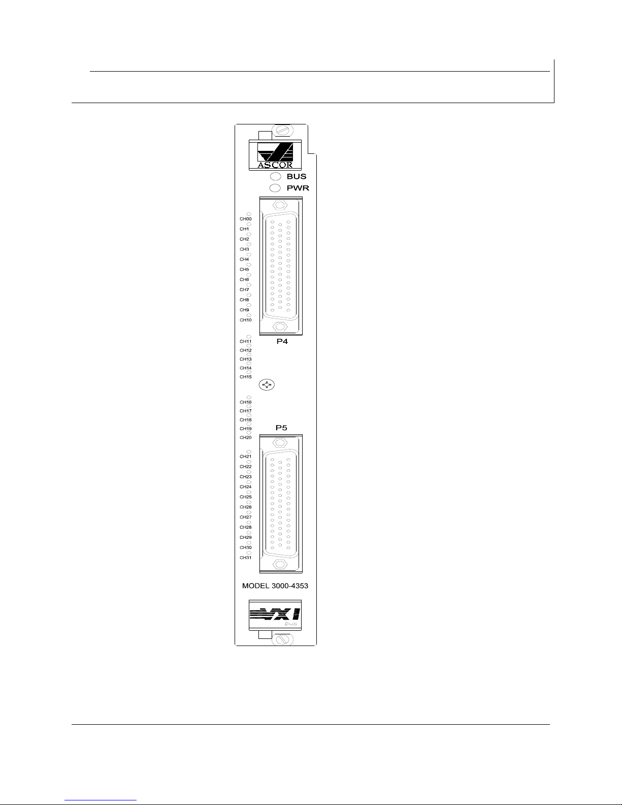
Chapter4FrontPanel.................................................................................................................................10
Chapter5ControlsandIndicators..............................................................................................................11
5.1VXILogicalAddress...........................................................................................................................11
5.2LEDs..................................................................................................................................................11
5.2.1“BUS”LED..................................................................................................................................11
5.2.2“PWR”LED.................................................................................................................................11
Chapter6InternalSettings.........................................................................................................................12
6.1Fuse...................................................................................................................................................12
6.2J105...................................................................................................................................................12
6.3J107......................................................................................................Error!Bookmarknotdefined.
6.4J106......................................................................................................Error!Bookmarknotdefined.
6.5VXIbusInterruptLevelSelection.........................................................................................................12
Chapter7Specifications.............................................................................................................................13
Chapter8RegisterMap..............................................................................................................................15
Chapter9FrontPanelPinList.....................................................................................................................16

Manual07504353 Model3000‐4353
Chapter1 Introduction
1.1 SafetyandManualConventions
Thismanualcontainsconventionsregardingsafetyandequipmentusageasdescribedbelow.
1.1.1 ProductReference
Throughoutthismanual,theterm“CommonCoreSwitchingPlatform,Series8800”referstoallmodels
ofwithintheseries,unlessotherwisespecified.
1.1.2 PersonalSafetyAlert
WARNING:Indicatesahazardoussituationwhich,ifnotavoided,couldresultin
deathorseriousinjury.
WARNING
!
1.1.3 EquipmentSafetyAlert
CAUTION:Indicatesasituationwhichcandamageoradverselyaffecttheproductor
associatedequipment.
CAUTION
1.1.4 Notes
Notesaredenotedandusedasfollows:
NOTE:Highlightsoramplifiesanessentialoperatingormaintenanceprocedure,practice,conditionor
statement.
1.1.5 ElectricalSafetyPrecautions
Anyservicinginstructionsareforusebyservice‐trainedpersonnelonly.Toavoidpersonalinjury,donot
performanyserviceunlessyouarequalifiedtodoso.
Forcontinuedprotectionsagainstfirehazard,replacetheAClinefuseonlywithafuseofthesame
currentratingandtype.Donotuserepairedfusesorshortcircuitedfuseholders.
Page7
OperationManual

Manual07504353 Model3000‐4353
Page8
OperationManual
Chapter2 ConfigurationTable
TOPASSEMBLY
PL90401310
ASM90401310
PL85003950‐001
ASM85003950‐001
SCH85003950‐001
PL=PARTSLIST,ASM=ASSEMBLYDRAWING,SCH=SCHEMATIC.

Manual07504353 Model3000‐4353
Page9
OperationManual
Chapter3 FunctionalDescription
3.1 Introduction
TheASCORVXI3000‐4353consistsof32SinglePoleSingleThrow(SPST)relays.Thismodulecanbeused
asadirectinterchangefortheTektronixVXImoduleVX4353.Eachrelayisindependentlycontrolledand
canbeindependentlyopenedorclosedunderprogramcontrol.
3.2 GeneralDescription
The3000‐4353isadirecthardwarereplacementfortheTektronixVX4353.Thesamefrontpanel
connectors,thesamesignalscometothesamepins,andthespecificationsarethesameorbetter.No
specialcablesoradapterarenecessary.ASCORalsoprovidesasoftwaredriverwhichwillrunboththe
VX4353andthe3000‐4353.

Manual07504353 Model3000‐4353
Chapter4 FrontPanel
Page10
OperationManual

Manual07504353 Model3000‐4353
Chapter5 ControlsandIndicators
ThefollowingcontrolsandindicatorsareprovidedtoselectanddisplaythefunctionsoftheASCOR
3000‐4353Module’soperatingenvironment.
5.1 VXILogicalAddress
TheLogicalAddressSwitchisdualcircularswitches,D1andD2whicharelocatedattherearofthe
module.Theaddresscanbesettoanyvaluebetween1and255(decimal)or1andFF(hexadecimal),
(address0isreservedfortheresourcemanager).However,theModulefullysupportsDynamic
ConfigurationasdefinedinSectionFoftheVXIspecification,address255(FF)shouldbeselectedonlyif
theResourceManageralsosupportsDynamicConfiguration.
5.2 LEDs
ThefollowingLEDsarevisibleattheModule’sfrontpaneltoindicatethe
statusofthemodule’soperation:
5.2.1 “BUS”LED
ThisgreencolorLEDisnormallyoffandwillflashonwhenthemoduleisaddressedbythesystem.
5.2.2 “PWR”LED
ThisredcolorLEDisnormallyonwhentheModuleisPoweredup.
Page11
OperationManual

Manual07504353 Model3000‐4353
Page12
OperationManual
Chapter6 InternalSettings
Thefollowingitemsareinsidethemoduleandcanbereachedbyremovingthesidecover.
6.1 Fuse
TheASCORVXI3000‐4353usesa5Ampfuseinthe+5Voltlineanda5Afuseinthe+12Voltline.Ifany
fuseopens,removethefaultbeforereplacingthefusetoavoidanyotherdamage.
6.2 VXIbusInterruptLevelSelection
TheVXIbusinterruptlevelissetwiththreebitsinthe“3Eh”register.
Seethesectionon“A16ADDRESSSPACEREGISTERDESCRIPTION”.
Theinterruptlevelisfactorysetto“nointerrupt”.

Manual07504353 Model3000‐4353
Page13
OperationManual
Chapter7 Specifications
Configuration:32SPSTindividualrelays.
RelayType:AromatJQ1AE‐12V
ContactRatings:SwitchingCurrent(MAX)=5A
SwitchingVoltage(MAX)=277VAC,110VDC
SwitchingPower(MAX)=1250VA
MaximumoperatingSpeed: 100operationspersecond
ProgrammableRelayDelay: 0to65535milliseconds.
OperationalLife:2X10e5
DutyCycle:Continuous
Dwell:Recommendeddwelltimeatmaximumswitching
rateis4millisecondsminimum.
SignalPathSpecifications:Signalpathresistance
Initial:<0.3oHMS
Insulationresistance:>10Gigaohms
Isolation
WipertoOpenContact: <‐18dBat1MHz
CrosstalkbetweenChannels: <‐40dBat1MHz
PowerupCondition:Atpowerupallrelaysarereset(Open)
OperationalLife:5X10e6
VXICompatibility:FullycompatiblewithVXISpecificationREV.1.0.
VXIDeviceType:VXIregisterbasedwithASCORdriver.
VXICardSize:Csize,oneslotwide.
Temperature:0°Cto+50°C,operating
‐40°Cto+85°C,storage
Humidity<95%R.H.,non‐condensing,0°Cto+30°C.
<75%R.H.,non‐condensing,+31°Cto+40°C
<45%R.H.,non‐condensing,+41°Cto+50°C

Manual07504353 Model3000‐4353
Page14
OperationManual
VXIBusRadiatedEmissions: ComplieswithVXIbusSpecification
VXIBusConductedEmissions:ComplieswithVXIbusSpecification.
Dimensions:VXICsize;10.3inx13.8inx1.2in
Weight:3lbs.
FrontPanelConnectors: 50PositionPCMount
Tyco(AMP)206971‐2

Manual07504353 Model3000‐4353
Page15
OperationManual
Chapter8 RegisterMap
A16 Address Space Register Description
Offset Value
00h CFB5 hex
C = Register based, A16/A24
FB5 = ASCOR Manufacturer ID
02h 7F2C hex
7 = 10,000 hex space in the A24 Address space
F2C = HV Discrete Driver/Receiver VXI Module number
04h FFFC hex (typical after running Resource Manager)
In order to reset the module: read this address, set bit 0 high, then set
bit 0 low without altering the other bits.
Control Bit
3Eh 0 Low true output enable to the coil driver ICs.
1 When low enables read back of the coil state.
When high enables read back of the data registers.
2 Leave set to 0, reserved by Ascor.
3 Interrupt bit 0 (LSB) Used to set the Module IRQ Level:
4 Interrupt bit 1 0 = No Interrupts
5 Interrupt bit 2 (MSB) 1-7 = IRQ1-IRQ7
6-7 Don’t Care.
8-15 Mask Off.

Manual07504353 Model3000‐4353
Page16
OperationManual
REGISTER=8000h
REGISTERREGISTER
8000h8000h
RELAY16BIT32BIT
K100
K211
K322
K433
K544
K655
K766
K877
K988
K1099
K111010
K121111
K131212
K141313
K151414
K161515
REGISTERREGISTER
8002h8000h
RELAY16BIT32BIT
K17016
K18117
K19218
K20319
K21420
K22521
K23622
K24723
K25824
K26925
K271026
K281127
K291228
K301329
K311430
K321531

Manual07504353 Model3000‐4353
Page17
OperationManual
Chapter9 FrontPanelPinList
RELAYCOMMON
CONTACT
NORMALLYOPEN
CONTACT
K1P4‐2P4‐1
K2P4‐4P4‐3
K3P4‐6P4‐5
K4P4‐8P4‐7
K5P4‐10P4‐9
K6P4‐12P4‐11
K7P4‐14P4‐13
K8P4‐16P4‐15
K9P4‐19P4‐18
K10P4‐21P4‐20
K11P4‐23P4‐22
K12P4‐25P4‐24
K13P4‐27P4‐26
K14P4‐29P4‐28
K15P4‐31P4‐30
K16P4‐33P4‐32
K17P5‐2P5‐1
K18P5‐4P5‐3
K19P5‐6P5‐5
K20P5‐8P5‐7
K21P5‐10P5‐9
K22P5‐12P5‐11
K23P5‐14P5‐13
K24P5‐16P5‐15
K25P5‐19P5‐18
K26P5‐21P5‐20
K27P5‐23P5‐22
K28P5‐25P5‐24
K29P5‐27P5‐26
K30P5‐29P5‐28
K31P5‐31P5‐30
K32P5‐33P5‐32
P4‐17,50=AGND
P5‐17,50=AGND
NOTE:P4=J1,ANDP5=J2ONSCHEMATIC
Table of contents
Other Giga-tronics Switch manuals
Popular Switch manuals by other brands

Ubiquiti
Ubiquiti UniFi USW-Pro-48-POE quick start guide

TP-Link
TP-Link JetStream TL-SL5428E installation guide

IDT
IDT 89HPES16T4AG2 user manual

Leviton
Leviton Lumina RF 10A INSTALLATION AND QUICK START SHEET

Lenovo
Lenovo Flex System EN2092 Product guide

Cisco
Cisco 11506 - CSS Content Services Switch datasheet