Giga-tronics ASCOR Series 8000 User manual

Giga-tronics ASCOR SERIES 8000 Getting Started Guide Rev. C
Getting Started Guide, Part Number 07507593, Rev C, August 14, 2013
1 of 38
GIGA-TRONICS
Giga-tronics ASCOR
Series 8000 Switch
Getting Started Guide
Terukuni Okuyama
2013-08-14
This guide describes the installation, controlling, and programming of the Series 8000 Switch
Module.

Giga-tronics ASCOR SERIES 8000 Getting Started Guide Rev. C
Getting Started Guide, Part Number 07507593, Rev C, August 14, 2013
2 of 38
1. OVERVIEW ..........................................................................................................................5
2. INSTALLING SERIES 8000 GUI PROGRAM, I/O AND USB DRIVER....................6
2.1 Installing Series 8000 GUI Program and I/O Driver.......................................................................... 6
2.1.1 Setup Opening Panel ................................................................................................................... 6
2.1.2 Destination Directory Panel ........................................................................................................ 7
2.1.3 License Agreement Panel ............................................................................................................ 7
2.1.4 Start Installation Panel ................................................................................................................ 8
2.1.5 Installation Complete Panel ........................................................................................................ 8
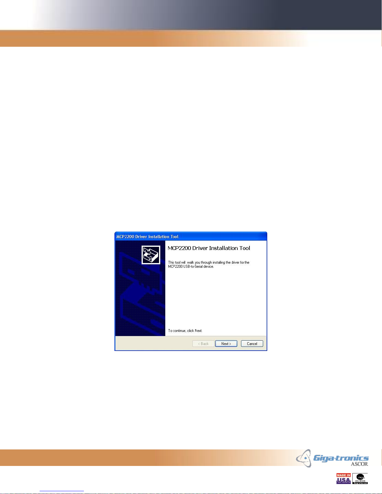
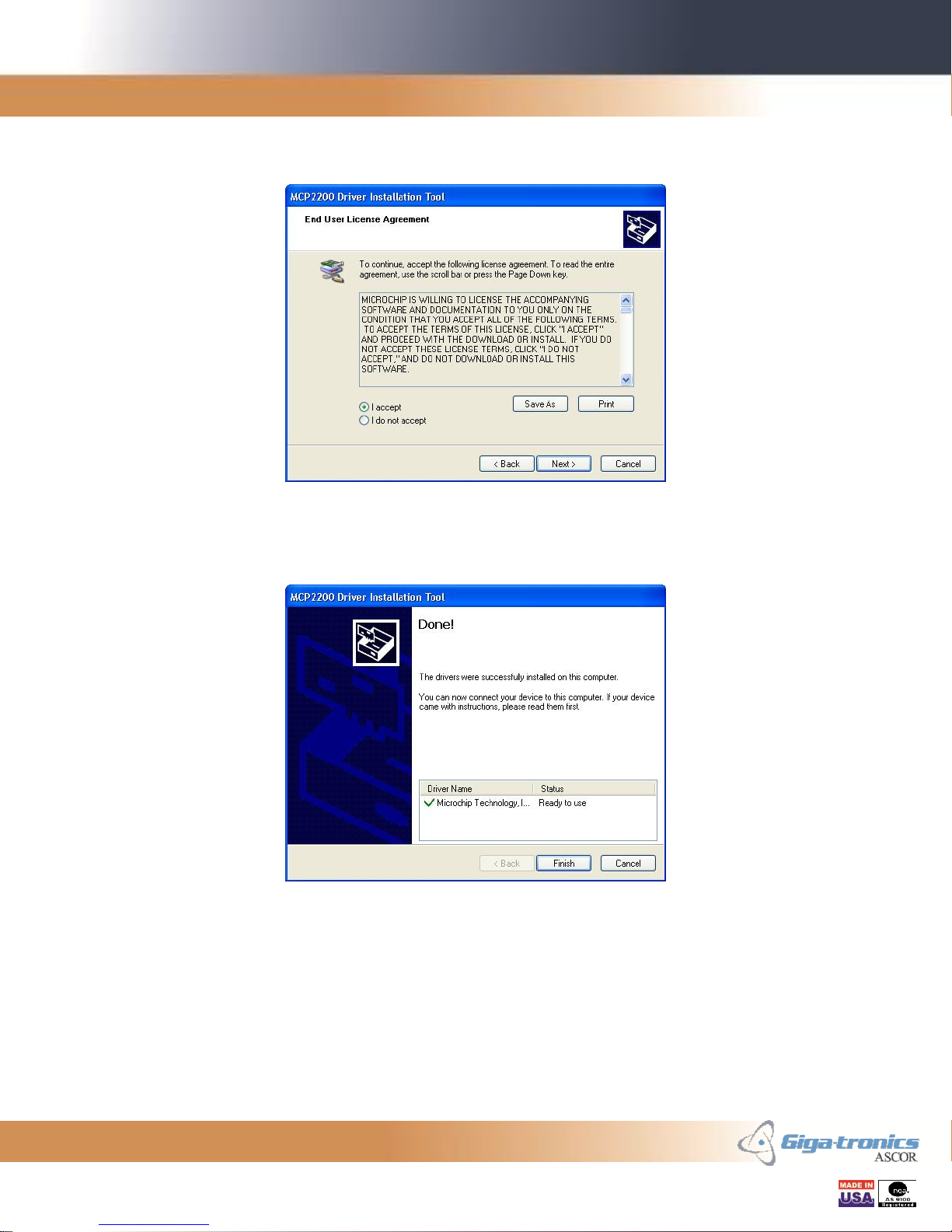
2.2 Installing the USB Device Driver...................................................................................................... 9
3. STARTING THE SERIES 8000 GUI PROGRAM....................................................... 11
3.1 Main Panel - Initialization Tab ...................................................................................................... 11
3.1.1 Live Mode .................................................................................................................................. 12
3.1.2 Simulation Mode ....................................................................................................................... 14
3.2 Main Panel - Switch Control Tab ................................................................................................... 15
3.2.1 Closing and Opening Switches using Virtual LEDs ..................................................................... 16
3.2.2 Closing and Opening Switches using Numerical Controls ......................................................... 16
3.2.3 Switch Access Count Indicators ................................................................................................. 16
3.3 Main Panel - Switch Table Tab ...................................................................................................... 17
3.4 Communication Panel................................................................................................................... 18
4. CONNECTING TO LAN-BASE SERIES 8000 SWITCH FOR THE FIRST TIME. 19
4.1 Equipment needed ....................................................................................................................... 19
4.2 Connecting to the Series 8000 Switch ........................................................................................... 19
4.3 Matching Your Computer’s IP Address to the Series 8000 Switch ................................................. 20
5. CHANGING THE IP ADDRESS OF THE SERIES 8000 SWITCH .......................... 21
5.1 Welcome Web Page...................................................................................................................... 21
5.2 Configuration Web Page ............................................................................................................... 22
5.3 Other Configuration Web Page Settings:....................................................................................... 22
5.4 Confirmation Web Page ................................................................................................................ 23
5.5 Rebooting Web Page .................................................................................................................... 24

Giga-tronics ASCOR SERIES 8000 Getting Started Guide Rev. C
Getting Started Guide, Part Number 07507593, Rev C, August 14, 2013
3 of 38
6. RESTORING FACTORY DEFAULT IP ADDRESS..................................................... 25
7. CONNECTING TO GPIB-BASE SERIES 8000 SWITCH FOR THE FIRST TIME26
7.1 Equipment needed ....................................................................................................................... 26
7.2 Connecting to the Series 8000 Switch ........................................................................................... 26
8. CHANGING THE GPIB ADDRESS OF THE SERIES 8000 SWITCH..................... 27
9. CONNECTING TO USB-BASE SERIES 8000 SWITCH FOR THE FIRST TIME. 28
9.1 Equipment needed ....................................................................................................................... 28
9.2 USB Device Driver Installation ...................................................................................................... 28
9.3 Identifying the COM Port .............................................................................................................. 28
9.4 Setting the COM Port parameters................................................................................................. 28
10. USB INTERFACE OPERATION .................................................................................... 29
10.1 Communication Settings .......................................................................................................... 29
10.2 Command Termination ............................................................................................................ 29
10.3 Communication Prompt ........................................................................................................... 29
11. COMMAND SET ............................................................................................................... 30
11.1 Switch Control Commands ....................................................................................................... 30
11.2 Switch Configure Commands.................................................................................................... 32
11.3 Switch Enabling Commands ..................................................................................................... 33
11.4 IEEE-488.2 Commands.............................................................................................................. 35
12. SAMPLE PROGRAM ....................................................................................................... 37

Giga-tronics ASCOR SERIES 8000 Getting Started Guide Rev. C
Getting Started Guide, Part Number 07507593, Rev C, August 14, 2013
4 of 38
Record of Changes
Revision
Description of Change
Chg Order #
Approved By
A
Initial Release
03579
TO
B
Added Installation Without IO Section
Added Commands Section
03587
TO
C
Fixed Sec. 3.2.2 SPDT/Transfer description
Fixed Typo “Ith” to”If”
Added Switch Configure Commands and
Switch Enabling Commands sections
Added sections for USB-based chassis
03593
TO

Giga-tronics ASCOR SERIES 8000 Getting Started Guide Rev. C
Getting Started Guide, Part Number 07507593, Rev C, August 14, 2013
5 of 38
1. Overview
This Getting Started Guide makes you familiarized with the controlling and programming
aspects of the Series 8000 Switch. It guides you through the GUI and I/O installation
process. Modification of the IP address for the LAN-based Series 8000 Switch and the
GPIB address for the GPIB-based Series 8000 Switch is described. A complete sample
program for Microsoft Visual C++ is provided at the end.
This guide can be used for different families of the Series 8000 Switch, such as Series
8000 Switch for LAN, GPIB, or USB, or 8901 and 8902 for LAN, GPIB, or USB.
The LAN-based Series 8000 Switch is a VXI-11.3 compliant instrument. VXI-11 is a
communication standard which utilizes RPC (Remote Procedure Call) and allows
communication between a controller and an instrument over LAN.
The GPIB-based Series 8000 Switch is an IEEE-488.2 compatible instrument.
The USB-based Series 8000 Switch is controlled via the USB bus using Microsoft’s
Virtual COM Port Driver.
All versions of the Series 8000 Switch are controlled with the VISA I/O. It is used for
making calls to communicate with the Series 8000 Switch. VISA I/O libraries are
available from National Instruments and Agilent Technologies.
Our installation program for the Series 8000 GUI program comes in two different
packages. The GUI program package installs the graphic runtime engine and the GUI
program. The GUI program plus I/O drivers package installs all the necessary I/O drivers
to gain access to the Series 8000 Switch. The latter package installs National Instruments
VISA Runtime Engine for the support of the LAN-based Series 8000 Switch, and
National Instruments IEEE-488.2 driver for the support of the GPIB-based Series 8000
Switch.

Giga-tronics ASCOR SERIES 8000 Getting Started Guide Rev. C
Getting Started Guide, Part Number 07507593, Rev C, August 14, 2013
6 of 38
2. Installing Series 8000 GUI Program, I/O and USB Driver
The following steps will guide you to install the GUI program for the Series 8000 Switch.
There are two different installation packages, one with only the GUI program and one
with the GUI program and the I/O driver. If you already have Agilent-VISA or NI-VISA
installed in your system you may choose the installation package with only the GUI
program. If you are installing on a fresh computer, choose the installation package with
the I/O driver.
Locate the appropriate Series 8000 SVP folder on the Installation CD or unzip the
appropriate Series 8000 SVP zip file to any temporary folder and run the setup.exe
program.
2.1 Installing Series 8000 GUI Program and I/O Driver
2.1.1 Setup Opening Panel
One of the two Opening Panels for the Installation program will appear. Click Next to
continue.
Figure 1 - Setup Opening Panel
Figure 2 –Setup with I/O Opening Panel

Giga-tronics ASCOR SERIES 8000 Getting Started Guide Rev. C
Getting Started Guide, Part Number 07507593, Rev C, August 14, 2013
7 of 38
2.1.2 Destination Directory Panel
Set the destination folder if you desire to install the Series8000 GUI or the I/O driver into
a different folder. In normal conditions, there is no need to change these folders. Click
Next to continue.
Figure 3 - Destination Directory Panel
2.1.3 License Agreement Panel
Please read the License Agreement and click on the “I accept the License Agreement”
radio button. Click Next to continue.
Figure 4 - License Agreement Panel

Giga-tronics ASCOR SERIES 8000 Getting Started Guide Rev. C
Getting Started Guide, Part Number 07507593, Rev C, August 14, 2013
8 of 38
2.1.4 Start Installation Panel
Verify the programs to be installed. Some sections may have already been installed in
prior installations. Click Next to continue.
Figure 5 - Start Installation Panel
2.1.5 Installation Complete Panel
Installation is completed. Click Finish to exit the installation program.
Figure 6 - Installation Complete Panel

Giga-tronics ASCOR SERIES 8000 Getting Started Guide Rev. C
Getting Started Guide, Part Number 07507593, Rev C, August 14, 2013
9 of 38
2.2 Installing the USB Device Driver
This section is for installing the USB Device Driver for Windows for USB-based Series
8000 Switch. If your Series 8000 Switch is not a USB-based version then you may skip
this section.
Before plugging in the USB-based Series 8000 Switch to your PC, a device driver for the
USB device must be installed for Windows to recognize the Switch chassis. The
following Windows versions are supported: Windows XP Service Pack 3 or later,
Windows 7 x86, and Windows 7 x64.
There are two versions of the installation program, one for the 32-bit Windows and the
other for the 64-bit Windows. x86 folder holds the installation program for the 32-bit
Windows and x64 folder holds the installation program for the 64-bit Windows. The two
folders are located under MCP2200 Driver Installation Tool folder in the installation
package.
Run the installation program MCP2200DriverInstallationTool.exe from the appropriate
folder and follow the instruction.
Figure 7 - USB Device Driver Initial Panel

Giga-tronics ASCOR SERIES 8000 Getting Started Guide Rev. C
Getting Started Guide, Part Number 07507593, Rev C, August 14, 2013
10 of 38
Please read the End User License Agreement and click on the “I accept” radio button.
Click Next to continue.
Figure 8 - USB Device Driver EULA Panel
Installation is completed. Click Finish to exit the installation program.
Figure 9 - USB Device Driver Done Panel
If the Series 8000 Switch was plugged in your PC before the driver was installed,
Windows may assign a wrong driver for the Series 8000 Switch. In such a case, unplug
the USB cable of Series 8000 Switch to the PC, uninstall the incorrect driver, restart
Windows, and install the USB Device Driver.

Giga-tronics ASCOR SERIES 8000 Getting Started Guide Rev. C
Getting Started Guide, Part Number 07507593, Rev C, August 14, 2013
11 of 38
3. Starting the Series 8000 GUI Program
After the successful installation of the Series 8000 GUI program, it can be started from
the Start Menu. Please follow one of the link below:
Start >> Series8000-SVP
Or
Start >> All Programs >> Giga-tronics >> ASCOR >> Series8000-SVP >> Series8000-SVP
3.1 Main Panel - Initialization Tab
The Series 8000 GUI program starts up in the Initialization Tab of the Main Panel. From
this tab you can connect to the Series 8000 Switch in live mode. Or you can run this
program in simulation mode.
Figure 10 - Series 8000 SVP Initialization Tab

Giga-tronics ASCOR SERIES 8000 Getting Started Guide Rev. C
Getting Started Guide, Part Number 07507593, Rev C, August 14, 2013
12 of 38
3.1.1 Live Mode
3.1.1.1 Connecting to the Series 8000 Switch
Series 8000 GUI supports LAN-based and GPIB-based Series 8000 Switch. Follow the
appropriate section below.
3.1.1.1.1 For LAN-based Series 8000 Switch
If this is the first time connecting to the LAN-based Series 8000 Switch, see Section 4
Connecting to LAN-based Series 8000 Switch for the First Time for more information.
Enter the IP Address of the Series 8000 Switch and click on Init button.
3.1.1.1.2 For GPIB-based Series 8000 Switch
If this is the first time connecting to the GPIB-based Series 8000 Switch, see Section 7
Connecting to GPIB-based Series 8000 Switch for the First Time for more information.
Select the GPIB address of the Series 8000 Switch and click on Init button.
3.1.1.1.3 For USB-based Series 8000 Switch
If this is the first time connecting to the USB-based Series 8000 Switch, see Section 9
Connecting to USB-based Series 8000 Switch for the First Time for more information.
Select the COM port of the PC that is used for the Series 8000 Switch and click on Init
button.

Giga-tronics ASCOR SERIES 8000 Getting Started Guide Rev. C
Getting Started Guide, Part Number 07507593, Rev C, August 14, 2013
13 of 38
3.1.1.2 Identification Information
After successful initialization, identification information is queried from the Series 8000
Switch and displayed on the display.
The format of the Identification Information is as follows:
<Manufacturer Name>, <Model>, <SN>, <Rev> <PartNumber>
Manufacturer Name is “ASCOR”.
Model is the model number and it is either “8000” for the unit that does not support
switch access counting capability. Or “8000-001” for the unit that supports switch access
counting capability. These two model numbers are used for all different variations of the
Series 8000 Switch including 8900 family.
SN is the serial number field of “S/N” header and a seven digit serial number of the unit
separated by a space.
Rev is the revision number field of “REV” header and a revision number of the chassis
assembly separated by a space.
PartNumber is the part number field of “P/N” header and a part number of the chassis
separated by a space.
The Identification Information can be queried again by simply clicking the Read IDN
button.
3.1.1.3 Manual Command Entry
Commands to the Series 8000 Switch can be manually from the Manual Command Entry
block.
Enter the command in the entry section on the right and click the Enter key of the
keyboard or click on the Write CMD button to send the command.

Giga-tronics ASCOR SERIES 8000 Getting Started Guide Rev. C
Getting Started Guide, Part Number 07507593, Rev C, August 14, 2013
14 of 38
3.1.1.4 Response Display
After a query command a response from the Series 8000 Switch is displayed in the
Response Display.
Enabling the Auto Query function will make the Series 8000 GUI program automatically
read the response after query command. If the Auto Query function is disabled, the
response to the query command can be read back by clicking on the Read button.
Clicking the Clear button clears the content of the Response Display.
3.1.2 Simulation Mode
If you do not have the Series 8000 Switch to connect or if you simply want to run the
Series 8000 GUI program in simulation mode, select the desired part number of the unit
to simulate from the Part Number pull down menu and click the Simulate button.
The controls and displays for the functionalities that are not supported in simulation
mode are dimmed out and cannot be used. Any responses to the query commands are not
simulated and default values are used instead.

Giga-tronics ASCOR SERIES 8000 Getting Started Guide Rev. C
Getting Started Guide, Part Number 07507593, Rev C, August 14, 2013
15 of 38
3.2 Main Panel - Switch Control Tab
The Switch Control Tab gives the capability to toggle the switch by simply clicking on
the desired pin. This tab represents the front panel of the connected Series 8000 Switch
that was automatically identified by the GUI program. In simulation mode this tab
represents the front panel of the Series 8000 Switch selected by Part Number pull down
menu in the Initialization tab.
The Series 8000 GUI supports various types of Series 8000 Switch. The panel below
shows the virtual panel for the Model 8902 which can be identified by the part number
90570310 displayed on the sub tab.
Figure 11 - Series 8000 SVP Switch Control Tab
The green or yellow color on the virtual LED signifies the associated pins are connected
together. The black pins signify that there are no connections between the pins.
Figure 12 - SP6T Switch Block
Figure 13 - SPDT Switch Block
Figure 14 - Transfer Switch
Block

Giga-tronics ASCOR SERIES 8000 Getting Started Guide Rev. C
Getting Started Guide, Part Number 07507593, Rev C, August 14, 2013
16 of 38
3.2.1 Closing and Opening Switches using Virtual LEDs
The switch can be controlled by clicking on the virtual LEDs.
For SP3T, SP4T, SP5T, SP6T, and SP8T switches, click on the unlit (black) virtual LED
corresponding to the physical switch pin to connect a path from the corresponding pin to
the common pin. Two virtual LEDs will light up indicating the corresponding path is
closed. Click on either of the lit (green) virtual LEDs to open the connected path.
For SPDT switches, click on the virtual LED for the Normally Open (NO) to connect the
path from Common to Normally Open. This is an energized or on state. Click on the
virtual LED for the Normally Closed (NC) to connect from Common to Normally
Closed. This is a de-energized or off state. Alternatively, click on the virtual LED for
Common (C) to toggle between Normally Open and Normally Closed states.
For Transfer switches, click on the top right virtual LED to connect the path from
Common to Normally Open. This is an energized or on state. In this state the paths
along the horizontal pins are connected. Click on the bottom left virtual LED to connect
the path from Common to Normally Closed. This is a de-energized or off state. In this
state the paths along the vertical pins are connected. Alternatively, click on the top left or
bottom right virtual LEDs to toggle between Normally Open and Normally Closed states.
3.2.2 Closing and Opening Switches using Numerical Controls
The switch can be controlled by selecting the desired position using the numerical control
associated to the switch.
For SP3T, SP4T, SP5T, SP6T, and SP8T switches, the numerical control can be used for
setting the switch to the desired position. Set to 0 to open the switch. Set to non-zero to
close the switch to the desired position. The maximum position varies depending on the
available poles of the switch.
For SPDT and Transfer switches, the numerical control can be used for selecting on and
off states. Set to 0 for the off state. In this state the Common pin will connect to the
Normally Closed pin. Set to 1 for the on state. In this state the Common pin will connect
to the Normally Open pin.
3.2.3 Switch Access Count Indicators
For the Series 8000 Switch where counting capability is available, the counting indicator
displays the running access count of the associated switch.

Giga-tronics ASCOR SERIES 8000 Getting Started Guide Rev. C
Getting Started Guide, Part Number 07507593, Rev C, August 14, 2013
17 of 38
3.3 Main Panel - Switch Table Tab
The Switch Table Tab lists all the possible switches for the selected chassis. The table
has six columns –Label, Conn, Available, SW, Count, and Serial Number. The “Label”
column shows the label of the switches on the Series 8000 Switch front panel. The
“Conn”column shows the J-numbers of the socket on the driver board where the plugs of
the switch cables connect. The “Available”column shows the availability of the switch.
The “SW”column shows the switch number used in switch commands. The “Count”
column shows the running access count of the switch. This count can be modified to any
desired value. The “Serial Number”column shows the serial number of the switch.
In simulation mode, Counts and Serial Numbers can be changed in the Switch Table but
cannot be saved and gets reverted to their respective default values.
Figure 15 - Series 8000 SVP Switch Table Tab
Click on the Read Table button to restore the Switch Table with
the information stored in the Series 8000 Switch flash memory.
Click on the Save Table button to update the Series 8000 Switch
flash memory with the information in the Switch Table.

Giga-tronics ASCOR SERIES 8000 Getting Started Guide Rev. C
Getting Started Guide, Part Number 07507593, Rev C, August 14, 2013
18 of 38
3.4 Communication Panel
The Communication Panel displays the commands sent from the Series 8000 GUI and
responses returned from the Series 8000 Switch.
Figure 16 - Communication Panel
You can select what gets displayed by toggling the radio button corresponding to the type
of communication. Select the Commands radio button to
display the commands sent to the Series 8000 Switch. Select the
Responses radio button to display the responses returned from the Series
8000 Switch.
Click the Clear Log button to clear the items displayed in the Communication Log
display.
In simulation mode, only the outgoing commands are displayed. Not responses are
simulated.

Giga-tronics ASCOR SERIES 8000 Getting Started Guide Rev. C
Getting Started Guide, Part Number 07507593, Rev C, August 14, 2013
19 of 38
4. Connecting to LAN-base Series 8000 Switch for the First
Time
4.1 Equipment needed
First your computer must be equipped with the network capability. Second you will need
an RJ-45 network cable. If you are connecting the Series 8000 Switch directly to the
computer, you may need to use a special crossover cable, especially if your computer
does not have an auto-sensing functionality.
4.2 Connecting to the Series 8000 Switch
When you are connecting to the Series 8000 Switch for the first time, care has to be taken
to have the IP address of the computer and the Series 8000 Switch in the same subnet.
The Series 8000 Switch comes with a factory default IP address of 192.168.0.254. Verify
this address with the IP address labeled next the LAN cable plug on the back of the Series
8000 Switch.
Make sure your computer’s IP address belongs to the same subnet and do not have any IP
address conflict with the Series 8000 Switch or any other devices that are connected in
the network. If you need to change the computer’s IP address go to the Section 4.3
Matching Your Computer’s IP Address to the Series 8000 Switch.

Giga-tronics ASCOR SERIES 8000 Getting Started Guide Rev. C
Getting Started Guide, Part Number 07507593, Rev C, August 14, 2013
20 of 38
4.3 Matching Your Computer’s IP Address to the Series 8000 Switch
In order to communicate to the Series 8000 Switch via LAN or to change the IP address
of the Series 8000 Switch, your computer’s IP address must be in the same subnet with
the Series 8000 Switch. You can modify your computer’s IP address from the Internet
Protocol Version Properties dialog box in Windows.
Figure 17 - Internet Protocol Version Properties
Click on the “Use the following IP address” radio button and enter the new IP address of
the computer. Your new IP address should match the first three octets of the IP address
Series 8000 Switch, 192.168.0 in this case. The last octet should be something unique,
100, in this case. Enter “255.255.255.0” for the Subnet mask. Click OK until you exit all
the dialog boxes.
Table of contents
Other Giga-tronics Switch manuals
Popular Switch manuals by other brands

Avaya
Avaya M770 user guide

TP-Link
TP-Link JetStream TL-SG3210XHP-M2 installation guide

Cisco
Cisco Catalyst 4500 E Series Supervisor Engine 9-E Installation and configuration note

steute
steute Ex ZS 80-3G Mounting and wiring instructions

Sony
Sony BKDS-7017 installation manual

Arista
Arista DCS-7010T-48 quick start guide

Luxlink
Luxlink OSM-5222-84 operating instructions

NETGEAR
NETGEAR GS716T - ProSafe Switch Specifications

Hyundai Electric
Hyundai Electric U Series instruction manual

Black Box
Black Box SWI080A-R3 Specifications

Magicfx
Magicfx FX-SWITCHPACK User and installation manual

Allied Telesis
Allied Telesis AT-PC232/POE datasheet