GILANI ENGINEERING MT02 User manual

USER MANUAL
Handbike For Manual Wheelchair
Before using the handbike, please read this user
manual carefully and save it for reference.
MODEL:MT01/MT02/MT03/MT04
MT02

Contents
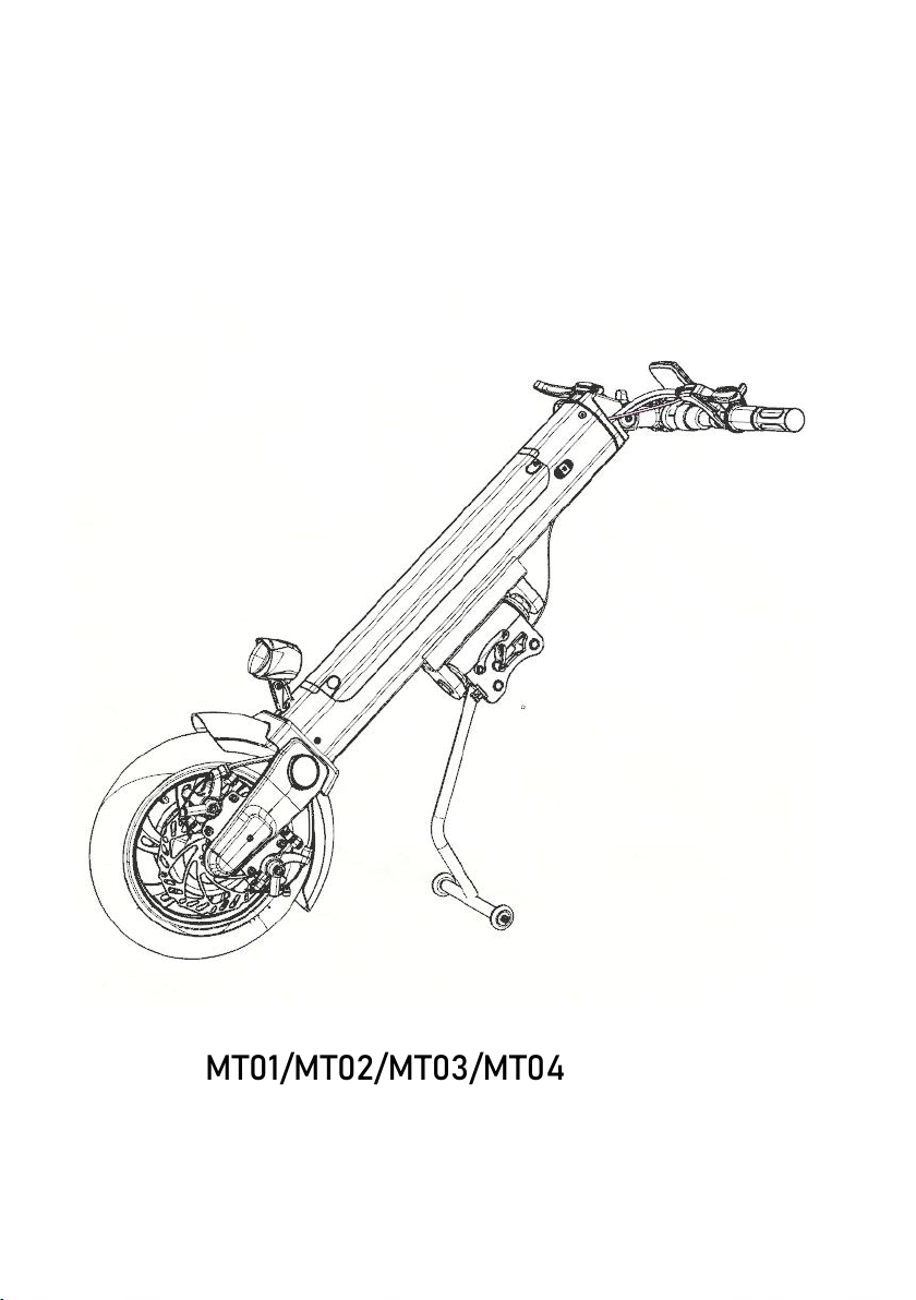
Product description .....................................................................................- 2 -
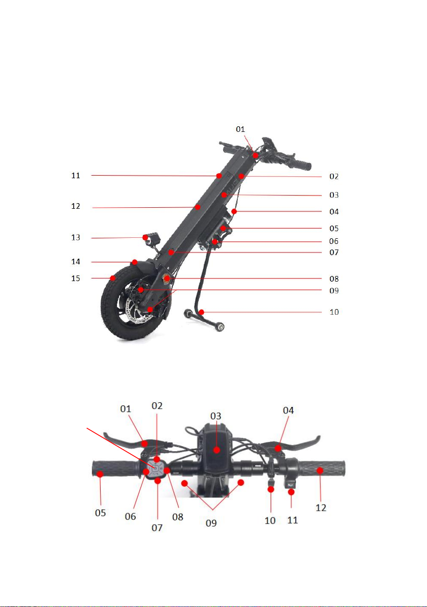
MT01&MT02 Structure ...........................................................................- 2 -
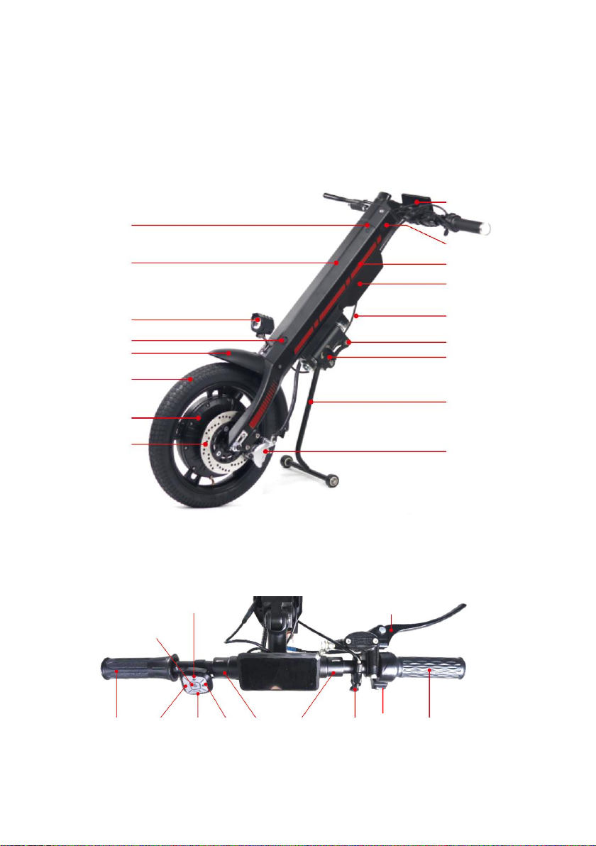
MT03&MT04 Structure ...........................................................................- 3 -
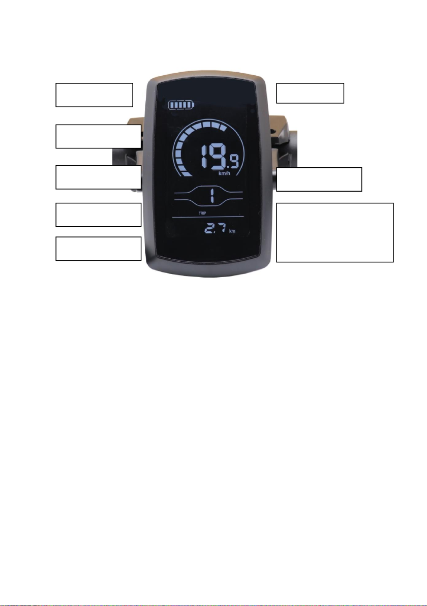
Technical Parameters and Indicators ....................................................... - 6 -
Product main parameters .......................................................................- 6 -
First time connecting with wheelchair instruction .................................. - 8 -
Wheelchair installation location ............................................................- 10 -
Handbike body Installing ..........................................................................- 11 -
Foot support ......................................................................................... - 11 -
Handlebar assembly ............................................................................ - 11 -
Brake lines assembly ........................................................................... - 12 -
Electric control wiring ........................................................................... - 12 -
Hook remote control .............................................................................- 12 -
Structure on both sides instruction .......................................................- 12 -
Intermediate structure description ........................................................- 14 -
Assembly of structures on both sides ....................................................- 15 -
Intermediate structure description ..........................................................- 18 -
Ground clearance adjustment ..................................................................- 20 -
Bilateral structure adjustment method ................................................... - 20 -
Intermediate structure adjustment method ............................................ - 20 -
Disconnecting with wheelchair ................................................................- 21 -
Battery Instructions ...................................................................................- 22 -
Related battery instructions ..................................................................- 22 -
Battery Usage .......................................................................................- 22 -
Notes for charging .....................................................................................- 23 -
Battery Installation and removal ..............................................................- 24 -
Battery Charging ....................................................................................... - 25 -
Warranty Coverage ....................................................................................- 26 -
Warranty Card ............................................................................................- 26 -
Not covered by warranty .......................................................................... - 29 -

-2-
Product description
MT01&MT02 Structure
1. Handlebar 2. Battery lock button 3. Battery indicator 4. Hook control line 5. Rotating shaft sleeve
6. Lock button for rotating shaft sleeve 7. Charging port 8. Reflector 9. Disc plate 10. Foot support
11. Battery indicator light 12. Battery 13. Front light 14. Fender 15. Tyre
1.Left brake bar 2.Speed+ 3.Display 4.Right brake bar 5.Left handlebar 6.Switch over
7.Speed-/Back up 8.Headlight 9.Folding handlebar switch 10.Wire switch of connector 11.Horn
12.Right handlebar 13.Power
13

-3-
Battery display
Fault indication
Speed display
Gear indication
Numerical value
Headlights
Unit of velocity
Single mileage display
Total mileage display
Maximum speed display
Average speed display

-4-
MT03&MT04 Structure
1. Handlebar 2. Battery lock button 3. Decoration 4. Controller shell 5. Hook control line 6.Rotating shaft
sleeve 7.Lock button for rotating shaft sleeve 8. Reflector 9. Hydraulic brake system 10. Battery indicator
11. Battery 12. Headlights and horns 13. Charging port 14. Fender 15. Tyre 16.Electric machine 17.Brake
disc
1.Left brake bar 2.Power 3.Display 4.Speed+ 5.Speed-/Back up 6.Switch over 7.Folding handlebar switch
8.Wire switch of connector 9.Horn 10.Right brake bar 11.Right handlebar /Accelerator
02
01
04
05
06
07
08
09
03
10
11
12
13
15
16
14
17
01
02
03
04
05
06
07
08
10
11
09

-5-
Battery display
Speed display
Gear indication
Headlights
Single mileage display
Total mileage display
Maximum speed display
Average speed display

-6-
Technical Parameters and Indicators
Product main parameters
MT01&MT02
Size and weight
Expanded size (length x width x height)
1100*570*800mm
Folded size (length x width x height)
1120*460*410mm
Weight capacity
120kg
Self-weight
14.1kg (Without battery)
Motor
Type
Brushless DC motor
Rated power
350W
Input voltage
DC 36V
Number
1 PC
Brake system
Disc brake
Battery
Type
Lithium-ion Battery
Nominal capacity
13 Ah/20 Ah
The output voltage
DC 36V
Number
1(If not used for 2 weeks, charge once)
Controller

-7-
Type/plug type
Brushless DC sine wave controller
Output voltage/current
DC 36V
Charger
Type
Take away portable
Input voltage
AC: 100~240V,50Hz
The output voltage
36V
Tires
Outer diameter x tire width
12.5 Inch *2.125 Inch
Type
Pneumatic tire
Material
Rubber
Number
1 PC
Performance
Horizontal road braking performance
≤3m
Maximum safe slope performance
≤3m (8°)
Climbing ability
≤8°
Theoretical driving distance
30-40km
Maximum Speed
25km/h

-8-
MT03&MT04
Size and weight
Expanded size (length x width x height)
1050*650*860mm(Stance)
Packing size (length x width x height)
1170*520*310mm
Weight capacity
120kg
Self-weight
21kg(17kg Without battery)
Motor
Type
Brushless DC motor
Rated power
≥800 W
Input voltage
DC ≥48V
Number
1 PC
Brake system
Hydraulic brake
Battery
Type
Lithium-ion Battery
Nominal capacity
12Ah
The output voltage
DC ≥48V
Number
1
Controller
Type/plug type
Brushless DC sine wave controller
Output voltage/current
DC ≥48V

-9-
Charger
Type
Take away portable
Input voltage
AC: 100V~240V(±2%V),50Hz(±1%Hz)
The output voltage
≥48V
Tires
Outer diameter x tire width
16 Inch *2.125 Inch
Type
Pneumatic tire
Material
Rubber
Number
1 PC
Performance
Maximum speed
≤30km/h
Horizontal road braking performance
≤3m
Maximum safe slope performance
≤3m (10°)
Climbing ability
≤12°
Theoretical driving distance
40-50km

- 10 -
First time connecting with wheelchair instruction
Wheelchair installation location
01
02
03
04

- 11 -
Handbike body Installing
Foot support
As shown in the picture, use a wrench to loosen the pre-installed screws, then align
the holes of the feet and tighten the screws.
Handlebar assembly
As shown in the picture, remove the pre-installation screws of the handbike, align the
handlebar assembly with the hole, insert the rotating shaft, adjust the handlebar to a
suitable angle, and then tighten the screws on both sides.

- 12 -
Brake lines assembly
1) As shown in the picture, unscrew the screw
at the end of the brake lever counterclockwise and
put the brake cable head into the prefabricated
buckle and then tighten the screw.(Note: This step
is not required for MT03&04)
2) Grasp the brake cable at the tail end, as
shown in the picture, then connect the brake cable
and tighten the screws to check whether the brake
force is appropriate. If it is too loose, it is
recommended to continue to adjust.(Note: This
step is not required for MT03&04)
Electric control wiring
Find the thread with the same color, and make
sure to insert it tightly as indicated by the arrow.
(Note: Do not drag the wire group forcefully,
otherwise it will damage the circuit and cause
unpredictable consequences.)
Hook remote control
As shown in the picture, loosen the pre-installed
screws, install the wire control on the right
handlebar and tighten the screws.

- 13 -
Structure on both sides instruction
1) Open the package to find the spacer and
knob, insert the spacer first and screw the knob
on.
2) Loosen the nut, you can slide the clamp left
and right to adjust the spacing.
3) Eight nuts adjust the hook angle, with the
middle four nuts adjusting the hook height.

- 14 -
Intermediate structure description
1) Open the package to find the spacer and
knob, insert the spacer first and screw the knob
on.
2) Loosen the nut, insert the fixing ring and
clip.
3) Insert the intermediate connecting rod until
a click is heard indicating it has been locked;
Pushing up the bottom switch can unlock and
pull out the connecting rod.(Be sure to insert the
intermediate connecting rod in place, otherwise
there is a risk of detachment)

- 15 -
Assembly of structures on both sides
1) Lift up the handbike body, lift the head of the handbike and keep the body and
the rotating shaft sleeve on the same line, then turn the knob to the "P" position, and
the head of the handbike can stand stably at this time. (Note: If the knob is not
screwed in place or the rotation encounters resistance, please rotate the head of the
handbike left and right at a small angle and try to screw the knob in place again)
2) As shown in the picture, loosen the fixing screws on both sides of the pipe clip
and adjust the distance between the two clips to make it consistent with the front
pipe of the wheelchair.

- 16 -
3) As shown in the figure, loosen the
pipe clamp screws on both sides so that
the clamp can be rotated to the
matching angle of the front tube of the
wheelchair. (Note: Take the 03
wheelchair as an example this time,
different wheelchairs are clamped in
different positions, please refer to the
previous chapter for wheelchair
installation and adaptation for details)
4) As shown in the picture, clamp the pipe clamp to the front tube of the
wheelchair so that the upper end of the hook is on the same level as the handbike
bushing. At this time, measure the
distance between the upper hook and
the ground at about 40cm, indicating
that the height of the hook is
appropriate, and then tighten the screws
so that the entire connecting piece can
be firmly clamped in the front tube of
the wheelchair.

- 17 -
5) As shown in the figure, drag the front of the handbike back until the upper hook
is hooked in, hold the handlebar and push the handlebar forward and upward (70-80°
relative to the ground) until a click sound is heard, indicating that the hook has been
connected in place, and then Turn the knob to the "D" position, and the lower hook is
locked at this time. (Note: Be sure to rotate in place, otherwise there may be
decoupling or steering stuck, etc.)
6) Insert the battery into the front of the handbike, press the top of the battery
until you hear a click sound, indicating that the battery has been installed in place,
test whether the gear position, horn, light and hook wire control are normal, the
above is completed, then congratulations, you can ride the handbike as much as you
want.

- 18 -
Intermediate structure description
1) Lift up the handbike body, lift the head of the handbike and keep the body and
the rotating shaft sleeve on the same line, then turn the knob to the "P" position, and
the head of the handbike can stand stably at this time. (Note: If the knob is not
screwed in place or the rotation encounters resistance, please rotate the head of the
handbike left and right at a small angle and try to screw the knob in place again)
2) Adjust the distance between the two clamps so that they hold the wheelchair,At
this time measure the distance between the upper hook and the ground at about
40cm.
40cm

- 19 -
3) As shown in the figure, drag the front of the handbike back until the upper hook
is hooked in, hold the handlebar and push the handlebar forward and upward (70-80°
relative to the ground) until a click sound is heard, indicating that the hook has been
connected in place, and then Turn the knob to the "D" position, and the lower hook is
locked at this time. (Note: Be sure to rotate in place, otherwise there may be
decoupling or steering stuck, etc.)
4) Insert the battery into the front of the handbike, press the top of the battery
until you hear a click sound, indicating that the battery has been installed in place,
test whether the gear position, horn, light and hook wire control are normal, the
above is completed, then congratulations, you can ride the handbike as much as you
want.
Table of contents
Other GILANI ENGINEERING Mobility Aid manuals