GILANI ENGINEERING Accessiblehoist User manual

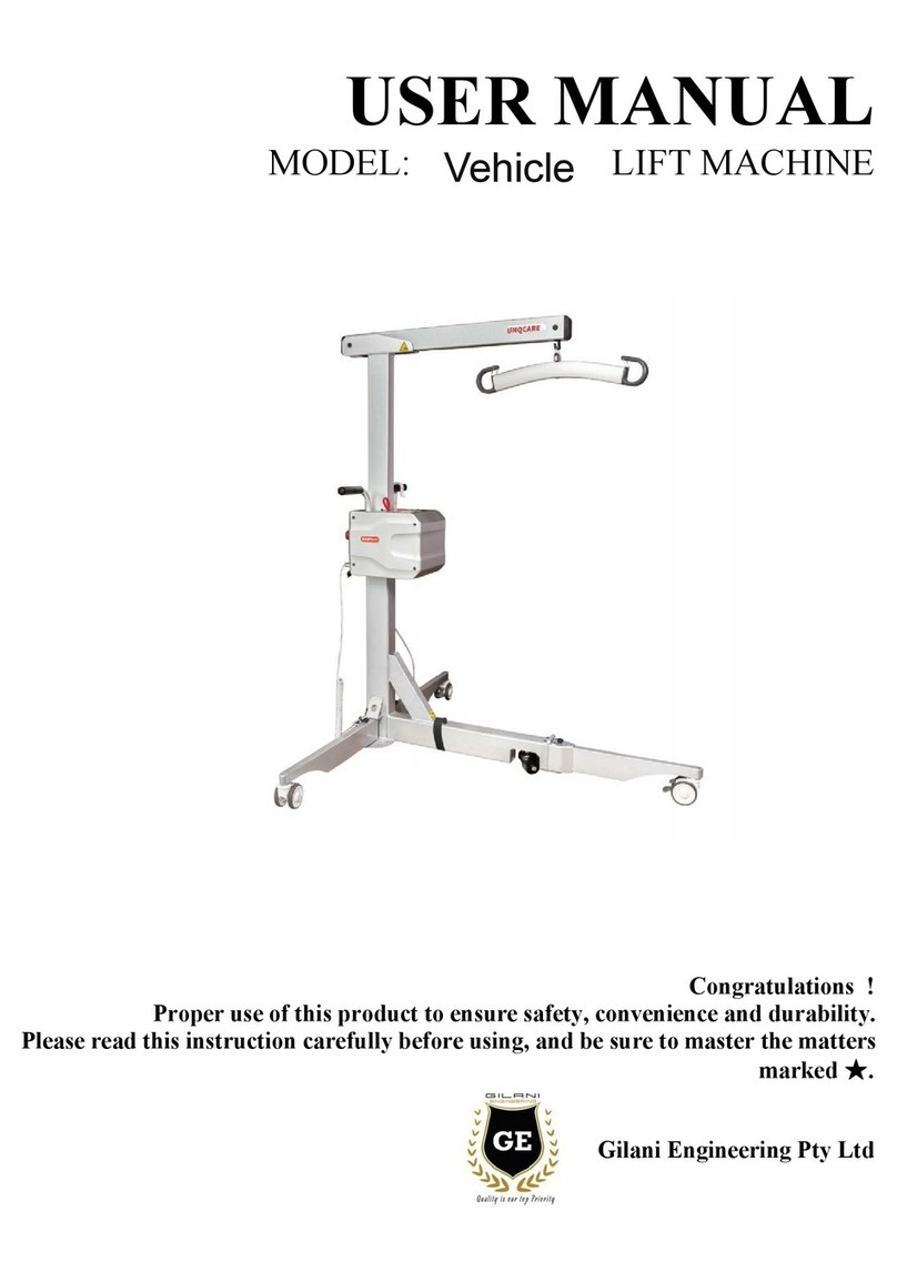
USER MANUAL
MODLE: GE-HY202 LIFT MACHINE
Proper use of this product is the prerequisite to ensure safety, convenience and
durability
Please read this instruction carefully before using, and be sure to master the matters
marked with the mark ★
Gilani Engineering Pty Ltd
Accessiblehoist

Catalogue
Ⅰ. Safety Instruction........................................................................................................................... 1
Ⅱ. Product Drawing...........................................................................................................................1
Ⅲ. Specification................................................................................................................................2
Ⅳ. Installation...................................................................................................................................2
Ⅴ. User Guide....................................................................................................................................5
Ⅵ. Battery Charging......................................................................................................................... 7
Ⅶ. Maintenance...............................................................................................................................8
Ⅷ. Trouble Shooting...................................................................................................................... 8
Ⅸ. Warranty......................................................................................................................................9
X. Maintenance Record...................................................................................................................10
△
NOTES:
This manual contains important information about the product. Please read
carefully and fully understand it before using. Remember to keep this manual
somewhere you can always find it.

1
Ⅰ. Safety Instruction
1.
Please ensure the following items before the first using:
●
The shifter is installed according to the instruction;
●
Make sure the battery is fully charged or charged for at least 6 hours;
2.
Need to check the items before using:
●
All accessories are not damaged;
●
Choose the right accessories according to the patient’s condition;
●
Under no circumstances shall the shifting machine be modified.
●
Pay attention to avoid local high frequency equipment, transmitters and receiver when using.
Ⅱ. Product Drawing
1. Waist brace tube
2. Front lift tube
3. Hanging head
assembly
4. Knee pad
5. Foot base
6. Right foot tube
7. Rear lift tube
8. Main frame tube
9. Connecting tube
10. Foot pedal
11. Left foot tube

2
Ⅲ. Specification
Ⅳ. Installation
1、Open-box inspect
Please check if accessories are lost(Please refer to the following list),if any
damage or lost, please contact the distributor in time.
Overall size
1200x1320x665
Button unfold size
885mm
Motor
24V/8000N
Lifting speed
8.3mm/s
Protection class
IP54
Net weight
57kg
Max load
200kg
Lifting times per charge
60-80times
Cross height
10mm
Lifting range of boom
870-1750mm
Lifting range of waist brace
1020-1650mm
Knee pad adjustment range
555-680mm

3
1.
Installation steps
Step 1: Raise the body frame,Screw the M10x75
outer hexagon bolt as drawings.
①Bolt M10x75 ②Gasket
③Nylon lock nut M10 ④Nut
Step 2: Connect the rear lift tube with the
body frame shown in the drawing, tighten by
M10x50 Hexagon bolt and nuts .
①Hexagon socket shoulder screw M10X50
②Gasket ③Nylon lock nut M8 ④Nut
Step 3: Install the motor, tighten by
M10x40 Hexagon bolt and nuts
①Hexagon socket shoulder screw M10x40
②Gasket ③Nylon lock nut M8 ④Nut
Step 4: Install waist brace tube, Align the two pins
on the waist brace tube to the two holes on the rear
lifting tube
press down, hear a “click”

4
Step 5: Insert the front lift head into
the rear lift tube ,pull the bigger index
plunger, the front/rear lift tube ends
coincide, loosen to reset the indexing
pin.
Step 6: Pedal knee pad installation ,using a 2.5mm
hexagon wrench, unscrew the M3 screw and hand
twist plum screw, then install the kneecap pad into the
square pipe on the pedal, and then unscrew the M3
screw and hand twist plum screw. Knee pad
adjustable, hand twist plum screw fixed. Install the
installed pedal knee pad to the shift machine.
Step 7:Control box installation
1、Lock the two mounting screws(M5x10)
2、Turn the lock to the opening direction, install the control box on the screws of the
main frame and tighten the upper screws
3
、Lock the control box by turning the lock 90° clockwise

5
Ⅴ. User Guide
1. Control handle operation
Up/down key to control the boom up and down, release to stop motion
2.Base width adjustment
Adjustment by foot pedal. Step on the left to widen,
step on the right to narrow
3.Emergency stop button to cut the power supply, stop the lifting machine immediately in case of sudden
danger.
Off:press red button, control the device to be closed
On:Rotate red button clockwise,showing as B,Control machine can work normally.
Strong Suggestion: Press this button when the device has not been used for more than 3 days.In this way,
the batteries can be maintained for a long time.
4.Electric emergency up and down key
If the control handle breaks down or there is no
control handle, use the up or down keys to return
the motor to position.
5.Control Device connection
This device has four sockets, one for the control handle, two for motors, and another for the power
supply.
Control handle sockets
Motor sockets1
Electrical sockets
Motor sockets
Up Key
Down
Key

6
Release
Brake
6.Manual emergency low down
For emergency manual low down, turn the red sleeve
in the direction of the arrow shown.
7.Rear wheel release and brake
The rear wheel can be locked to prevent
rotation and
lateral movement. Brake
Warning: Locking the wheel during lifting movement
increases the risk of tipping over the lifting equipment.
Note: We recommend locking the wheel only when
there is a risk of personal injury from sliding, for
example, by lowering the patient from a horizontal
position to the ground.Release the wheel brake and lift .
8.Operation of shift machine
1) keep safe operation
Always keep the arm perpendicular to the client’s
center of gravity.Ensure proper operation of the
shift machine before each use.
Warning: Unbalanced rise creates the danger of
toppling
2、The position of the shift machine

7
When in use, the waist tube, pedal knee pad assembly with standing shift function and the front
lifting pipe hanger assembly with conventional shift function cannot be installed on the shift
machine simultaneously.
When using the standing shift function, remove the front lifter hanger assembly from the shift
machine.
(The sling should choose the right gear according to the user’s figure)
Ⅵ. Battery Charging
1. When the battery power is only 1 bar left, the control box will alarm 4 continuous beeps,
prompting to charge immediately. If not charged, the motor will not work .
2. Battery charging
When the battery beeps, turn off the emergency stop button, plug in the power supply and
charge.Full charge is the display of four grids of power, the control box on the LED light no
longer flashing.
NOTES:
1) When charging, please turn off the emergency stop button to recharge
2) When the shift machine is not in use for a long time, remove the control box and place it in a
cool and dry place. Charge it once every month;
3) Do not charge in a humid environment;
4) If the shift machine is not used every day, it is strongly recommended to turn off the emergency
stop button, which can disconnect the current and save the battery power.

8
Ⅶ. Maintenance
For safe operation, please check and test before use.
1. Check that the screws and fixing nuts on the boom are tight;
2. Check control handle, lift and width adjustment movement;
3. Check the emergency drop function(electric and manual);
4. Check that the safety hook on the boom is normal.
Attention! Chemical substances containing phenol and chlorine should not be used to wipe the shift
machine, which will damage the plastic powder and plastic materials.
Transportation and Storage
When the device is not used for a long time, press the stop button. Storage ambient
temperature above 0℃, normal relative humidity (≤60 )
Inspect
Have a complete checkup at least once a year. Pay special attention to areas where wear occurs,
such as joints, bolts, etc.
Ⅷ. Trouble Shooting
Couldn’t lift or land
1. Check whether the emergency stop button is pressed
2. Check whether the wire of is connected correctly
3. Check battery power
4. Check whether the battery contact panel has problems or damages
5. If the electric shift machine is not working, please contact the
after-sales service
Charging failure
1. Check whether the charger is plugged into the socket
2. Check the battery contact panel for problems or damage
3. If the charger still does not charge, please contact after-sales
service
It stops while lifting
1. Check whether the emergency stop button is pressed
2. Use an emergency descent device
3. If the electric shift machine is not working, please contact the
after-sales service.

9
Ⅸ. Warranty
Date from you get the lifting machine
1. The control box shall be replaced within six months and guaranteed within one year.
2. The battery shall be replaced if its capacity is less than 60% of the rated capacity within half a
year.
3. The rest parts are provided for free maintenance.
4. Wheels, foot MATS and plastic parts (wearing parts) are not within the warranty period. If they are
damaged during use, please contact the dealer.
5. If there are batch quality problems, the company is responsible for sending someone to repair or
recall them.
6. Paid service will be available after one year
The warranty not cover :
1. Not properly used in accordance with the instructions
2. Not using parts manufactured by the Company
3. Parts are damaged due to accidents.
4. Consumable goods are not included in the warranty scope, refer to wheels, sling, etc.
5. Unauthorized modification of device Settings is not allowed.
6. Typhoons, floods, earthquakes and other natural disasters
User's Name:
Address:
Contact number:
Product Name:
Bar code:
Date of purchase:
Contact of dealer
Note: the buyer is requested to register the warranty with the dealer within one month.
This card is sealed by the dealer or manufacturer.

10
Maintenance record
Date
Problems
Causes
Note
X. Maintenance Record
Table of contents
Other GILANI ENGINEERING Mobility Aid manuals
Popular Mobility Aid manuals by other brands

Gemino
Gemino 30 Walker user manual

Invacare
Invacare RBL250 Assembly, installation and operating instructions

Enabling Devices
Enabling Devices Ultimate Switch user guide

Unitron
Unitron Element Programming guide

NRS Healthcare
NRS Healthcare M29495 User instructions

Direct Healthcare Group
Direct Healthcare Group Bure Rise & Go user manual