GILANI ENGINEERING Vehicle User manual

USER MANUAL
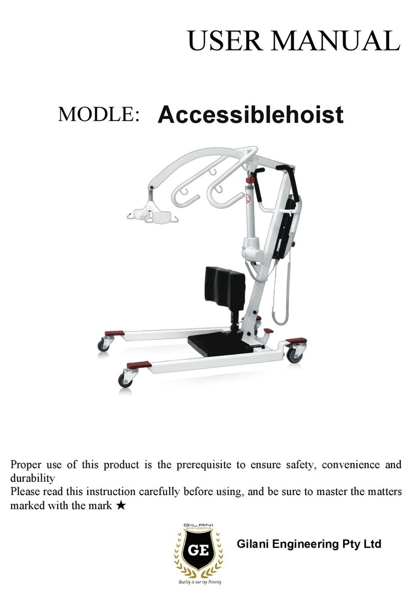
MODEL: GE-HY302 LIFT MACHINE
Congratulations !
Proper use of this product to ensure safety, convenience and durability.
Please read this instruction carefully before using, and be sure to master the matters
marked ★.
Gilani Engineering Pty Ltd
Vehicle

Catalogue
1. Product Drawing....................................................................................... 1
2.Specification...............................................................................................1
3.Installation.................................................................................................. 2
4.Operation.................................................................................................... 5
5.Battery Charging........................................................................................ 7
6.Maintenance............................................................................................... 7
7.Trouble shooting........................................................................................ 8
8.Warranty.....................................................................................................8

1
1
8
3
2
9
4
10
5
6
7
1. Product Drawing
1. Lift arm
2. Internal tube
3. Handle
4. Motor box
5. External tube
6. Front support tube
7.Side support tube
8. Suspender
9. Controller
10.Scram stop button
2.Specification
Overall size :1235 mm×1180 mm×1450 mm( length × width × height)
Fold size :850 mm×252 mm×940 mm( length × width × height)
Motor :200 VA
Lifting speed :12 mm/s
Battery :24 V 5Ah lithium battery
Maximum load :120 kg
Net weight :19 kg
One charge can be lift 80-100 times
Minimum distance from the ground :26 mm
Lift range: mm 845-1367
Noise :≤65 dB (A)

2
3.Installation
3.1 Open-box inspect
Please check if accessories are lost (Please refer to the following list), if any damage or
lost, please contact the distributor in time.
Item
Quantity
Description
Frame+ controller
1 set
Suspender assembly
1 pc
Suspension
1 pc
Charger
1 set
Manual book
1 set
Tools
1 set
3 mm Hexagon wrench 1pc
22 mm wrench 1pc
3.2 Unfold steps
Step 1: Pull the pin, expand the two side legs, then expand the front leg, and finally expand the suspender;
Step 2:Pull the handle up first, then flip 90 degrees outward, then press down to a fixed position.
★Note: when expanding the side leg, lift the pin ①up and rotate the side leg outward. When you hear a
"Click ", the side leg was fixed.
3.3 Install castor (Accessories)
Use the 22mm wrench to install the castor .
4
3
1
2
1
1

3
3.4 Controller and Operation Panel
You can use the cable controller or control panel on motor box to control the machine.
①Lighting : Power On.
②Battery light:
Orange lighting : Battery needs to be charged .
③④ up / down button:
Push to rise or fall, release to stop moving.
⑤Emergency down button: In case of emergency, long press ⑤
button and lift down the person.
★Note: Only used when ③④ up / down button, ⑥Reset button failure.
⑥Reset button:
When press other button there is no response,
Push this button for 5 seconds to reset the machine.
⑧Reset light: Lighting means machine need to be reset then continue use.
Push ⑥button for 5 seconds to reset . The light will be off after reset .
★Note:
If the light is turned off, and the charger indicator ②light
again , It means charger need to be charged. it is forbidden to
use the shifter to lift the personnel at this time.
⑦Emergency light: Press button ⑤then light on.
⑨Power On/ Off Switch/emergency stop button:
Press this button : Power ON.
Long press for 3 seconds : Power OFF .
When Power ON . Press to stop moving if needed .
★Note : When the machine is not in use for more than 5
minutes, will automatically enter the shutdown state and press
this button to wake up .
3.5 Battery Box Panel
①Battery box charging port, the battery
box can be removed for charging;
②Battery drawstring, take out battery
box need to use this.
③The battery box locks and releases the
button
④power display button
2 Green 1 yellow 1 red.
★Note: Green : Normally use .
Yellow : Please charge battery in time
Red : Could landing ,Couldn’t lift up .
2
1
3
4
3
2
1
4
Lock open

4
3.6 Emergency stop Button Function
Emergency stop button to interrupt the power supply, In case of sudden danger, stop the lifting machine
immediately.
Emergency stop: press the Red button (Showing as A in the picture )
Normal working state: Rotate red button clockwise,(Showing as B in the picture ),control machine can work
normally.
★Note: This function is only used in emergencies.
The red stop button in out-pull state means usual working state.
3.7 Control Handle Installation
When connecting with the control handle socket, please pay attention to the slot alignment , and then tighten the
nut.
★Warning:The handle controller is not allowed to be plugged in when POWER ON .The battery must be
removed before insert the handle controller.
A B
Control handle socket
3.8 Battery Box Installation
After all parts are installed, insert the battery box as shown below; pay attention to the insertion
direction of the battery box(battery box lock and release button near the inner insert). Insert the battery
box and lock the battery box.

5
3.9 Release or brake the rear wheel
The rear wheel can be locked to prevent rotation and lateral movement.
Warning: Locking the wheel during lifting increases the risk of
dumping of lifting equipment.
3.10 Use sling:
Select the appropriate gear according to the patient's reminder
3.11 Manual landing : (Only used for emergency)
In case the electric control failure , use the wrench to landing .
Steps:
1) Remove the control handle connector.
2) Remove the hole plug at the top of the plastic of the shifter.
3) Take out the hexagonal wrench, insert the hole, turn it
clockwise, you can land the patient.
★Note:If the manual landing is used, the machine must be
inspected and repaired. Please contact the dealer for service.
3
4.Operation
a. Always keep the boom with the patient's center of gravity during
operation.Make sure to operate the machine correctly.
★WARNING: Unbalanced lift creates the risk of dumping.
b. Transfer to
Hospital beds Wheelchair / Toilet seat Car
1
2
2
2)
1

6
Operation steps:
Step 1: Nurses wrap the patient, choose the right gear
to hang the sling on the hanger. (Note: Hanging sling
should be as low as possible in the lower gear, lifting
boom in the patient's chest is the best moving position);
Step 2: Nurse remove machine to the patient front
position and lock both sides wheel, hang the boom on
the machine hook (the machine needs to be set to the
lowest position), then unlock the wheel brake and press
the power button. Then press the lift button on the
handle to lift the patient.
Step 3: Carefully and slowly lift the patient into the
car , and help him sitting .
Step 4: Remove the boom from the machine and move it.
sling do not need to take off, and finally adjust the
patient to a comfortable sitting posture;
Step 5: Fold the machine and put it in the trunk .

7
5.Battery Charging
The battery should be charged while :
(1) Press battery power indicator lights yellow .
(2) The light on controller BATT shows orange light.
(3) Controller sounds "beep,beep..." alarming while using .
Charger specification model: HP0060W (L2);
Charger input: AC 100-240V ,50-60 Hz ,1.2-0.5 A
Charger output: DC 24 V /2A (1.5A)
Charger light has 2 states:
Red: In charging
Green: Fully charged.
★Note :The machine is not allow to use while charging.
★Charge the battery every month;
★Do not charge in wet environment;
★For long time storage,close the stop button to prevent mishandling.
6.Maintenance
For safe operation, please check and test before use.
★Inspect the machine for external damage or wear out;
★Check that the screws and fixing nuts on the boom are tight;
★Check that the safety hook on the boom is normal;
★Check control handle, lift and width adjustment movement;
★Check the emergency drop function.
★Please fill in the form bellow for records
Maintenance records
Date
Issues
Reasons
Remarks
Transport and storage
When the device is not used for a long time, press the stop button. Storage ambient temperature above
0℃, normal relative humidity (≤60).

8
7.Trouble shooting
Couldn’t lift or land
1.Check whether the device be turn on normally
2.Check the control handle is correctly connected
3.Check battery power
4. Check whether battery is well connected
Charging failure
1. Check whether charger is well connected
2. Check if the charger light is in red
It stops while lifting
1. Whether the reset light on the controller or control
panel is lighting, if so, press reset button to reset .
★Please contact the dealer for service if you couldn’t use the machine .
8.Warranty
Accessories warranty :
We offer 1 year warranty for the accessories . Contact the dealer for service.
(Date from you get the scooter )
The warranty not cover :
★Not properly used in accordance with the instructions ;
★Not repaired at the maintenance office designated by the company;
★Beyond the guarantee period;
★Not using parts manufactured by the Company;
★Used in over carrying of the maximum carrying capacity (120 kg);
User's Name:
Address:
Contact number:
Product Name:
Bar code:
Date of purchase:
Contact of dealer
Note: the buyer is requested to register the warranty with the dealer within one month.
This card is sealed by the dealer or manufacturer.
Table of contents
Other GILANI ENGINEERING Mobility Aid manuals