Automatic Concrete Compression Machine Manual 9
4.2 Safety
• The hydraulic power unit utilizes an adjustable high-pressure relief valve, which protects the testing machine
from becoming overloaded. This is factory preset and typically does not require any adjustment in the field.
• Fragment guards with heavy-duty latches and hinges are mounted to both the front and rear of the compres-
sion frame. Fragment guards incorporate Lexan® inserts for complete operator protection from flying debris
when testing explosive, high-strength specimens. Lexan® also permits clear viewing of the test in process.
• Piston over-travel limit switches come standard on all Gilson Automatic Concrete Compression Machines.
These switches prevent travel of the piston beyond the 2.5in stroke limit of the testing machine.
5.0 QUICK TEST GUIDE
Always be aware of the “E-Stop” button location prior to operating the automatic machine. This is a red
button, clearly marked on the machine’s console. If, at any time, you need to stop the system due to unsafe
conditions, press the “E-Stop” button.
Turn on the power to the machine and wait for the system to power up (if not already running).
Check specimen/test type in the upper right corner, change to the desired specimen if needed. Make sure to
check the specimen dimensions and set the ramp rate, break %, and preload.
Load specimen in the machine according to applicable standards.
Hold the “Jog Advance” button to advance the system for specimen centering/block seating procedures. Jog
until there is a small gap between the platen and the specimen.
Press the “Tare Load” button and perform centering block seating procedures per applicable standards.
Hold the “Jog Advance” button to apply between 1–10% of the anticipated load on the specimen. Release
the “Jog Advance” button and perform perpendicularity/alignment checks per applicable standards.
Press the “Start Test” button if satisfied with the alignment and perpendicularity checks. If not satisfied, press
the “Retract” button and repeat the previous step.
The machine will rapidly advance to the preload amount, then switch to the preset ramp rate for the remain-
der of the test. The machine will stop and retract when a drop in load according to the break % is reached.
If ASTM C39 is selected a break type can be chosen and included with the report (see Fig. 6d).
Record the load at break, or stress at break as desired, or simply move on to the next test if the data logged
results are used.
Clean out the debris from the broken specimen and repeat the procedure from “load specimen in the machine
according to applicable standards” if the specimen is the same size and type. If the specimen is a different
size and/or type, repeat the procedure from “check specimen/test type,” and reselect before proceeding.
6.0 HMI (TOUCHSCREEN INTERFACE) AND CONTROL SYSTEM OPERATION
The HMI (Touchscreen Interface) is a powerful device that enables the setup of testing protocol, real-time display
of test data, and post-test data transfer. The operator can navigate options for: Test Run, Test Setup, Machine
Setup, Calibration, Reporting and Data Transfer, and Diagnostics. The interface provides a simultaneous display
of force, stress, and rate of load, and displays a real-time graph of Load vs. Time or Stress vs. Strain.
The interface is equipped standard with Wi-Fi, USB inputs, and two LAN ports. The power switch is located in the
lower corner. Always turn off the system by momentarily pushing the power switch. This will initiate the operating
system to shut down and prevent data loss or file corruption. Once the shutdown process has completed, the
PWR LED will extinguish, and line power can be disconnected. If being installed in an area with poor power
reliability, the use of an uninterruptable power supply (UPS) is recommended.
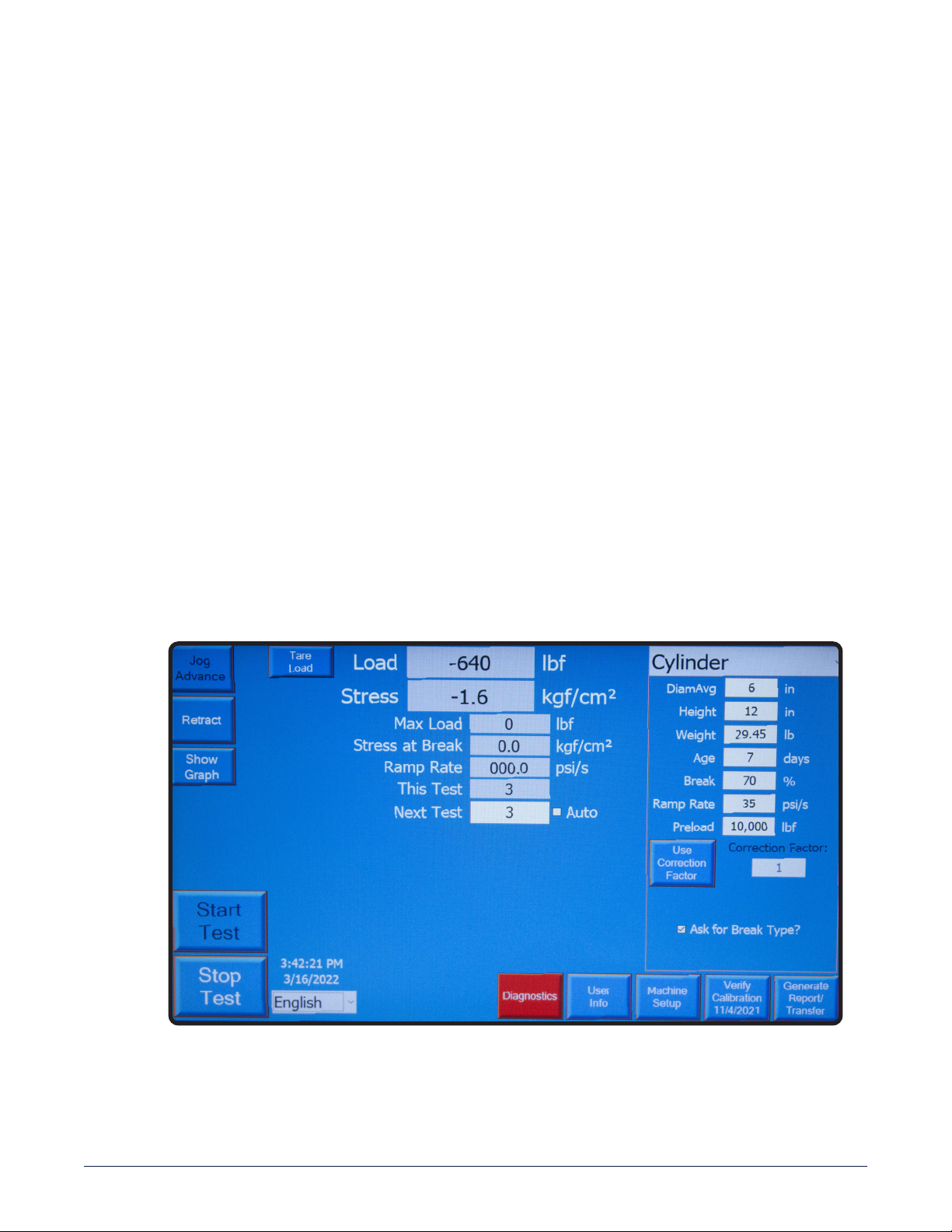
6.1 Main Test/Run Screen
The “Main Test/Run” Screen is the base screen where testing is performed. It provides access to setup, calibra-
tion, diagnostics, and reporting.