Page 3
Due to continuous product research and development,
the information contained herein is subject to change without notice.
www.stoddart.com.au
www.stoddart.co.nz
1.0 Introduction
Carefully read this instruction booklet, as it contains important advice for safe installation, operation and maintenance. Keep this
booklet on hand in a safe place for future reference by other operators or users.
Stoddart design, manufacture & distribute Food Service Equipment (appliances) exclusively for the commercial market.
This appliance is not designed nor intended for household or domestic use and must not be used for this purpose.
This product is intended for commercial use, and in line with Australian electrical safety standards the following warnings are provided:
• This product is not intended for use by persons (including children) with reduced physical, sensory or mental capabilities, or lack of
experience and knowledge, unless they have been given supervision or instruction concerning the use of the product by a person
responsible for their safety. Children should be supervised to ensure that they do not play with the product
• If the supply cord is damaged, it must be replaced by the manufacturer, its service agent or similarly qualified persons in order to avoid
a hazard
The manufacturer/distributor cannot be held responsible or liable for any injuries or damages of any kind that occur to persons, units or
others, due to abuse and misuse of this unit in regards to installation, removal, operation, servicing or maintenance, or lack of conformity
with the instructions indicated in this documentation.
Disclaimer
All units made by the manufacturer/distributor are delivered assembled, where possible, and ready to install. Any installation, removal,
servicing, maintenance and access or removal of any parts, panels or safety barriers that is not permitted, does not comply in
accordance to this documentation, or not performed by a TRAINED AND AUTHORISED SPECIALIST will result in the
IMMEDIATE LOSS OF THE WARRANTY.
The manufacturer/distributor cannot be held responsible or liable for any unauthorised modifications or repairs. All modifications or
repairs must be approved by the manufacturer/distributor in writing before initiating. All modifications or repairs performed to this unit
must be performed at all times by a TRAINED AND AUTHORISED SPECIALIST.
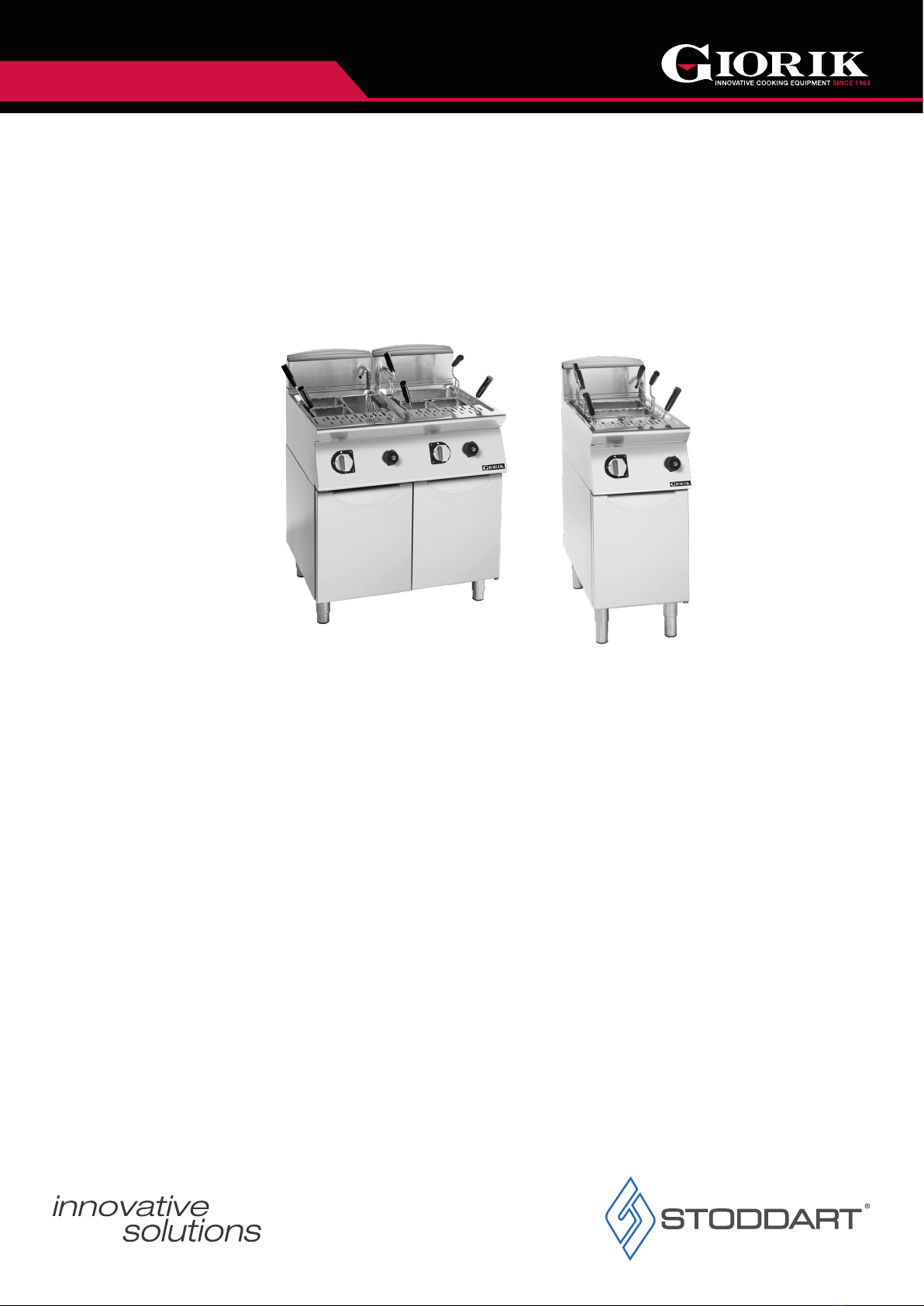
Thank you for choosing this quality Giorik product.
All Giorik products are designed and manufactured to meet the needs of food service professionals. By caring for and maintaining this new
Giorik product in accordance with these instructions, will provide many years of reliable service.
Stoddart is a wholly Australian owned company, which manufactures and/or distributes a comprehensive range of food service equipment for
kitchens, food preparation and presentation. Stoddart products are manufactured and engineered to provide excellent results whilst offering
value-for-money, ease-of-use and reliability.
1.1 Your New Giorik Product
To register your new product, Follow the below Link/QR code.
www.stoddart.com.au/warranty-information
All Stoddart manufactured and distributed products are covered by Stoddart’s standard Australia and New Zealand Product Warranty (minimum
12 month on-site parts and labour, terms and conditions apply). Further to this standard warranty, certain products have access to an extended
warranty. Full terms, conditions and exclusions can be found using the below Link/QR code.
Warranty & Registration