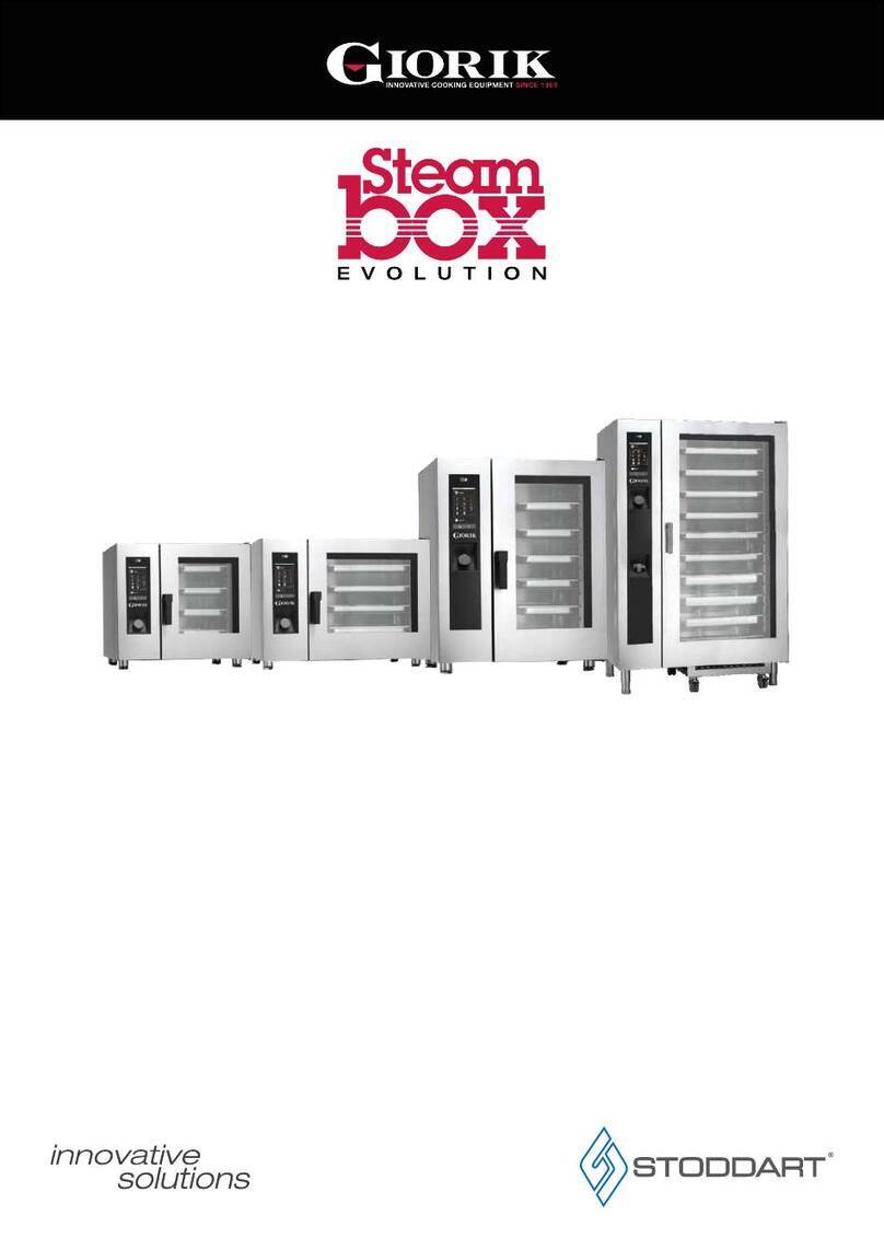
Giorik STEAM BOX SBPE061 User manual

Installation, use and
maintenance manual
COMBINED, CONVECTION AND STEAM
SBPE061 SBPE101 SBPE102 SBPE201 SBPE202
SBPG061 SBPG101 SBPG102 SBPG201 SBPG202

2
Dear Customer,
We thank you for having purchased our product.
This oven is part of a line of appliances specically designed for baking and patisserie, made of gas and
electric ovens with different capacities. The pleasant and modern design of these ovens encloses ease of use,
ergonomics and cooking control.
The oven has a 12 months warranty against any manufacturing faults, starting from the date on the sales
invoice. The warranty covers the normal functioning of the oven and does not include the consumption materials
(lights, gaskets, etc.) and faults caused by incorrect installation, wear, maintenance, repair, decalcication and
cleaning, tampering and improper use.
The manufacturer reserves the right at any time to make improving or necessary amendments to the product.
Table of Contents
4. Components for
control and safety 28
4.1. Solenoid valve 28
4.2. Door magnetic micro-switch 28
4.3. Motor thermal protection 28
4.4. Safety thermostat
of the cooking compartment 28
4.5. Flame control 28
5. What to do if 29
5.1. Common problems 29
5.2. Checks to be carried out only
by an authorised technician 29
5.3. Spare parts management 29
6. Specifications 32
6.1. Technical data 32
7. Installation layouts 33
7.1. Mod. SBPE061 33
7.2. Mod. SBPG061 34
7.3. Mod. SBPE101/SBPE102 35
7.4. Mod. SBPG101/SBPG102 36
7.5. Mod. SBPE201 37
7.6. Mod. SBPG201 38
7.5. Mod. SBPE202 39
7.5. Mod. SBPE202 40
8. Alarms description 41
8. Control panel 43
1. Installation 3
1.1. General and safety warnings 3
1.2. Positioning 4
1.3. Adjustment of hinges and
closing pin of the door 5
1.4. Water connection 6
1.4. Drain connection 6
1.6. Electric connection 7
1.7. Gas connection 9
1.8. Fumes exhaust 10
1.9. Oven start-up and testing 12
2. Use instructions 13
2.1. Preliminary information 13
2.2. Convection cooking 14
2.3. Convection/steam combi cooking 15
2.4 Steam cooking 16
2.5. Pre-heating 17
2.6. Core cooking 18
2.7. Cooking with ΔT19
2.8. Programming 20
2.9. Cooling 22
2.10. Draining valve 23
2.11. Washing 24
2.11. ESC Key 25
3. Maintenance 26
3.1. Cleaning 26
3.2. Humidity draining 27
3.3. Glass cleaning 27
3.4. Cleaning of air lter 27

3
STEAM-BOX. installation, use and maintenance manual
1. Installation
1.1. General and safety warnings
Carefully read this manual before installing
and commissioning the oven, in that the text
gives important indications regarding the safe
installation, operating and maintenance of the
equipment.
Keep this manual in a safe and easily accessible
place for further consultation by the operators.
In case of transferring the oven, always attach
the manual; if necessary, a new copy must be
requested from the authorised dealer or directly
from the manufacturing company.
Once unpacked, ensure the oven is intact and
does not show signs of damage due to transport.
A damaged appliance must never be installed and
commissioned; if in doubt, immediately contact
the after-sales technical assistance or your own
dealer.
Installation, extraordinary maintenance and
repair operations on the equipment must only be
carried out by professionally qualied staff and by
following the manufacturer instructions.
The appliance has been designed to cook food
in closed premises and must only be used for
this purpose: any other different use must,
therefore, be avoided as considered improper and
dangerous.
The oven must only be used by staff adequately
trained for its use. To avoid the risk of accidents or
damages to the appliance, it is also fundamental
that staff regularly receive precise instructions
regarding safety.
The oven must not be used by persons with
reduced physical, sensorial or mental capacities
or by persons without experience and knowledge,
unless supervised or educated regarding the
operating of the appliance by a person responsible
for their safety.
Children must be supervised to assure they do not
play with the appliance or use it.
Pay attention to the hot parts of the external
surfaces of the equipment during functioning that,
in working conditions, may exceed 60°C.
In case of fault or bad functioning, the equipment
must be deactivated; in case of repair, contact
only an after-sales technical assistance centre
authorised by the manufacturer and request
original spare parts.
Do not position other heat sources like, for
example, fryers or hotplates, near the oven.
Do not deposit or use ammable substances near
the equipment.
In case of prolonged disuse of the appliance, both
the water and electric energy supply must be
shut-off.
Before commissioning the equipment, ensure
to have removed all packaging, being careful to
dispose of it in compliance with the Standard in
force.
Every amendment to oven installation that should
result necessary, must be approved and carried
out by authorised technical staff.
Amendments to the oven wiring are not admitted.
The non-compliance with the above warnings can
jeopardise the safety of the equipment and yours.
4
fig. 1
The gas oven versions are compliant with essential requisites of Gas Directive 2009/142/EEC and are,
therefore, provided with CE review certication issued by a Notied body. They satisfy the prescriptions of the
following gas Standards:
EN 203 + subsequent updates;
EN 437 + subsequent updates.
For installation the safety prescriptions contained in the following must be complied with:
Standards UNI CIG n. 7222-7723-8723 + subsequent updates.
The equipment is compliant with the essential requisites of Low Voltage Directive 73/23/EEC and 2006/95/EEC.
It
satises the prescriptions of the following electrical Standards:
EN 60335-1 + subsequent updates;
EN 60335-2-42 + subsequent updates;
EN 55104 / EN 55014 + subsequent updates;
EN 61000 + subsequent updates.
The equipment is compliant with the essential requisites of Electro-magnetic Compatibility Directive.
1.2. Positioning
The appliances have been designed for installation in closed premises, they cannot be used in the open air
and cannot be exposed to rain.
The place of installation of the oven must have a solid, at and horizontal surface able to safely support both
the mass weight of the appliance/support and that of maximum load capacity.
The appliance must be placed in adequately ventilated premises.
1. Installation
1.1. General and safety warnings
The oven must only be installed on a stable support.
The appliance must be removed from its packaging,
its integrity checked and arranged in the place of
use, being careful not to position it above or against
walls, sides, partition walls, kitchen cabinets or
covers in ammable material.
We recommend scrupulously complying with the
reproof Standard in force.
There must be a minimum distance of 50 mm
on all sides between the oven and the walls or other
equipment. We recommend leaving 500 mm of
space between the left side of the oven and the
corresponding room wall (fig. 1), for easy oven
installation and its subsequent maintenance.

5
STEAM-BOX. installation, use and maintenance manual
All materials used for packaging are compatible
with the environment; they must be safely kept and
disposed of according to the Standard in force.
The oven must be levelled: to regulate the height of
the adjustable feet act, using as reference a spirit
level, as shown in fig. 2.
Signicant unevenness or inclinations can negatively
inuence the functioning of the oven.
Slowly remove all protective lm from the appliance
external panels, being careful not to leave traces of
adhesive.
Check that the heat disposal or inlet slots and
openings are not obstructed.
1. Installation
1.2. Positioning
1.3. Adjustment of the hinges and closing pin of the door
Once the oven has been correctly positioned in its
designated place for installation, check the closing
and seal of the gaskets on the oven compartment
door.
The door hinges must be adjusted to assure maximum
seal of the oven door during its functioning. It is
possible to adjust both the upper and lower hinges.
If required, to adjust the door seal, loosen the bolt
(fig. 3) and move the door in wanted position. Once
adjusted, fasten the bolt again.
The door's closing pin can be adjusted both in height
and in depth to eliminate any steam emissions during
cooking.
To adjust the position of the door's closing pin,
loosen the bolt (fig. 4) and move the pin in wanted
position (high/low); it is also possible to tighten the
pin to increase door pressure against the gasket or
loosen the pin to decrease it. Once adjusted, fasten
the bolt again ensuring to have positioned the lock
closing anchoring downwards.
fig. 3
fig. 2
fig. 4

6
1. Installation
1.4. Water connection
The water pressure must be max. (250 KPa) 2.5 bar.
Should the water pressure from the mains be higher
than such value, install a pressure reducer upstream
of the oven.
The minimum water temperature for the correct
functioning of the oven must be higher than 0.5 bar.
The oven has a softened water inlet (fig. 5). Always
install a water softener to bring the hardness of the
water at appliance inlet within the values of between
8° and 10° F.
Before connecting, let sufcient amount of water
ow to clean the duct from any iron residues. Check
that the lter of the solenoid valve is clean (see
paragraph 5.2).
Connect the "Water" duct to the specic cold water
mains and interpose a shut-off cock.
Ensure the shut-off cock is located in a place and in
a manner to be easily activated at any moment by
the operator.
Attention: in case of water drain pipe fault, it must be
replaced with a new one and the old and faulty one
must never be re-used.
fig. 5
1.5. Drain connection
The oven is equipped with a water draining device;
such device is located at the bottom in the rear part
of the appliance and has two tubes with a 28 mm
diameter.
Connect the tube that protrudes from the draining
device (fig. 6, ref. A). The draining device is a
siphon; we recommend connecting the tube on an
open funnel.
Check that the internal siphon is full of water and, if
not, ll it by introducing H2O through the drain in the
cooking compartment.
fig. 6
A

7
STEAM-BOX. installation, use and maintenance manual
1. Installation
1.6. Electric connection
The electric system, as prescribed and specied
by the Standard in force, must be equipped with
an efcient ground. It is possible to guarantee the
electric safety of the appliance only in the presence
of Standard electric system.
Before carrying out the electric connection, the
voltage and frequency values of the mains must
be checked to verify they are compliant with the
appliance requirements indicated on the technical
plate (fig. 7).
For direct connection to the mains it is necessary
to interpose a device between the equipment and
the same mains, dimensioned depending on the
load, that ensures its disconnection and which
contacts have an opening distance enabling the
full disconnection in the conditions of over-voltage
category III, in compliance with the installation
regulations; this device also must be located in a
place and in a manner to be easily accessible at any
moment by the operator.
Bring the main switch, to which the power supply
cable plug will be connected, in position 0 (zero).
Have professionally qualied staff check that the
plug cables' section is adequate to the power
absorbed by the appliance.
Loosen the screws xing the left side of the oven and
extract it (fig. 8).
fig. 7
The exible cable must be made of polychloroprene or synthetic elastomer under equivalent oil-resistant sheath.
Use a cable with adequate section to the load corresponding to every appliance, as shown in the table (tab. 1).
tab. 1
fig. 8
POWER SUPPLY
TOT. POWER kW
OVEN POWER kW
MOD NR
BOILER POWER kW
3N 400V AC 50 HZ
10,0
P04E
000000/01/08
11,0 IP
SBHE061
11.4
1.0
Models SBPE061 SBPG061 SBPE101 SBPG101 SBPE102 SBPG102 SBPE201 SBPG201 SBPE202 SBPG202
Voltage 3N 400V 1N 230V 3N 400V 1N 230V 3N 400V 1N 230V 3N 400V 1N 230V 3N 400V 1N 230V
Frequency (Hz) 50 50 50 50 50 50 50 50 50 50
Absorbed power (kW)
10.4 12+0.4 15.7 19+0.7 25.8 28+0.8 30.8 38+0.8 51.6 56+1.6
Cable section
power supply (mm2)5 x 2.5 3 x 1.5 5 x 4 3 x 1.5 5 x 6 3 x 1.5 5 x 10 3 x 1.5 5 x 10 3 x 1.5

8
1. Installation
1.6. Electric connection
For the electric connection, refer to the electric
layouts in the appendix to this manual.
Place the power supply cable inside the cable gland
hole in the lower part, on the left of the oven.
Connect the cable to the terminal board following the
indications in tab. 2.
Lock the cable with the cable gland.
The power supply voltage with machine functioning,
must not be different from the nominal voltage value
of ±10%.
The equipment must be included in an equipotential
system which efciency must be checked according
to that reported in the Standard in force. For the
connection there is a clamp, located on the frame
and marked with the symbol of fig. 9, to which a
cable with minimum section of 10 mm must be
connected.
For gas ovens, complete gas connection to the
appliance before assembling the oven side again; for
electric ovens assemble the oven side.
fig. 9
Electric ovens Gas ovens
L1 L2 L3 N L N
Between phase and
there must be a
potential difference of
230 V.
tab. 2

9
STEAM-BOX. installation, use and maintenance manual
1. Installation
1.7. Gas connection (only for gas ovens)
Nota bene
The oven is originally calibrated for functioning with
the gas type specied during ordering.
The type of gas for which the oven is adjusted
is reported on the technical plate found on the
appliance (fig. 10, ref. A).
During testing, ascertain the factory
calibrations carried out on the burners are
appropriate for the specific installation type,
by means of analysis of the gases produced
by combustion (CO2and CO) and check of the
thermal capacity.
Specically, with oven functioning at full capacity,
the values of the undiluted CO present during
draining, must be within 1000 ppm. If the presence
of undiluted CO over such limit is detected, the
adjustment of the burners must be checked by a
technician authorised by the manufacturer, who
will make all due amendments to the devices
governing combustion and to the relative parameters.
The detected data must be recorded and become
integrating part of the technical documentation of
that appliance.
fig. 10
Installation prescriptions
The oven installation and commissioning operations must be carried out only by qualied staff according to
regulations and Standards in force.
The gas systems, the electric connections and the installation premises of the appliances must be compliant
with regulations and Standards in force.
Bear in mind that the air necessary for combustion of the burners is of 2 m3/h per kW of installed power.
In activities open to the public, the Standards for the safety prevention of accidents and re and panic must
be complied with.
The connection to the gas supply tting can be carried out using exible metal piping, interposing an approved
shut-off cock in an easily accessible point.
Ensure that the exible metal connection tube to the gas inlet tting does not touch overheated parts of the
oven and that it is not submitted to torsion or extension stresses.
Use securing clips compliant with installation Standards.
Checks to be carried out before installation
On the technical plate located on the left side of the oven (fig. 10, ref. A) check that the appliance has been
tested for the type of gas available with the user.
Check the data on the technical plate (fig. 10) that the pressure reducer capacity is sufcient for powering
the equipment.
Avoid interposing section reductions between the reducer and the appliance.
We recommend mounting a gas lter upstream of the pressure regulator to guarantee optimal oven functioning.
A

10
Connect the oven to the gas supply system by
means of special G 3/4” tube with internal section of
not less than 20 mm of diameter (fig. 11).
Envision cocks or gates having an internal diameter
of not less than the above-said tting tube.
After gas connection, check there are no leaks on the
joints and ttings. For this purpose, use soapy water
or a specic foamy product to detect leaks.
It is opportune for the routine maintenance
of the gas ovens to be carried out yearly, in
compliance with specific Standards, by an
authorised technician; during which the fuel
gas will be analysed and the thermal power
checked.
1. Installation
1.7. Gas connection (only for gas ovens)
fig. 11
1.8. Fumes exhaust
In compliance with installation Standards, the ovens must be started in premises suitable for evacuation of
the combustion products.
It is possible to connect the ue passage in two
ways.
By means of connection to a natural duct, like
an efcient natural draught ue to evacuate
combustion products directly to the outside
(fig. 12). The continuation happens towards
the outside or to a ue by means of a conveyor.
Such intervention must guarantee evacuation of
the fumes happens without obstructions and/or
excessive length of the draining tube (maximum 3
m).
fig. 12

11
STEAM-BOX. installation, use and maintenance manual
By means of a forced evacuation system, like a
hood equipped with mechanical extractor fan.
In this case, the gas supply to the appliance
must be directly controlled by such system and
must interrupt should capacity drop below the
prescribed values. When the appliance is installed
underneath the extractor hood, check that the
following indications are complied with:
a) the extracted volume must be above that of
the generated fuel gas (see Standard in force);
b) the material with which the hood lter is made
must resist the fuel gas temperature that, at
conveyor outlet, can reach 300°C;
c) the end of the evacuation duct of the appliance
must be positioned inside the projection of the
hood base perimeter;
d) the re-admission of the gas to the appliance
must only be possible manually (fig. 13).
1. Installation
1.8. Fumes exhaust
fig. 13

12
1. Installation
1.9. Oven start-up and testing
Before commissioning the oven, scrupulously carry out the necessary checks to ensure the compliance of the
systems and installation of the appliance with the legal Standards and technical and safety indications in this
manual.
The following points must also be satised:
The ambient temperature of the place of installation of the oven must be higher than +4° C.
The cooking compartment must be empty.
All packaging must be fully removed, including the protective lm applied on the oven walls.
The air vents and louvers must be open and not obstructed.
The eventually dismantled oven pieces must be, for installation purposes, re-mounted.
The main electric switch must be closed and the water and gas shut-off cocks upstream of the appliance
must be open.
Testing
The oven test is carried out by completing a sample cooking cycle enabling to check the correct functioning
of the appliance and the absence of anomalies or problems.
Switch on the oven via the main switch T1 (g. 1).
Set a cooking cycle with temperature at 150°C, time at 10 min. and humidity at 5%/min.
Press the T16 “Start/Stop” key (g. 1).
Scrupulously check the following list:
The lights inside the cooking compartment switch-on by pressing the appropriate key and, after 45 seconds,
unless switched off by pressing the key again, automatically switch-off.
The oven stops if the door is opened and starts working again when the door is closed.
The adjustment thermostat of the temperature inside the cooking compartment intervenes upon reaching
of the set temperature and the heating element(s) is/are temporarily switched off; the intervention of the
thermostat is indicated by the temporary switch-off of LED L2 (g. 1) on the oven's control panel.
The fan(s) motor performs automatic inversion of the rotary direction; inversion happens every 3 minutes.
In ovens with two fans in cooking compartment, the motors have the same rotary direction.
Verify the leaking of water towards the fan of the humidity input tube in cooking compartment.
Once cooking cycle is completed, the oven emits a sound warning signal that lasts about 15 seconds.
IMPORTANT
In case of blockage of the procedures during the setting of the cooking phases, or to solve any other blockages
of the control panel, press, even more than once, the T13 key (g. 1).
The panel resets itself and the D1 (g. 1) display only shows the current temperature of the cooking chamber.

13
STEAM-BOX. installation, use and maintenance manual
2. Use instructions
2.1. Preliminary information
The appliance has been designed to cook food in closed premises and must only be used for this purpose:
any other different use must, therefore, be avoided as considered improper and dangerous.
Survey the equipment during functioning.
Before cooking, we recommend pre-heating the oven at a temperature of about +30°/+40°C higher
than that required.
Once it has been connected to the
mains, the oven is in “stand-by” condition
(waiting) and the D5 and D6 displays (g.
14) respectively indicate current hour and
minutes.
The oven control panel is equipped with
a knob M(g. 14) to perform the insertion
and modication of the functioning
parameters of the appliance. Such knob
can also be pressed to select a function
or conrm a certain parameter. The knob
acts on a digital encoder and, therefore,
is in continuous rotation (no end run). The
parameters adjusted by the encoder vary
clockwise increasingly.
In the stand-by condition, by pressing the
T1 key (g. 14) one switches to the “on”
condition after board reset (a few seconds):
the D1 display (g. 14) indicates the
temperature in the cooking chamber and
the oven is ready to receive the cooking
settings.
D1
fig. 14
8 9 0
845
3084
8888
8
8
8888
30
M
T1
D5
T13
T16
D6
L2
D1

14
2. Use instructions
2.2. Manual setting - convection cooking
Once the oven has been switched on by pressing the T1 key (g. 15), select the convection cooking
modality by pressing the T2 key (g. 15). Activate the desired cooking temperature setting by pressing
the T6 key, signalled by the ashing of the L2 led: set the temperature value by acting on the Mknob (up
to 300°C) and conrm the selection by pressing the T6 key or the Mknob of the encoder. The display
automatically passes to the selection of the cooking time (the L4 led ashes).
Set the cooking time by acting on the M
knob and conrm the selection by pressing
the T8 key or the Mknob of the encoder.
The display automatically passes to the
selection of the fan speed (the L5 led
ashes).
Set the fan rotation speed (there are 6
available speeds) and conrm the selection
by pressing the T9 key or the Mknob of the
encoder.
Press the T16 Start key to start cooking.
fig. 15
8 9 0
845
3084
8888
8
8
8888
30
M
T1
T2
L2
L4
T9
L5
T16
T6
T8

15
STEAM-BOX. installation, use and maintenance manual
2. Use instructions
2.3. Manual setting - convection/steam mixed cooking
Once the oven has been switched on by pressing the T1 key (g. 16), select the convection/steam
mixed cooking modality by pressing the T3 key. Activate the desired cooking temperature setting by
pressing the T6 key, signalled by the ashing of the L2 led: set the temperature value by acting on the
Mknob (up to 270 °C) and conrm the selection by pressing the T6 key or the Mknob of the encoder.
The display automatically passes to the selection of the cooking time (the L4 led ashes).
Set the cooking time by acting on the M
knob and conrm the selection by pressing
the T8 key or the Mknob of the encoder.
The display automatically passes to the
humidity selection in the cooking chamber
(the L6 led ashes).
Set the humidity value by acting on the
Mknob (value setting with a 5% step)
and conrm the selection by pressing the
T10 key or the Mknob of the encoder.
The display automatically passes to the
selection of the fan speed (the L5 led
ashes).
Set the fan rotation speed (there are 6
available speeds) and conrm the selection
by pressing the T9 key or the Mknob of the
encoder.
Press the T16 Start key to start cooking.
fig. 16
8 9 0
845
3084
8888
8
8
8888
M
T1
T3
L2
L4
L6
L5
T10
T9
T16
T6
T8

16
2. Use instructions
2.4. Manual setting - steam cooking
Once the oven has been switched on by pressing the T1 key (g. 17), select the steam cooking modality
by pressing the T4 key. Activate the desired cooking temperature setting by pressing the T6 key,
signalled by the ashing of the L2 led: set the temperature value by acting on the Mknob (the default
value is 100°C, maximum 120°C) and conrm the selection by pressing the T6 key or the Mknob of
the encoder. The display automatically passes to the selection of the cooking time (the L4 led ashes).
Set the cooking time by acting on the M
knob and conrm the selection by pressing
the T8 key or the Mknob of the encoder.
Press the T16 Start key to start cooking.
fig. 17
1 2 0
845
6084
8888
8
8888
8
M
T1
T4
L2
L4
L6
T10
T16
T6
T8

17
STEAM-BOX. installation, use and maintenance manual
2. Use instructions
2.5. Pre-heating of the cooking chamber
Once the oven has been switched on by pressing the T1 key (g. 18), select the desired cooking
modality by pressing the relative key (T2 - T3 - T4).
Activate the pre-heating of the cooking chamber by keeping the T6 Temperature function key pressed
and then pressing the used cooking modality key at the same time (for ex. T3).
The activation of the pre-heating is signalled by the ashing of the active cooking modality led.
When cooking starts the pre-heating is
signalled by the D2 display.
fig. 18
888
Pe
8888
888
M
T3
D2
T6

18
2. Use instructions
2.6. Cooking in Core mode
Once the oven has been switched on by pressing the T1 key (g. 19), select the desired cooking
modality by pressing the relative key (T2 - T3 - T4).
Select the Core mode by pressing the T7 key. Select the desired temperature value at the heat of
the product by acting on the Mknob (IMPORTANT NOTE when the core temperature value varies
the cooking chamber temperature setting, that must be at least 5°C higher, varies as well). Conrm
the selection by pressing the T7 key or the Mknob of the encoder. The display automatically passes
to the selection of the cooking chamber
temperature (the L2 led ashes).
Set the temperature value by acting on
the Mknob and conrm the selection by
pressing the T6 key or the Mknob of the
encoder.
Continue with the denition of the ulterior
cooking phase parameters according to the
chosen type of cooking.
Press the T16 Start key to start cooking.
fig. 19
1 2 0
4 58
8888
3088
M
T1
T3
T3
T4
L2
T7
T16
T6
L3

19
STEAM-BOX. installation, use and maintenance manual
2. Use instructions
2.6. Cooking in ΔT mode
Once the oven has been switched on by pressing the T1 key (g. 20), select the desired cooking
modality by pressing the relative key (T2 - T3 - T4).
Select the ΔT mode by pressing the T5 key. Set the the desired temperature difference between the
heart of the product and the cooking chamber by acting on the knob M. Conrm the selection by
pressing the T5 key or the Mknob of the encoder. The display automatically passes to the selection of
the core temperature (the L3 led ashes).
Set the temperature value at the heart of
the product by acting on the Mknob and
conrm the selection by pressing the T7
key or the Mknob of the encoder.
Continue with the denition of the ulterior
cooking phase parameters according to the
chosen type of cooking.
Press the T16 Start key to start cooking.
fig. 20
4 0
4 5
8
8
8888
3088
M
T1
T3
T3
T4
L1
L3
T16
T5
T7

20
2. Use instructions
2.7. Memorisation of the cooking programs
Every single previously illustrated cooking phase, can be memorised in order to compose a cooking program.
Once the phase setting is complete, press the T11 Phase key (g. 21). The D5 cooking phases display shows
the number of the phase, signalling its memorisation. One can therefore go on to setting the new phase, by
rotating the Mknob of the encoder. The D5 cooking phases display shows the number of the new phase, which
shall be conrmed by pressing the Mknob. It is therefore possible to go on to the insertion of the parameters of
the new phase.
Every single program can be made up of a
maximum number of 9 phases.
Once the setting of the phases of a program is
complete, this must be memorised by pressing
the T12 Book key for 3 seconds.
On the D6 display the rst available program
number appears, that can be conrmed or
modied by acting on the Mknob. The writing
MEM on the D2 display conrms the completed
memorisation of the program.
The maximum number of programs that can be
memorised is 99.
The memorised programs can be transferred
onto an external memory via the USB port
placed underneath the oven control panel (g.
22).
To import the recipes, insert the key and press
the Mknob followed by the T12 key. The D2
display (g. 21) shows .
To export the recipes, insert the key and press
the Mknob followed by the T11 key. The D2
display (g. 21) shows .
8 9 0
3084
8882
888
88
308
M
fig. 21
fig. 22
T11
T12
D5
D2
D6
This manual suits for next models
9
Table of contents
Other Giorik Commercial Food Equipment manuals

Giorik
Giorik HI LITE Owner's manual

Giorik
Giorik HI LITE Owner's manual

Giorik
Giorik Stoddart 700 Series Instruction manual

Giorik
Giorik 700 Series Instruction manual

Giorik
Giorik 700 Series User manual

Giorik
Giorik CE72TTT Instruction manual

Giorik
Giorik Steam box STODDART SEH061WT User manual

Giorik
Giorik STODDART 700 Series User manual

Giorik
Giorik 700 Series Instruction manual

Giorik
Giorik 700 Series Instruction manual