Girard Systems GG750 Installation and operating manual

Page 2 of 49
Upon receiving your shipment, it is your responsibility to check the
contents. If any product is damaged upon receipt, it is your responsibility
to refuse the shipment.
MODEL SERIAL No.
MODEL SERIAL No.
MODEL SERIAL No.
MODEL SERIAL No.
ALL ELECTRICAL WORK MUST BE CARRIED OUT BY QUALIFIED
PERSONNEL AND CONFORM TO APPLICABLE ELECTRICAL CODES
AND STANDARDS.
•Turn off power before beginning any electrical work.
•Please consult your RV’s wiring diagram to locate any wiring prior to
any drilling or any installation procedures.
WARNING
To prevent the motor from overheating do not exceed
4 minutes of operation per hour.

Page 3 of 49
•Ensure that placement of controls, cables, and wires are not in any
way obstructed. This can damage the components and obstruct
electrical current.
•Use only certified components.
Girard Systems awnings may be operated in light wind and rain
conditions. When periods of heavy rain and or high wind are expected
the awning must be closed. Never leave the awning open and
unattended.
Damage caused by wind and rain is not covered by warranty.
All awnings must be closed prior to moving the vehicle for any reason. As
an extra safety precaution a visual check that every awning is fully closed
is required.
Damage caused by failure to comply with these instructions is
not covered by warranty.
Before using your awning, ensure that the area into which the awning will
be deployed is free of obstructions (Trees, walls, pillars, posts, other
vehicles etc.)
Damage caused by collisions with any of the above or similar is
not covered by warranty.
Before using your awning make sure that all of your electrical circuits are
operating correctly.

Page 4 of 49
CONTENTS
Basic System Overview ……………………………………………………………………………........… 5
Installation Manual, Product Description ………………………………………………….............. 8
Tools Required ……………………………………………………………………………………….........… 9
Unpacking ……………….. ………………………………………………………….…………................. 9
Layout and Mounting the Brackets ………………………………………………………................11
Bracket placement chart ………………… …………………………………………....................… 12
Mounting the Awning ………………………………………………………………….…................…..15
Weather Stripping Installation (Sidewall Application) ………………………................…... 16
Electronic Controls Installation……………………………………………........…...................… 17
Rocker Switch Wiring ……………………………………………………………………….................. 17
Testing and Adjustments ……………………………………………………………….........…………. 30
Adjusting Motor Limit Switches …………………………………………….................…………… 30
Manual Override …………………………………………………………………..................………..….32
Adjusting Pitch and Elbow Height …………………………………………….……..…..................33
Testing the Motion Sensor ………………………………………………………………….................36
Adjusting the Lead Rail ……………………………………………………………………...................37
Troubleshooting Guide ………………………………………………………………………….…..........39
Common Repair Procedures ………………………………………………………………….…...........40
Motor Replacement …………………………………………………………………………..…..............40
Fabric Replacement …………………………………………………………………………….............…43
Arm Replacement ………………………………………………………………………………................45
GG 750 Exploded View …………………………………………………………………………..…..........47
Component Identification …………………………………………………………………………...........48

Page 5 of 49
BASIC SYSTEM OVERVIEW
1.
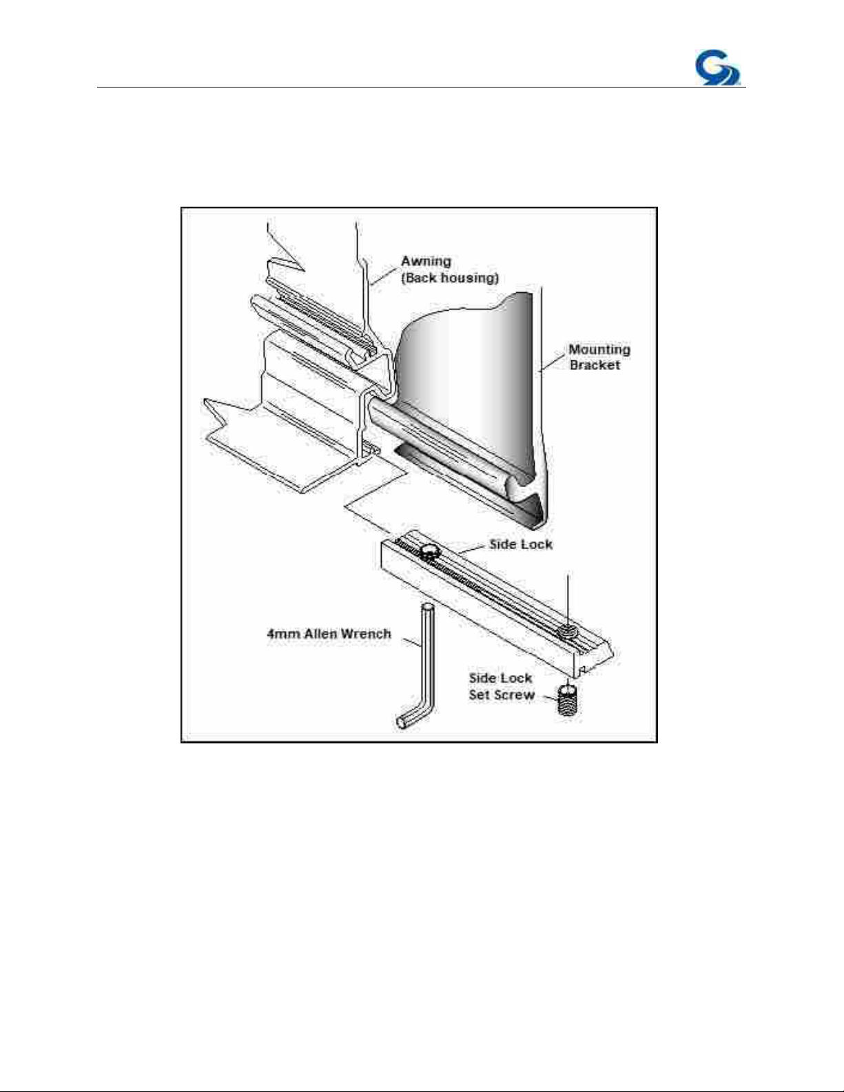
Mechanical system – consisting of:
•The enclosure (or cassette) protects the awning while closed.
•The roller tube which is mounted within the cassette.
•The top cover or fabric rolled onto the roller tube and connected to the lead
rail that extends from the enclosure when the awning is opened.
•The folding arms that supports the lead rail and the fabric.
•(Option) tubular motor which is mounted inside of the roller tube that controls
the extension and retraction of the awning.
•(Option) manual crank handle and drive system that controls the extension and
retraction of the awning
2.
Electronic controls – (Option) to power and operate the motor
•Motion Sensor – 98GC779, which enables automatic retraction of the awning
during periods of high wind that may damage the awning syste
m.
• Wired Motion Sensor – 98GC780B, Wired motion sensor that works in
conjunction with 98GC781B and 98GC783B wired wall switch controllers.
•Motor Control module – 98GC1146C. This works in conjunction with the other
electronic controls and the user controls included in the installation to extend and
retract the awning as required.
3.
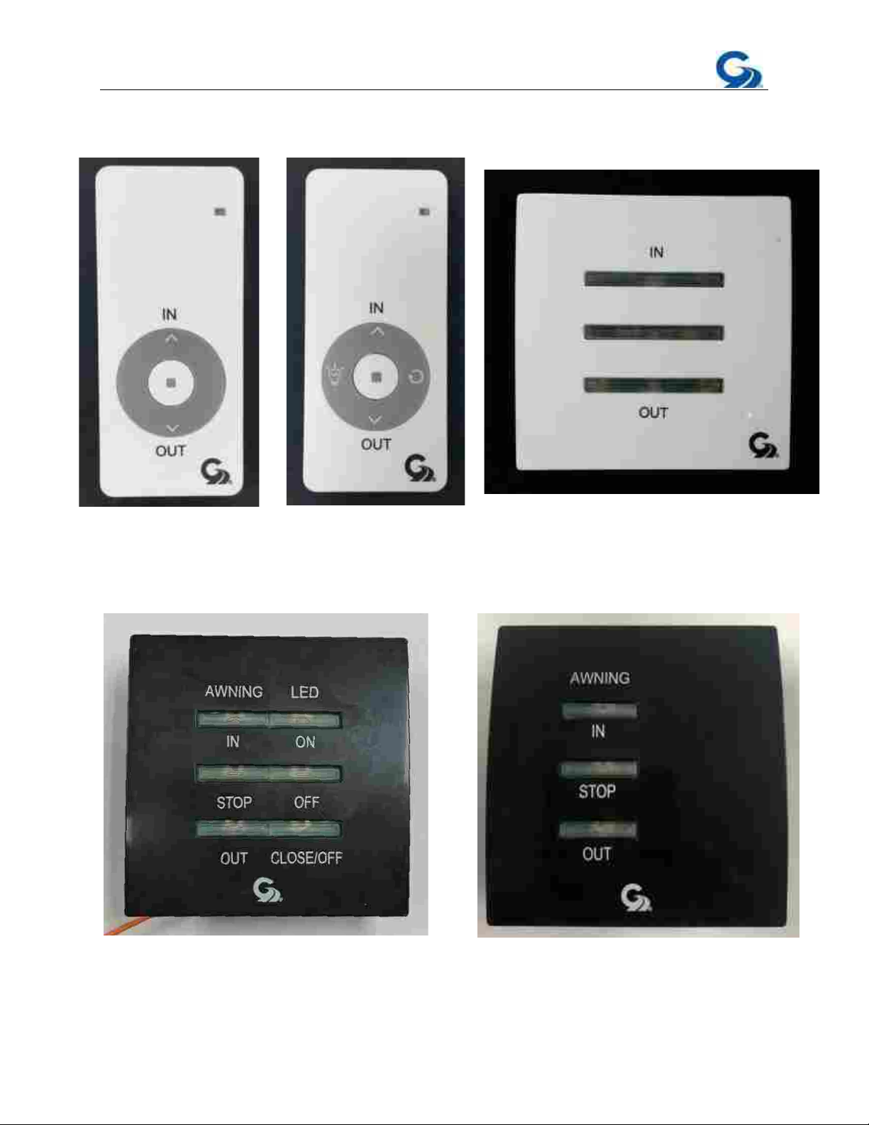
User Controls – (Option) Hand held remote controllers and wall mounted
remote switches will differ according to the individual customer’s needs, single or
multi-channel handsets, with or without LED switching facility, and wall switches
will differ depending upon how many awnings they are required to control.
•98GC104 – Single channel awning remote control
•98GC1063 – Single channel remote with LED switching
•98GC229 – Single channel remote wall switch
98GC781B – Wired wall switch controller
•
•
C783B –
8G9Wired wall switch controller
•98GGC101 – Dual Rocker Switch

Page 6 of 49
98GC779
98GC1146C
98GC780B

Page 7 of 49
98GC104
98GC1063 98GC229
98GC783B
98GC781B

Page 8 of 49
INSTALLATION MANUAL
FOR PERSONAL SAFETY AND QUALITY OF INSTALLATION, TWO
INSTALLERS ARE RECOMMENDED FOR THIS PRODUCT.
PRODUCT DESCRIPTION
The GG750 awning system provides protection from the sun at a touch of a button. The
GG750 awning is built to your specifications with the highest quality materials available,
your unit features:
•A standard 12VDC motor that operates with a wireless motor control or
rocker switch.
•Motion sensor that will retract the awning to prevent damage from the
wind.
•A hand held remote control
•A wall mounted remote switch
•Options include; electronic automation controls to ensure proper closing
at all times, a control to retract all awnings when the vehicles’ motor is
started, and more….
The GG750 awning controls use an RF (radio frequency) link to communicate with each
other. This simplifies the installation and maintenance by removing the need for
extensive wiring. This RF network is called the G-Link system. For more information
please refer to the G-Link manual that was included with your awning. All necessary
power cables are supplied with this product.
WARNING
To prevent the motor from overheating do not exceed 4 minutes
of operation per Overheating will destroy the motor.hour.

Page 9 of 49
Tools required:
•Electric Drill
GETTING STARTED
•Tape measure
•(2) ladders
•Chalk line
•Flat head screwdriver (small)
•Phillips screwdriver
•Caulking gun
•(2) tubes silicone caulking
•
Drill bits: 1/8”, 3/8”, 7/16”, 1/4”
•Allen wrenches: 4mm
•Open-end wrenches: 19mm, 17mm
•Keyhole saw
A. UNPACKING
1.
Before starting any of the installation procedures unpack the awning and
inspect the product for any possible damage that may have occurred during
shipping.
2.
Before starting any of the installation procedures ensure that the length,
fabric, and motor placement of your awning are correct.
3.
When you have determined that the product is to your satisfaction, remove
the mounting brackets and place the awning in a safe location while
preparing the RV.
a.
To remove the brackets locate the slide lock that retains the bracket to
the housing. (Figure 1)
b.
Using a 4mm Allen wrench, loosen the set screws on the slide locks.
c.
Once the set screws have been loosened the slide locks should slide
freely, clear the slide lock away from the bracket.
d.
You should now be able to remove the bracket.
4.
If you have discovered any damage or missing parts please contact your
supplier.

Page 10 of 49
(Figure 1)

Page 11 of 49
1.
SIDEWALL APPLICATION, AWNING BRACKET –NOTE: Please take into
consideration all possible clearances, and obstacles before installing
this awning. Items such as slide rooms, etc. vary from one
manufacturer to another. Please consult Girard Systems if there are
any questions regarding your installation.
a.
The mounting brackets can accommodate ¼” lag bolts for mounting.
b.
Determine the location for the final installation position of the awning, including
height to be installed.
c.
Mounting brackets must be installed at the locations shown in bracket
placement diagram (see Figure 2).
B. LAYOUT AND MOUNTING THE BRACKETS
NOTE: When installing a three arm awning, make sure one of the
applicable center brackets is directly behind the shoulder of the middle arm.

Page 12 of 49
(Figure 2)

Page 13 of 49
Failure to follow these instructions will void the warranty of this
product.
e.
Now that you have determined the bracket locations, using the bracket as your
template, mark the holes for fastening the bracket. NOTE: Use chalk line to
make absolute sure brackets are mounted in straight line.
f.
Using a 1/8” bit, pilot drill the centers of the marked holes. Inside of the RV
verify the locations of the backing plates. Note: Please consult your
RV's wiring diagram to ensure that no wiring will be damaged
while drilling the hole.
g.
Pre-drill four 1/4 inch holes per mounting bracket through the pilot holes.
h.
Apply a liberal amount of silicone caulking around each hole before installing the
brackets.
i.
Install the 2 outer brackets, and then the middle bracket(s) (if required) with four
¼ x 1 1/2" carriage bolts, washers, lock nuts and backing plate per bracket. (Figure 2)
j.
Tighten bolts and then apply silicone caulking to the top edge and both sides of
each bracket.
k.
For the motorized option, on the motor side of the awning drill a 7/16 inch hole
for the awning motor power cable to enter the RV near the electrical source.
Position the hole 4" inch from end of awning. Do not drill hole higher or lower
than the bracket. This will ensure that it will not be seen after the awning is
installed.
3.
SIDEWALL APPLICATION, AWNING RAIL MOUNTING
a.
Determine the location for the final installation position of the awning, including
height to be installed.
b.
Cut the awning rail to 6" less than the awning length.
c.
Position the awning rail on the mounting location, making sure it is level.
d.
To attach the awning to the awning rail, angle it at 90 degrees and then insert
the corresponding track on the awning into the awning rail (Figure 3).
e.
Once the awning rail is inserted, rotate the awning down so it is flush with the
mounting surface and resting against it.
f.
Open the awning to allow access to the inside of the main housing.

Page 14 of 49
g.
Use 1 lag screw and washer every 16" to secure the bottom of the awning to
the vehicle, drilling through the back of the awning housing and into the vehicle
(Figure 3).
(Figure 3)

Page 15 of 49
C. MOUNTING THE AWNING.
1.
Lift the awning into position for fastening to the vehicle mounted brackets.
a.
Ladders are usually sufficient; however, a scaffold or forklift may be used.
b.
If using a forklift use all necessary caution to protect the surface of the
awning. Lift from the center of the awning to maintain product balance
while elevating.
2.
Place the awning onto the brackets while feeding the motor power cable through
the hole. A small amount of lubricant may aid the feeding of the cable. Make
sure the grooves of the awning are securely engaged into the channels on the
bracket. (Figure 4)
(Figure 4)
3.
Secure the awning by moving the slide locks along the bottom awning track until
they are located under their respective brackets (Figure 5). The final position of the
slide lock should be directly under the shoulder of the arm.

Page 16 of 49
(Figure 5)
4.
Once the final location of the slide locks has been achieved, tighten both set screws
on each slide lock with a 4mm Allen wrench (Figure 6). This secures the awning in
place.
(Figure 6)
(OPTIONAL, WEATHER STRIPPING NOT INCLUDED, SIDEWALL
APPLICATION ONLY)
1.
Trim weather stripping to the length of the awning and remove any overhang.
2.
Make a small cut in the weather stripping to allow for the motor cord.
3.
Apply generous beads of silicone along the weather stripping.
4.
Push weather stripping firmly into place.
5.
Wipe off excess silicone.

Page 17 of 49
D. ELECTRONIC CONTROLS INSTALLATION
A. Rocker Switch Wiring
The rocker switch is wired according to Figure 8.
(Figure 8)

Page 18 of 49
B. GC1146C DC Motor Controller Wiring
Wiring Diagram
NOTE: The larger (18) gauge red/black wire
coming out of the control box is the incoming
power. The smaller (22) gauge red/black wire
is the LED outgoing power.

Page 19 of 49
C. Motion Sensor (98GC779G) and LED Connections
4 conductor power supply

Page 20 of 49
Programming the Motion Sensor (98GC779G)
Preparation for Pairing
Remove the 2 small
Phillips screws which
secure the motion
sensor to the
awning.
Fig.1
Then turn it over.
Fig.2
NOTE: All electronic kits shipped from the factory are preprogrammed and do
not require programming. This section is intended for reprogramming if
required.
Table of contents
Other Girard Systems Accessories manuals
Popular Accessories manuals by other brands

Dini Argeo
Dini Argeo 3590ET Technical manual

PERSONAL COOLING SYSTEMS
PERSONAL COOLING SYSTEMS Comfort Cooler user manual

Hukseflux
Hukseflux FHF05SC Series user manual

Fiamma
Fiamma Privacy Room CS LIGHT 255 Installation and usage instructions

Schwaiger
Schwaiger HSA400 532 instructions

Hank
Hank HKZW-MS08 user manual

Hama
Hama 00108140 manual

Zephyr
Zephyr Duct Cover Extension Z1C-00LL installation instructions

Orion
Orion OR-200W user manual

PCB Piezotronics
PCB Piezotronics M119B12/PCS-8 Installation and operating manual

AERASGARD
AERASGARD RLQ-W Operating Instructions, Mounting & Installation

optris
optris CSmicro LT15 Operator's manual