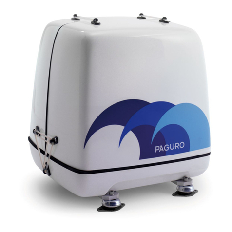
Volpi Tecno Energia PAGURO 12500 User manual

V.T.E. S.R.L.
VOLPI TECNO ENERGIA S.R.L.
Via Petronio, 1/c
34015 Muggia - Trieste
Tel.: +39 040 231715
Fax: +39 040 231933
Cap. Soc.: EUR 100.000,00 i.v.
V.A.T.: IT 00664600327
C.c.i.a.a. Trieste: 91536
E-mail: info@volpitecno.com
Web-site: www.volpitecno.com
OWNERS MANUAL
PAGURO 12500
MARINE DIESEL GENERATOR

OWNERS MANUAL V.T.E. S.r.l.
PAGURO 12500
2

V.T.E. S.r.l. OWNERS MANUAL
PAGURO 12500
3
We thank you for the confidence you have shown in us, by purchasing the PAGURO for fitting in your boat.
The target of our design, to achieve a diesel unit with the power usually supplied in a small flat, in a compact size and
light weight, is completely reached. So there is not the need to waste a large room in your boat, and even if the
chosen place is away from the centre line of the boat, the reduced weight of the PAGURO will not influence the
stability.
TECHNICAL SPECIFICATION AND PERFORMANCES
PAGURO 12500
Diesel engine maker Yanmar – Japan
Engine type / cylinders n. 3TNV88-GYM / 3 cyl.
Continuous speed (rpm) 1500 rpm
Specific fuel consumption 0.35 lt./KW/h
Cooling system Fresh water with heat exchanger
Cooling pump Johnson systemself-priming
Startingsystem 12 V Electrical starter remote controlled
Alternatormaker V.T.E. - Italy
Generator type Brushless AC synchronous generator
Cooling system Stainless steel AISI 316 L water-cooled system
Electric continuous power 50 Hz 12.5 KVA – 12 KW
Voltage 50Hz 230 V
Auxiliary voltage for starting battery 12 V - 8 A
Remote control
fitted with hourmeter, load indicator, automatic
shut off device for low oil pressure and water
over temperature, starting motor self
disengagement, 15 m cable and socket
Peak current for 2 sec. (230 V) 150 A
Noise level a 7 mtrs. 49 dB (A)
Size L x W x H, capsule included (mm) 890 x 670 x770
Weight, capsule included (kgs) 320

OWNERS MANUAL V.T.E. S.r.l.
PAGURO 12500
4
CALIFORNIA
PROPOSITION 65 WARNING
Diesel engine exhaust and some of its constituents are known to the State of
California to cause cancer, birth defects, and other reproductive harm
WARNING
Exhaust gasses contain Carbon Monoxide, an odorless and colorless gas.
Carbon Monoxide is poisonous and can cause unconsciousness and death.
Symptoms of Carbon Monoxide exposure can include:
- Dizziness
- Nausea
- Headache
- Weakness and sleepiness
- Throbbing in temples
- Muscular twitching
- Vomiting
- Inability to think coherently
IF YOU OR ANYONE ELSE EXPERIENCE ANY OF THESE SYMPTOMS GET OUT INTO
THE FRESH AIR IMMEDIATELY. If symptoms persist, seek medical attention. Shut
down the unit and do not restart unit until it has been inspected and repaired.

V.T.E. S.r.l. OWNERS MANUAL
PAGURO 12500
5
SAFETY INSTRUCTIONS
INTRODUCTION
Read these safety instructions carefully. Most accidents
are caused by failure to follow fundamental rules and
precautions. Know when dangerous conditions exist and
take the necessary precautions to protect yourself, your
personnel and your machinery.
The following safety instructions are in compliance with
the American Boat and Yacht Council (ABYC) standards.
PREVENT ELECTRIC SHOCK
WARNING:
Do not touch AC electrical connections while
engine is running, or when connected to shore
power. Lethal voltage is present at these
connections!
- Do not operate this machinery without electrical
enclosures and covers in place.
- Shut-off electrical power before accessing electrical
equipment.
- Use insulated mats whenever working on electrical
equipment.
- Make sure yourclothing and skin are dry,not damp
(particularly shoes) when handling electrical
equipment.
- Remove wristwatch and all jewelry when working on
electrical equipment.
- Do not connect utility shore power to vessel’s AC
circuits, except through a ship-to-shore double throw
transfer switch. Damage to vessel’s AC generator may
result if this procedure is not followed.
- Electrical shock results from handling a charged
capacitor. Discharge capacitor by shorting terminals
together with an insulated tool.
PREVENT BURNS - HOT ENGINE
WARNING:
Do not touch hot engine parts or exhaust
system components. A running engine gets very
hot!
WARNING:
Steam can cause injury or death!
- In case of an engine overheat, allow the engine to cool
before touching the engine or checking the coolant.
PREVENT BURNS – FIRE
WARNING:
Fire cancause injury or death!
- Prevent flash fires. Do not smoke or permit flames or
sparks to occur near thefuelline, filter, fuel pump, or
other potential sources of spilled fuel or fuel vapors.
Use a suitable container to catch all fuel when
removing the fuel line or fuel filters.
- Keep the compartment and the engine / generator
clean and free of debris to minimize the chances of
fire. Wipe up all spilled fuel and engine oil.
- Be aware –diesel fuel will burn.
PREVENT BURNS – EXPLOSION
WARNING:
Explosion from fuel vapors can cause injury or
death!
- Follow re-fueling safety instructions. Keep the vessel’s
hatches closed when fueling. Open and ventilate cabin
after fueling. Checkbelow for fumes / vapor before
running the blower. Run the blower for four minutes
before starting your engine.
- All fuel vapors are highly explosive. Use extreme care
when handling and storing fuels. Storefuelin a well-
ventilated area away from spark-producing equipment
and out of the reach of children.
- Do not fill the fuel tank(s) while the engine is running.
- Shut off the fuel service valve at the engine when
servicing the fuel system. Take care in catching any
fuel that might spill. DO NOT allow any smoking, open
flames, or other sources of fire near the fuel system or
engine when servicing. Ensure proper ventilation
exists when servicing the fuel system.
- Do not alter or modify the fuel system.
- Be sure all fuel supplies have apositive shutoff valve.
- Be certain fuel line fittings are adequately tightened
and free of leaks.
- Make sure a fire extinguisher is installed nearby and is
properly maintained. Be familiar with its proper use.
Extinguishers rated ABC by the NFPA are appropriate
for all applicationsencountered in this environment.

OWNERS MANUAL V.T.E. S.r.l.
PAGURO 12500
6
ACCIDENTAL STARTING
WARNING:
Accidental starting can cause injury or death!
- Disconnect the battery cables before servicing the
engine/generator. Remove the negative lead first and
reconnect it last.
- Make certain all personnel are clear of the engine
before starting.
- Make certain all covers, guards, and hatches are re-
installed before starting the engine.
BATTERY EXPLOSION
WARNING:
Battery explosion can cause injury or death!
- Do not smoke or allow an open flame near the battery
being serviced. Lead acid batteries emit hydrogen, a
highly explosive gas, which can be ignited by electrical
arcing or by lit tobacco products. Shut off all electrical
equipment in the vicinity to prevent electrical arcing
during servicing.
- Never connect the negative (-) battery cable to the
positive (+) connection terminal of the starter
solenoid. Do not test the battery condition by shorting
the terminals together.Sparkscould ignite battery
gases or fuel vapors. Ventilate any compartment
containing batteries to prevent accumulation of
explosive gases. To avoid sparks, do not disturb the
battery charger connections while the battery is being
charged.
- Avoid contacting the terminals with tools, etc., to
prevent burns or sparks that could cause an explosion.
Remove wristwatch, rings, and any other jewelry
before handling the battery.
- Always turn the battery charger off before
disconnecting the battery connections. Remove the
negative lead first and reconnect it last when servicing
the battery.
BATTERY ACID
WARNING:
Sulfuric acid in batteries can cause severe injury
or death!
- When servicing the battery or checking the electrolyte
level, wear rubber gloves, arubber apron, andeye
protection. Batteries contain sulfuric acid which is
destructive. If it comes in contact with your skin, wash
it off at once with water. Acid may splash on the skin
or into the eyes inadvertently when removing
electrolyte caps.
TOXIC EXHAUST GASES
WARNING:
Carbon Monoxide (CO) is a deadly gas!
- Ensure that the exhaust system is adequate to expel
gases discharged from the engine. Check the exhaust
system regularly for leaks and make sure the water-
injected exhaust elbow is securely attached.
- Be sure the unit and its surroundingsare well
ventilated.
- In addition to routine inspection of the exhaust
system, install a carbon monoxide detector. Consult
your boat builder or dealer for installation of approved
detectors.
- For additional information refer to ABYC T-22
(educational information on Carbon Monoxide).
WARNING:
Carbon Monoxide (CO) is an invisible gas.
Inhalation produces flu-like symptoms, nausea
or death!
- Do not use copper tubing in diesel exhaust system.
Diesel fumes can rapidly destroy copper tubing in
exhaust systems. Exhaust sulfur causes rapid
deterioration of copper tubingresulting in
exhaust/water leakage.
- Do not install exhaust outlet where exhaust can be
drawn through portholes, vents, or air conditioners. If
the engine exhaust dischargeoutletis near the
waterline, water could enter the exhaust discharge
outlet and close or restrict the flow of exhaust. Avoid
overloading the craft.
- Although diesel engine exhaust gases are not toxic as
exhaust fumes from gasoline engines, carbon
monoxide gas is present in diesel exhaust fumes.
Some of the symptoms or signs ofcarbonmonoxide
inhalation or poisoning are:
Vomiting
Muscular twitching
Dizziness
Intense headache
Throbbingin temples
Weakness and sleepiness

V.T.E. S.r.l. OWNERS MANUAL
PAGURO 12500
7
AVOID MOVING PARTS
WARNING:
Rotating parts can cause injury or death!
- Do not service the engine while it is running. If a
situation arises in which it is absolutely necessary to
make operating adjustments, use extreme care to
avoid touching moving parts and hot exhaust system
components.
- Do not wear loose clothing or jewelry when servicing
equipment; tie back long hair and avoid wearing loose
jackets, shirts, sleeves, rings, necklaces or bracelets
that could be caught in moving parts.
- Make sure all attaching hardware is properly
tightened. Keep the protective shields and guards in
their respective places at all times.
- Do not check fluid levels while the engine is operating.
HAZARDOUS NOISE
WARNING:
High noise levels can cause hearing loss!
- Never operate an engine without its muffler installed.
- Do not run engines for long periods with their
enclosures open.
WARNING:
Do not work on machinery when you are
mentally orphysically incapacitated by fatigue!
GENERATOR INSTALLATION
Preparations to install a generator should begin with a
thorough examination of the American Boat and Yacht
Council’s (ABYC) standards. These standards are a
combination of sources including the USCG and the NFPA.
Sections of the ABYC standardsof particular interest are:
H-2 Ventilation
P-1 Exhaust Systems
E-9 DCElectrical systems
All installations mustcomply withthe Federal Code of
Regulations(FCR).
ABYC, NFPA AND USCG PUBLICATIONS FOR INSTALLING
DIESEL ENGINES
Read the following ABYC, NFPA and USCG publications for
safety codes and standards. Follow their
recommendations when installing your generator.
ABYC (AmericanBoatand Yacht Council)
Safety Standards for Small Craft
Order from:
ABYC
3069 SolomonsIslands Rd.
Edgewater, MD 21037
NFPA (National Fire Protection)
Fire Protection Standard for Motor Craft
Order from:
NFPA
11 Tracy Drive
Avon Industrial Park
Avon, MA 02322
USCG (United States Cost Guard)
USCG 33CFR183
Order from:
U.S. Government Printing Office
Washington, D.C. 20404

OWNERS MANUAL V.T.E. S.r.l.
PAGURO 12500
8
EC DECLARATION OF CONFORMITY
Manufacturer: VOLPI TECNO ENERGIA SRL
Address: Via Petronio 1/C – 34015 – Muggia (TS)
The undersigned Riccardo Snaidero as Volpi Tecno Energia general manager declares that the
generator model:
Code Model
AP125023050S0 PAGURO 12500
Corresponds to the requirements ofthe following EEC Directives:
- 89/392/EEC (as amended by the Directive 91/368/EEC and 93/44/EEC)
- 89/336/EEC (as amended by the Directive 92/31/EEC)
- 73/23/EEC (as amended by 93/68/EEC)
Volpi Tecno Energia
Riccardo Snaidero
General Manager

V.T.E. S.r.l. OWNERS MANUAL
PAGURO 12500
9
TABLE OF CONTENTS
GENERAL INFORMATIONS …………………………………………………………………………………………………………………………….... 3
SAFETY INSTRUCTIONS ………………………………………………………………………………………………………………………………. 5
INTRODUCTIONS / RECOMISSIONINGS ……………………………………………………………………………………………………………… 9
1. INSTALLATION ……………………………………………………………………………………………………………………………………………….. 10
EXTERNAL CONNECTIONS ………………………………………………………………………………………………………………………………. 12
VENTILATION ……………………………………………………………………………………………………………………………………………….. 12
LOCATION AND MOUNTINGS ………………………………………………………………………………………………………………………………. 13
FUEL LINES (Fuel Supply Line, Fuel return Line) …………………………………………………………………………………………..... 13
EXHAUST SYSTEM ………………………………………………………………………………………………………………………………………………… 14
RAW WATER COOLING SYSTEM (Siphon break, Raw Water Intake) …………………………………………………………… 15
STARTING BATTERY CONNECTION ………………………………………………………………………………………………………………. 16
MAIN OUTPUT VOLTAGE (230 V AC) ………………………………………………………………………………………………………………. 17
CONTROL PANEL ………………………………………………………………………………………………………………………………………………… 17
2. PREPARATION FOR INITIAL START-UP ………………………………………………………………………………………………………………. 18
DIESEL FUEL ………………………………………………………………………………………………………………………………………………… 18
ENGINE OIL SPECIFICATION ……………………………………………………………………………………………………………………………….. 18
PRE-START INSPECTION ……………………………………………………………………………………………………………………………….. 18
3. STARTING/STOPPING PROCEDURE ………………………………………………………………………………………………………………. 19
ELECTRIC START ………………………………………………………………………………………………………………………………………………… 19
PRE-HEATING ………………………………………………………………………………………………………………………………………………… 19
STARTING OPERATION ……………………………………………………………………………………………………………………………….. 19
OPERATING THE GENERATOR ……………………………………………………………………………………………………………………………….. 19
INITIAL START UP CHECKLIST ……………………………………………………………………………………………………………………………….. 19
STOPPING THE GENERATOR ……………………………………………………………………………………………………………………………….. 19
4. BREAK-IN PROCEDURE ……………………………………………………………………………………………………………………………….. 20
CHECK LIST ………………………………………………………………………………………………………………………………………………… 20
STOPPING THE GENERATOR ……………………………………………………………………………………………………………………………….. 20
5. MAINTENANCE SCHEDULE ……………………………………………………………………………………………………………………………….. 21
6. EXHAUST SYSTEM ………………………………………………………………………………………………………………………………………………… 22
EXHAUST SYSTEM PRECAUTIONS ………………………………………………………………………………………………………………. 23
7. COOLING SYSTEM ………………………………………………………………………………………………………………………………………………… 24
RAW WATER PUMP (inspecting/changing the raw water pump impeller) …………………………………………………………… 24
RAW WATER INTAKE STRAINER ……………………………………………………………………………………………………………………………….. 24
DRAINING THECOOLING SYSTEM ………………………………………………………………………………………………………………. 24
8. LUBRICATION SYSTEM ……………………………………………………………………………………………………………………………….. 24
ENGINE OIL ………………………………………………………………………………………………………………………………………………… 25
OILPRESSURE ………………………………………………………………………………………………………………………………………………… 25
OILCOOLER ………………………………………………………………………………………………………………………………………………… 25
OIL FILTER (Replacing the oil Filter) ………………………………………………………………………………………………………………. 25
CHECKING THE OIL ………………………………………………………………………………………………………………………………………………… 25
CHANGING THE OIL ………………………………………………………………………………………………………………………………………………… 25
DRAINING THE USED OIL ……………………………………………………………………………………………………………………………….. 25
ADDING NEW OIL ………………………………………………………………………………………………………………………………………………… 25
9. FUEL SYSTEM ………………………………………………………………………………………………………………………………………………... 25
DIESEL FUEL ………………………………………………………………………………………………………………………………………………… 25
FUEL ADDITIVES ………………………………………………………………………………………………………………………………………………… 25
CAREOF THE FUEL SUPPLY ……………………………………………………………………………………………………………………………….. 25
FUEL LIFT PUMP ………………………………………………………………………………………………………………………………………………… 25
FUEL FILTER (Replacing the Fuel filter) ………………………………………………………………………………………………………………. 25
FUEL SUPPLY LINE ………………………………………………………………………………………………………………………………………………... 26
FUEL FILTER OF THE WATER-SEPARATING TYPE ……………………………………………………………………………………………... 26
FUEL INJECTION PUMP ……………………………………………………………………………………………………………………………….. 26
FUEL SHUT-OFF SOLENOID ……………………………………………………………………………………………………………………………….. 26
BLEEDING THE FUEL SYSTEM ……………………………………………………………………………………………………………………………….. 26
SPARE PARTS ………………………………………………………………………………………………………………………………………………... 26
10. DC ELECTRICAL SYSTEM ……………………………………………………………………………………………………………………………….. 27
CONTROL PANEL ………………………………………………………………………………………………………………………………………………… 28
12 VOLT DC CONTROL CIRCUIT ……………………………………………………………………………………………………………………………….. 28
BATTERY (Battery Care, Checking the service Battery) ……………………………………………………………………………………………… 28
11. GENERATOR INFORMATION ……………………………………………………………………………………………………………………………….. 29
REQUIRED OPERATING SPEED ……………………………………………………………………………………………………………………………….. 29
GENERATOR MAINTENANCE ……………………………………………………………………………………………………………………………….. 29
12. GENERATOR TROUBLESHOOTING ………………………………………………………………………………………………………………. 29
13. SHORE POWER TRANSFER SWITCH ………………………………………………………………………………………………………………. 30
14. LAY UP AND RECOMISSIONING ……………………………………………………………………………………………………………………………….. 31
NOTE ……………………………………………………………………………………………………………………………………………………………....... 33

OWNERS MANUAL V.T.E. S.r.l.
PAGURO 12500
10
INSTALLATION
When installing PAGURO generators, it is important that strict attention be paid to the
following information:
CODES AND REGULATIONS
Federal regulations, ABYC guidelines and safety codes must be complied with when
installing generators in a marine environment.
SIPHON-BREAK
For installation where the external shock absorbers close to or will be below the vessel’s
waterline, provisions must be looped a minimum of 50 cm above the vessel’s waterline.
Failure to use a siphon-break when the external shock absorbers are at or below the
load waterline will result in raw water damage to the engine and possible flooding of
the boat.
If you have any doubt about the position of the external shock absorbers relative to the
vessel’s waterline under any of the vessel’s various operating conditions or when the
vessel is not underway, install a siphon-break. This precaution is necessary to protect
your engine.
NOTE: A siphon-break requires periodic inspections and cleaning to ensure proper
operation. Failure to properly maintain a siphon-break can result in catastrophic engine
damage. Consult the siphon-break manufacturerfor a proper maintenance schedule.
EXHAUST SYSTEM
The exhaust hose must be certified for marine use. The system must be designed to
prevent water from entering the exhaust under any sea conditions and at any angle of
the vessel’s use.

V.T.E. S.r.l. OWNERS MANUAL
PAGURO 12500
11
1. INSTALLATION
The following factors should be considered when planning the installation of your PAGURO generator:
1. Size and weight of the generator.
2. Generator location and mounting surface.
3. Ventilation.
4. Exhaust system.
5. Fuel supply and return.
6. Raw water inlet and outlet (through exhaust system).
7. Oil fill and oil drain hose.
8. Electrical connections.
9. Maintenance and service accessibility.
10. Accessories.
Refer to the following illustration for the generator's overalldimensions.
Generator dimensions

OWNERS MANUAL V.T.E. S.r.l.
PAGURO 12500
12
EXTERNAL CONNECTIONS
The locations of the external connections are shown on the followingillustration. The various linesshould be of the specified
gauges/diameters, not only to avoid loosening or leakage, but also because using the correct sizes will prevent unnecessary
gaps in the sound-shield that could emit noise.
External connections
DIAMETERS:
Water inlet: 1’’ x 27 mm
Exhaust system: 60 mm
Fuel in: 8 mm
Fuel return: 8 mm
Siphon break: 27 mm
Battery positive: 35 mm2
Battery negative: 35 mm2
Main out put voltage: 16mm2
VENTILATION
Allow for the sufficient intake of cool air for proper engine combustion and the discharge of the heated air while the
generator is running. Since heated air rises, the intake of cool air should be directed into the lower area of the generator
compartment and the heated air should be discharged from the upper area of the compartment. Minimum clearancesof the
generator’s sound-shield hood from the generator compartment’s bulkheads are shown in the illustration. These are the
minimum clearances required to provide adequate ventilation.
NOTE: Engine combustion air enters the generator’s enclosure through holes in the base of the enclosure. This area
must be kept clear of obstructions to help insure air entry.

V.T.E. S.r.l. OWNERS MANUAL
PAGURO 12500
13
Minimum Clearance
LOCATION AND MOUNTING
A solid, levelmountingplatform is very important for the proper operation of yourgenerator. Selecta location that will allow
adequate space on all sides forventilation and servicing. Locate the generator away from living quartersand away from bilge
splash and vapors.
The mounting platform may be of wood, metal or fiberglass. It must be horizontal and should be as small as possible to
minimize vibrations. A low mounting platform is preferred because it will be stable and easy to build; a higher mounting
platform must be very sturdy to avoid resonance and vibrations (see illustrations).
A further solution to increase the dampening of vibrations is adding a plate between the generator and the boat's mounting
platform. This will also improve the sound insulation. For this plate not less than 3 cm thick wood and soft mounts. Position
these mounts one on each corner (see illustration). Mount the plate to the boat's platform, then mount the generator to the
plate.
Generatormounting
FUEL LINES
Fuel supply line
In most installations, thegeneratorwould use the same fuel tank as the vessel's propulsion engine.If this is the case, the fuel
supply line to the generator should come from its own pick-up in the common fuel tank and not tee off the supply line to the
propulsion engine. To assure proper suction, the generator's fuel pump should not be more than 1 m above the bottom of
the fuel pick-up tube.
Fuel return line
The fuel returnline at the fuel tank should be extended down to the bottom of the tankin the same manner as the fuel pick-
up tube. This must be done in an installation where the fuel tank is located below the engine's fuel system. This precaution
insures against hard starting due to air displacing fuel siphoning out of the engine's fuel system through the return line when
the generator is shut down.

OWNERS MANUAL V.T.E. S.r.l.
PAGURO 12500
14
NOTE: The injection pumpof the PAGUROis self-bleeding, it means that in case the engine shut-off forlack offuel,after fuel
tank filling up there is no need of disconnecting the pipes for bleeding, because this operation is simply obtained
acting byhand on the lever of the feeding pump.
NOTE: Even if a fuel filter is contained in the capsule, it is necessaryto install an external water/fuel separator.
EXHAUST SYSTEM
It is important to install a proper exhaust system to avoid engine flooding. The system must be designed to prevent water
from entering the exhaust line under any sea conditions and at any angle of the vessel's hull. Exhaust system failures are not
covered by V.T.E.'s warranty. The installer should have a basic knowledge ofmarine installation requirements.
V.T.E. recommends installing an exhaust system having in-line mufflers (see illustration). The in-line water-lock mufflers must
be located below the generator. It must accumulate any water that runs back down the exhaust line after the engine is shut
down. Designed the system, so there is an adequate drop in the line between the exhaust manifold and the through-hull
discharge end of the line. The exhaust hose must be certified for marine use. Use the following illustrations as ageneral guide
when installing an exhaust system.
CAUTION:
An exhaust line that is too long and/or has a poor
gradient can cause water to return back to the
generator’s engine when the generator is shut off!
WARNING:
The exhaust system must be tight and free of leaks.
Exhaust gasses are deadly. Display the Carbon
Monoxide warning decal near your generator, on
your cabin bulkhead, or in some other prominent
location.
V.T.E. presumes that the installer of this marine diesel generator is familiar with the safeguards a water-cooled marine
exhaust system will provide for the engine. Failure to design and layout a proper exhaust system can result in catastrophic
damage to the diesel engine, and possibly result in the sinking of the vessel in which the unit is installed.
Standard system:
The best noisedampingresult is obtained fittingthe 3typical exhaust mufflers:
1. the first as water-lock avoids the risk of water return into the engine and dumps 50% of noise;
2. the second reduces a further 20% noise and must be fitted with a gradient towards the out let in order to avoid
water return;
3. the third dumps a further 10% and avoids the risk of external seawater entrance due to waves.
Water-exhaust separator:it is possible to reduce the noiseof the exhaust line installing a water-exhaust separator as per the
following images. In this case, the exhaust gas output is separated from the water output, so that the typical plash of the
water (of the traditional exhaust lines) is eliminated.

V.T.E. S.r.l. OWNERS MANUAL
PAGURO 12500
15
To avoid water returns, the water-lock muffler must be installed at a lower position than the generator, so that the
connecting pipe from the generator to the water-lock muffler goes down. It is necessary that the water has a forced path in
the down direction, so when the generator is stopped the water present in the cooling circuit flows to the muffler and not to
the engine.
Please, also consider that the pipe from the generator to the water-lock muffler should be shorter as possible (but not less
than 15cm)in order toreduce the exhaust noise.
Please refer to the illustrations for the minimal/maximal length of the pipes and the location of the mufflers.
RAW WATER COOLING SYSTEM
Siphon-break
For installations where the external shock absorbers are close to or below the vessel’s waterline, provisions must be made to
install a siphon-break in the raw water supply hose to the exhaust elbow. The siphon-break provides an air vent in the raw
water cooling system to prevent raw water from filling the exhaust system and the engine’s cylinderwhen the engine is shut
down.

OWNERS MANUAL V.T.E. S.r.l.
PAGURO 12500
16
CAUTION:
Failure to use a siphon-break when the external
shock absorbers are located at or below the
waterline will result in raw water damage to the
engine and possible flooding of the boat.
If you have any doubt about the position of the external shock absorbers relative to the vessel’s various operating conditions
or when the vessel is not under way, install asiphon break. This precaution is necessary to protect your engine.
The siphon-break must be installed in the high point of a hose that is looped a minimum of 50 cm above the vessel’s
waterline. This siphon-break must always be above the waterline during all angles of vessel operation to prevent siphoning
from occurring. V.T.E. has provided two siphon-break hoses (these are tagged). The hose (27 mm diameter) to the siphon-
break connects to the raw water line at the raw water pump outlet. The hose (27 mm diameter) from the siphon-break
attaches to the oil cooler inlet. If not ordered andincluded in thegeneratorsupply, the ownermustfurnish the siphon-break,
and any additional lengths of hose that may be required.
NOTE: A siphon-break requires periodic inspections and cleaning to ensure proper operation. Failure to properly maintain a
siphon-break can result in severe engine damage. Consult the siphon-break manufacturer for a proper maintenance
schedule.
Raw water intake
A flush-type thru-hull fitting is recommendedfor the raw water intake. It should be located on the boat's hull whereit will be
below the waterline during all angles of the boat's operation.
NOTE: the sea water intake is usually designed asymmetrically, so that depending from the fitting direction can cause, when
the boat is sailing, pressure or vacuum in the water circuit connected. For a generator the water intake must be fitted
into the direction causing vacuum, because on the contrary a self water entrance can be caused when the boat is
sailing and thegenerator is not running, flooding the exhaust line with water that finally reaches the engine oil sump
causing severe damages to the engine.
STARTING BATTERY CONNECTION
The PAGURO generator is negative grounded. For electric starting install a 12V battery of 90Ah. Connect the positive (+)
battery cable to the starter solenoid where is already fitted a thin red cable and the negative (-) cable to the engine ground
stud (one of the 2 studs located on the starter where is already foreseen a metallic loop)
Please refer to the electrical scheme of this manual.
The generator's battery charger will charge its starting battery only (8A max)

V.T.E. S.r.l. OWNERS MANUAL
PAGURO 12500
17
STARTING BATTERY
MAIN OUTPUT VOLTAGE (230 V AC)
The connection of the 230V AC is located into thegrey box, located inside the capsule.
Open the grey box and connect to the connector the 230 V cables from the transfer switch present on board
(generator/shore line) to the terminal boards located inside: consider that the external terminals are the 230 V AC and the
central one is the ground.
The diameters of the cablemust be notless of 16 mm2
Please refer to the electrical drawing present on this manual.
As the most of the boats have installed 230 V (115 V) feeding line from the shore, it has to be absolutely avoided that the
shore line and the generator remain contemporaneously connected to the boat plant.
A manual switch (shore / generator) or an automatic switch (shore / generator) must be provided.
Both the lines or at least the generator line only, have to be protected with a thermic switch, fitted on the main boardpanel.
For your PAGURO choose a:
230V 50cyc.
PAGURO 12500 55A
CONTROL PANEL
Mount the plug-in control panel in any desired remote location. The panel is furnished with 15 m of cable. When installing,
pass the cable though bulkheads by disconnecting the cable at the control panel side. Refer to the following drawing for
control panel dimensions.
Control panel dimensions

OWNERS MANUAL V.T.E. S.r.l.
PAGURO 12500
18
2. PREPARATION FOR INITIAL START-UP
DIESEL FUEL
The generator is fed by diesel through the two fuel connections (fuel-in and fuel-return). Do not use kerosene or home
heating fuel.
Care of the Fuel Supply
Use only clean diesel fuel. The clearance of the components in your injection pump is very critical; invisible dirt particles
which might pass through the filter can damage these finely finished parts. It is important to buy clean fuel, and keep it clean.
The best fuel can become unsatisfactory by carelesshandling or improper storage facilities. To assure that the fuel going into
the tankfor yourengine’s daily use is clean and pure, purchase a well-known brand of fuel. Alsoinstall andregularly service a
good fuel / water separator filter between the fuel tank andthe generator.
ENGINE OIL SPECIFICATION
Select the appropriate engine oil viscosity base on the
ambient temperature and use the SAE service grade
viscosity chart in the figure.
Please refer to the engine manufacturer manual for any information.
CAUTION:
Do not allow two or more brands of engine oil to
mix. Each brand contains its own additives; additives
of different brands couldreact in the mixture to
produce properties harmful to your engine.
PRE-START INSPECTION
Before starting your engine for the first time, or after a prolonged layoff, check the following items:
Check the engine oillevel.Add oil tomaintainthe level atthe highmark on the dipstick.
Turn on the fuel supply, then check the fuel supply and examine the fuel filter / water separator bowl for contaminants.
NOTE: refer to the specifications for the proper diesel fuel and lubricating oil types and quantities.
Check the DC electrical system. Inspect wire connections and battery cable connections. Make certain the positive
(+) battery cable is connected to the starter solenoid and the negative (-) cable is connected to the engine ground
stud.
The shore power safety switch must be OFF.
The shore power transfer switch must be in the GENERATOR mode.
Open the raw water intake.
Visually examine the generator. Look for loose or missing parts, disconnected wires, and unattachedhoses. Check
the threaded connections. Check for fuel leaks.
Make sure the exhaust system is secure and all the connections are tight.
Make sure there is a good ventilation and an ample air supply. These are necessary for proper engine performance.
Make sure the mounting installation is secure.
Check load leads for correct connections as specified in the wiring diagrams.
Be sure no other generators or utility power is connectedto the load lines.
CAUTION:
When starting the generator, it is recommended
that all AC loads, especially large motors, be
switched off until the engine has come up to speed
and, in cold climates,starts to warm up. This
precaution will prevent damage caused by
unanticipated operation of the AC machinery will
prevent a cold engine from stalling.

V.T.E. S.r.l. OWNERS MANUAL
PAGURO 12500
19
3. STARTING/STOPPING PROCEDURE
CAUTION: All AC loads must be switched off
before starting. This precaution will prevent damage
caused by unanticipated operation of AC machinery
and will prevent a coldengine from stalling.
STARTING OPERATION
Keep the START button pushed, the yellow start indicator light will come onand start to blink. Once the engine fires and runs,
the yellow start indicator light will go out and the green runindicator light will come on.
NOTE: If a start attempt is aborted, the yellow indicator light will continue to blink. To reset the circuit, press the
STOP button.
Apply a light load to thegeneratorand allow the engine towarm up to operating temperature before applyingheavy
loads.
NOTE: Some unstable running may occur in a cold engine. This condition should smooth out as the engine warms up and
when the generators loads are applied.
OPERATING THE GENERATOR
After the generator has started, run it with a medium load for warm up. If possible, apply the loadin stages.
CAUTION:
Never operate the engine for long periods of time
without an amperage load being applied, otherwise
carbon build-up may occur which can cause severe
damage to the engine.
INITIAL START-UP CHECK LIST
Check for possible leaks from all the connections inside the sound-shield.
Make sure the cooling water is discharging properly, outboard from the exhaust outlet.
Make certain that the generator is mounted securely.
Listen for unusual sounds and vibrations.
STOPPING THE GENERATOR
Remove the AC loads from the generator one at a time and allow the generator to run for an additional 3 to 5 minutes (this
stabilizes its operating temperature).
To stop the generator, press the STOP button on the control panel; shutdown is automatic.
Check the lube oil level a few minutes after stopping the engine, because lube oil from the bearings etc. continues to drain
down into the oil sump. Disregarding this fact and not maintaining the proper oil level may lead to overfilling, causing
overheating and the possibility of engine runway.
After shutdown,carefully inspect the generator. Check for possible leaks from all the connections inside the sound-shield.

OWNERS MANUAL V.T.E. S.r.l.
PAGURO 12500
20
4. BREAK-IN PROCEDURE/ DAILY PROCEDURE
After the generator has been started, check for proper operation and then encourage a fast warm-up. Run the generator
between 20% to 60% of full load for the first 10 hours.
CAUTION:
Do not attempt to break-in your generator by
running without a load.
After the first 10 hours of the generator'soperation, theload can be increased to thefull-load rated output; then periodically
vary the load.
Avoid overload at all times. Anoverloadis signaledby the red LIGHTlighting located onthe remotecontrol panel, bya smoky
exhaust with reduced output voltage and frequency. Monitor the current being drawn from the generator and keepit within
the generator'srating.
To protect against unintentional overloading of the generator, the generator's output leads should be routed through a
circuit breaker that is rated at the rated output of the generator.
Note: be aware of motor starting loads and the high current drawn required for starting motors. This starting amperage
drawnis 3timesnormal running amperage. SeeGENERATOR INFORMATION in this manual.
CHECK LIST
Follow this check list each day before starting your generator.
Record the hour-meter reading in your log (engine hours relate to the maintenance schedule).
Visually inspect theengine for fuel, oil or water leaks.
Check the oil level (dipstick).
Check your diesel fuel supply.
Check the starting batteries (weekly).
Check for abnormal noise such a knocking, vibration and blow by sounds.
Confirm exhaust smoke:
When the engine is cold - White Smoke.
When the engine is warm - almost Smokeless
When the engine is overloaded - some Black Smoke
Make sure the cooling water is discharging properly, outboard from the exhaust outlet.
NOTE: Afterthe first 20hoursof generator operation,checkthe maintenance schedule for the first 20hours service check.
CAUTION:
Do not operate the generator for long periods of
time without a load being placed on the generator.
STOPPING THE GENERATOR
Remove the AC loads from the generator one at a time and allow the generator to run for an additional 3 to 5 minutes (this
stabilizes its operating temperature).
To stop the generator, press the STOP button on the control panel; shutdown is automatic.
Check the lube oil level a few minutes after stopping the engine, because lube oil from the bearings etc. continues to drain
down into the oil sump. Disregarding this fact and not maintaining the proper oil level may lead to overfilling, causing
overheating and the possibility of engine runway.
After shutdown,carefully inspect the generator. Check for possible leaks from all the connections inside the sound-shield.
Table of contents
Other Volpi Tecno Energia Inverter manuals
Popular Inverter manuals by other brands

Turing
Turing HT-E-2000-12 manual

dolycon
dolycon CT112 Series user manual

Asami
Asami AMV6 Service manual

Olimpia splendid
Olimpia splendid Unico Air 10 SF EVA Instructions for use and maintenance

Winco
Winco WL18000VE-03/A Installation & operator's manual

Voltacon
Voltacon PH5000 Series Quick installation manual