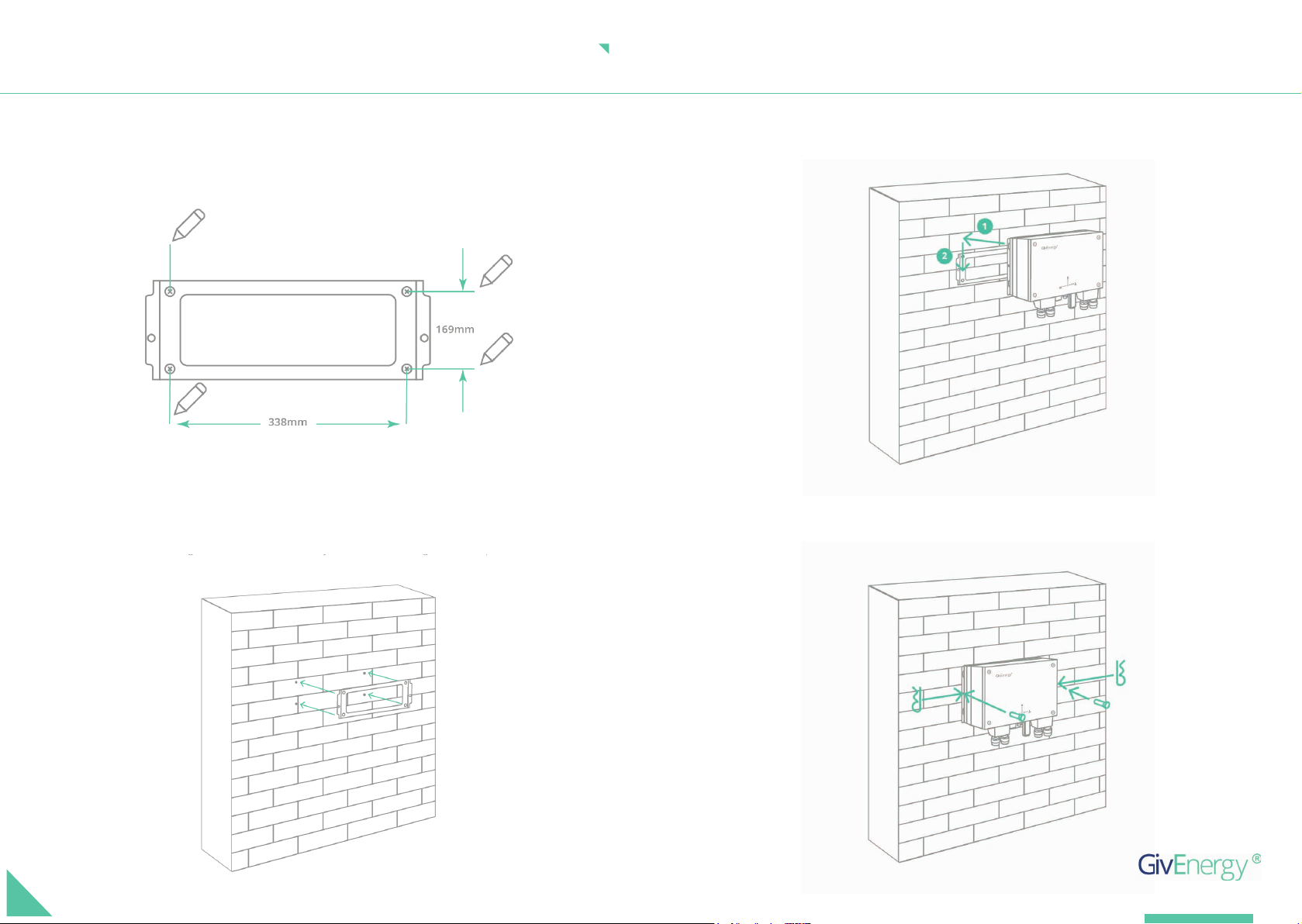
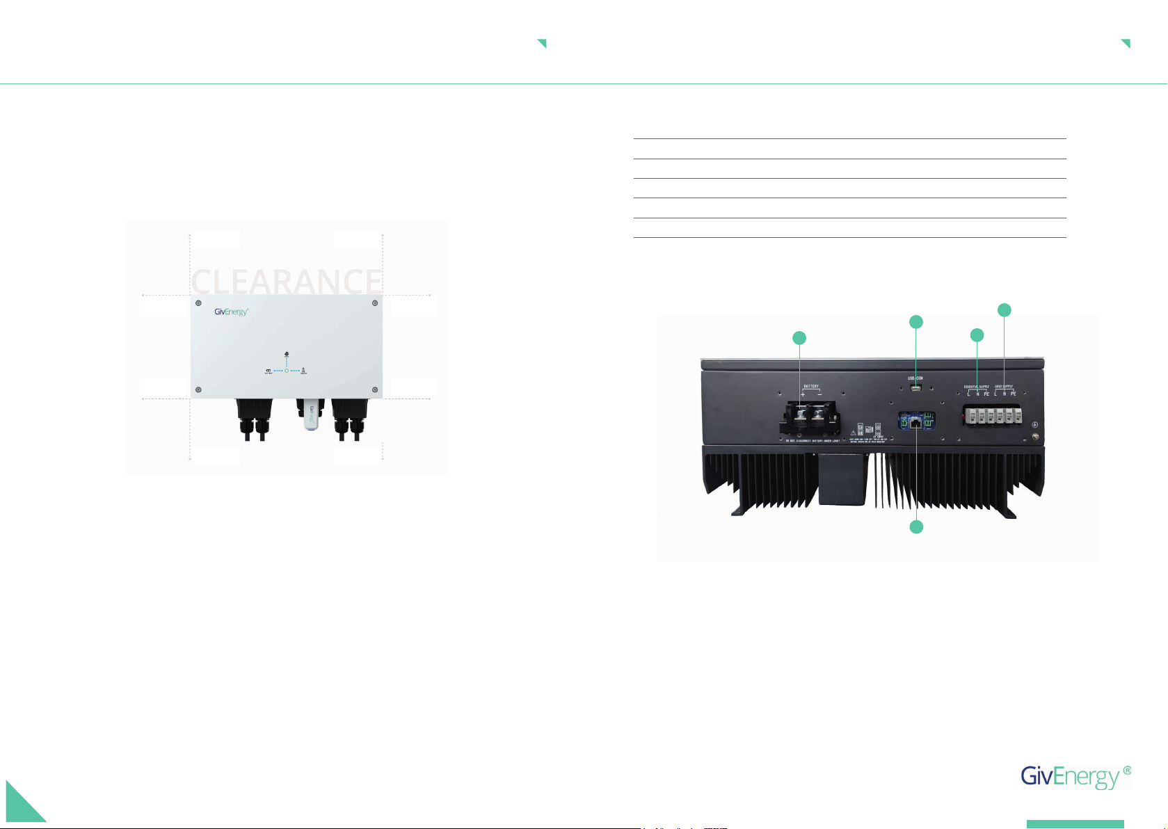
Do not install in direct sunlight or near water sources
Mount the inverter at least 3 feet above ground level (outside only)
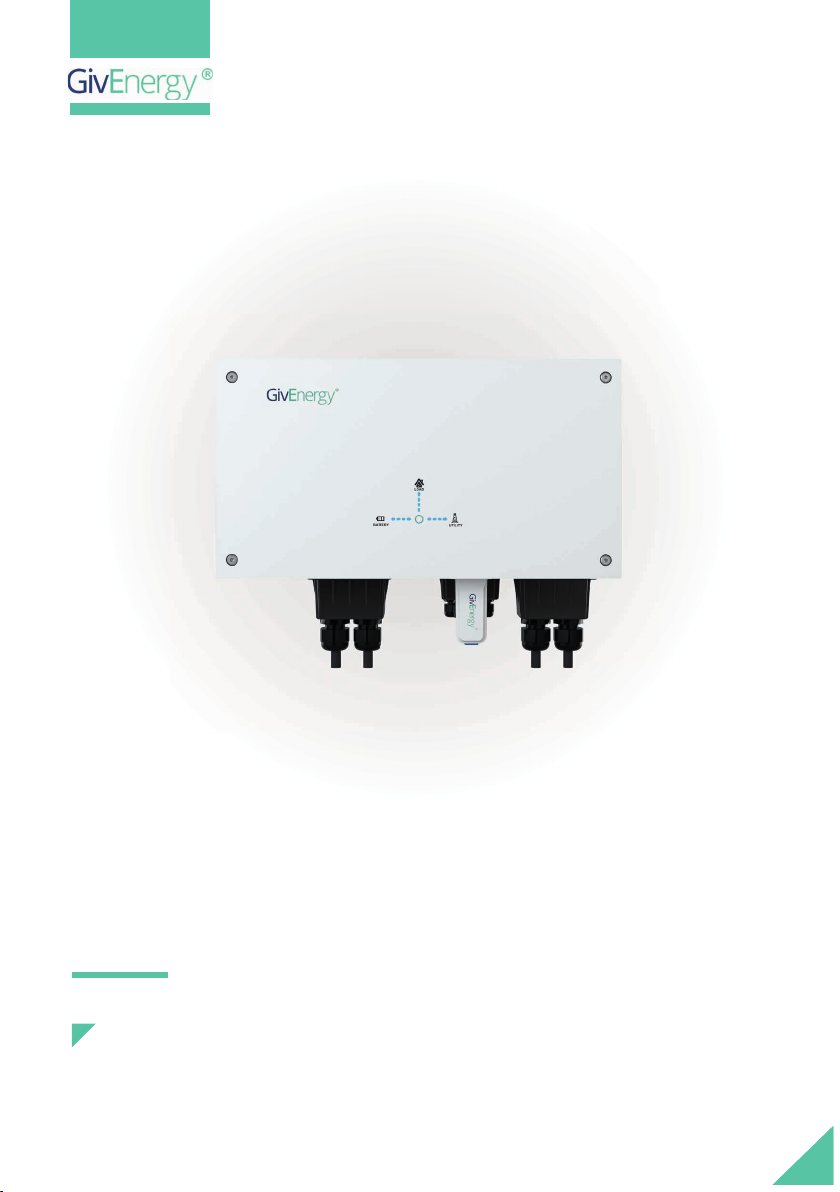
The inverter must be installed in an easily accessible location, the status display
must be visible and not obstructed
Please ensure that the wall to be mounted on is suffi cient enough to hold the weight
of the inverter and battery pack
The inverter must be installed in a well ventilated area, the ambient temperature
should be below 40ºC to ensure optimal operation
The inverter must be installed vertically with connections always positioned at the
bottom, never install horizontally, and avoid tilting the unit
Extra care and attention must be taken when installing and maintaining any GivEnergy equipment.
The system is capable of retaining a high voltage, even when disconnected.
Safety Instructions
SAFETY AND INSTALLATION
All electrical installations must be carried out by a qualifi ed and registered Electrician and in accordance
with the local wiring regulations
During operation, the heat sink may become hot. Do not touch the heat sink at the sides, or top of
the inverter when in operation
The inverter is designed to be connected to the grid; connecting your inverter to a generator or
other power source can result in damage to the inverter or external devices
All GivEnergy equipment must be installed by a GivEnergy Approved Installer
If you suspect something is wrong with the inverter, or if there are any missing/damaged parts contact
GivEnergy on 01377 252 874 or email support@givenergy.co.uk
Precautions
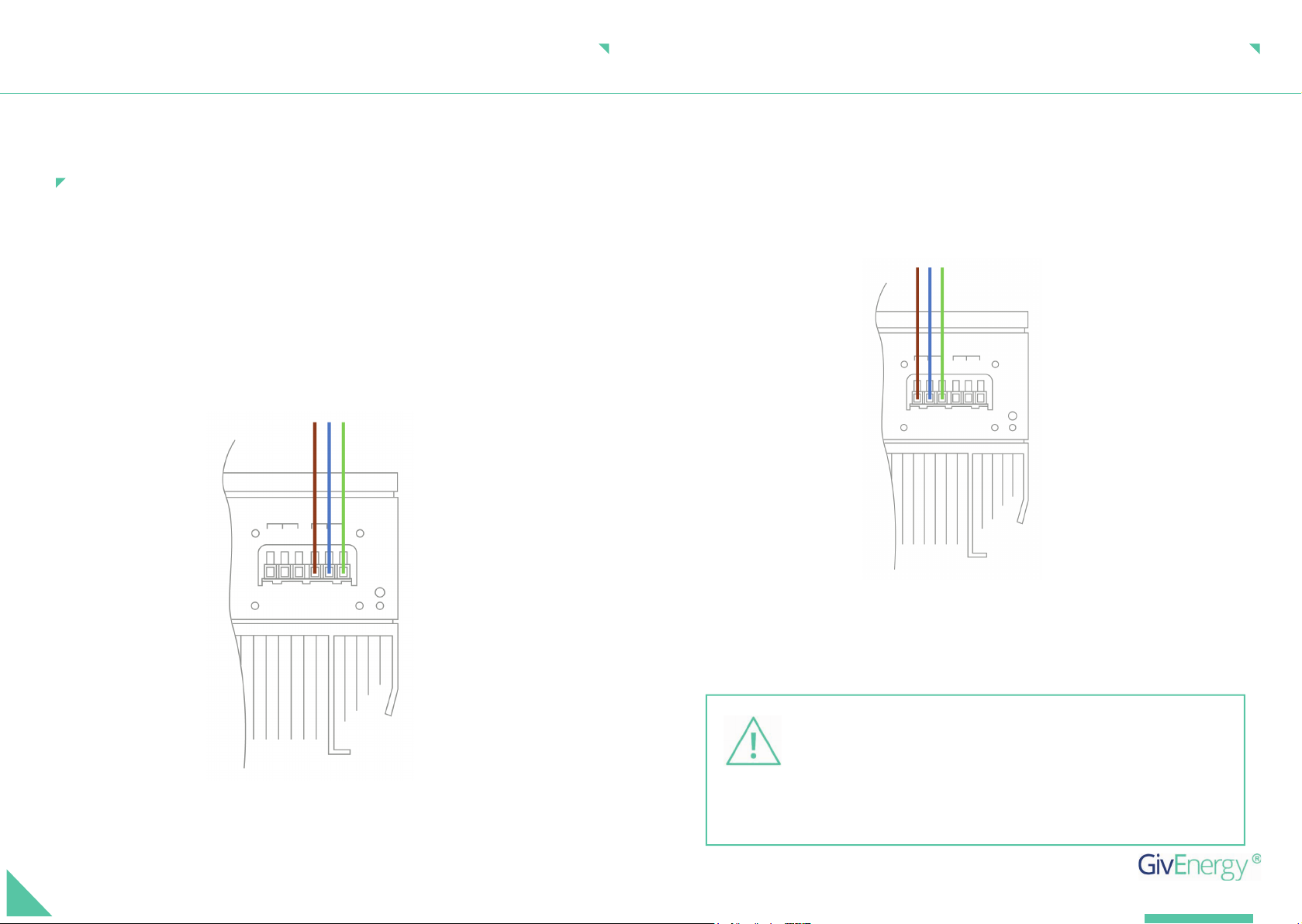
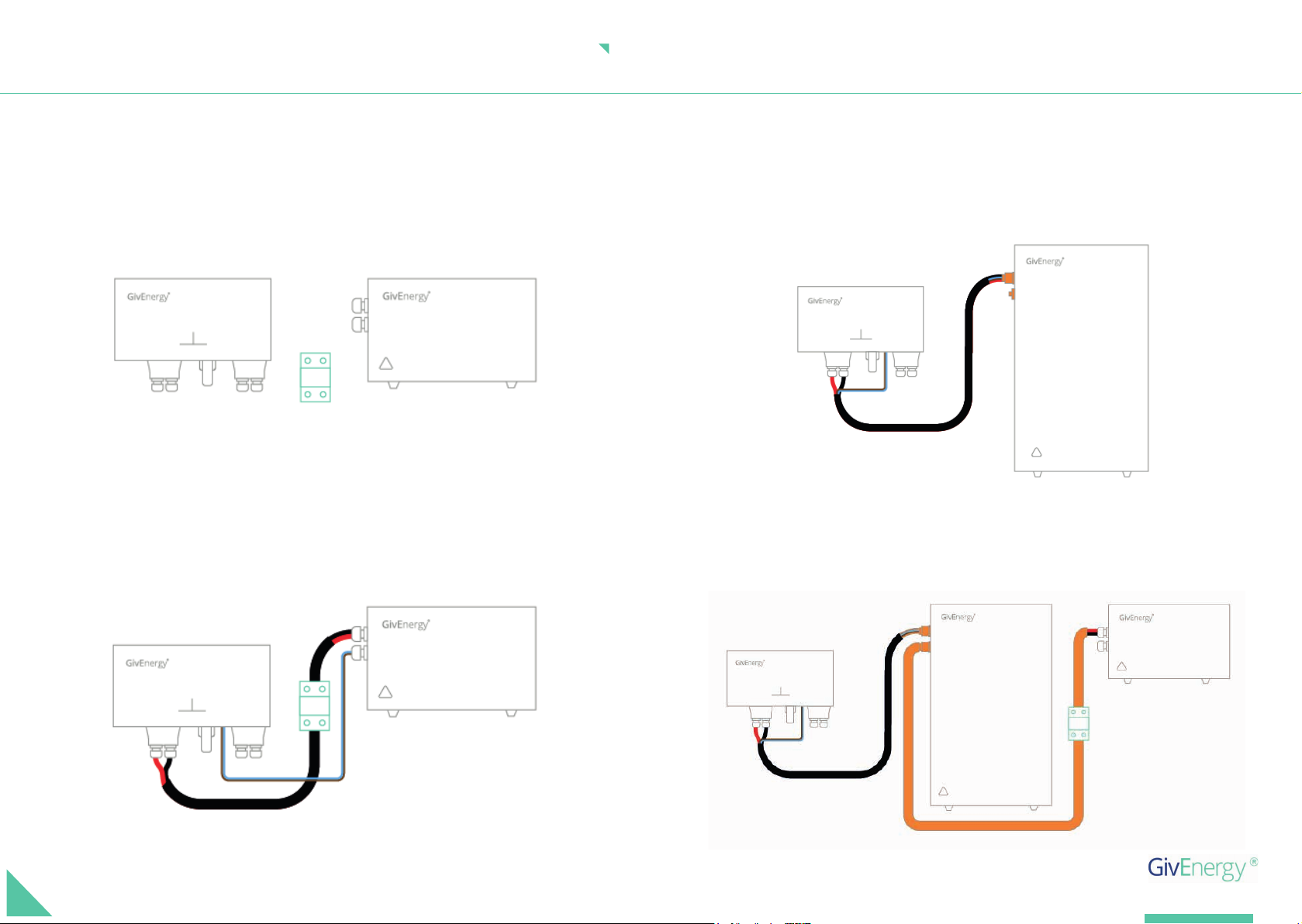
CONNECTING THE BATTERY TO THE INVERTER
It is very important for system safety and effi cient operation to use appropriate cables for battery
connections. 16mm2(minimum) tri-rated cables must be used for DC battery connections
The battery must be installed in accordance with the Battery Installation Guide
The batteries must not be connected in series
The voltage of the battery connected must not exceed 60V (or it will damage the inverter and void any
warranty)
Only GivEnergy batteries should be connected to our inverters
Reversed polarity will damage the inverter