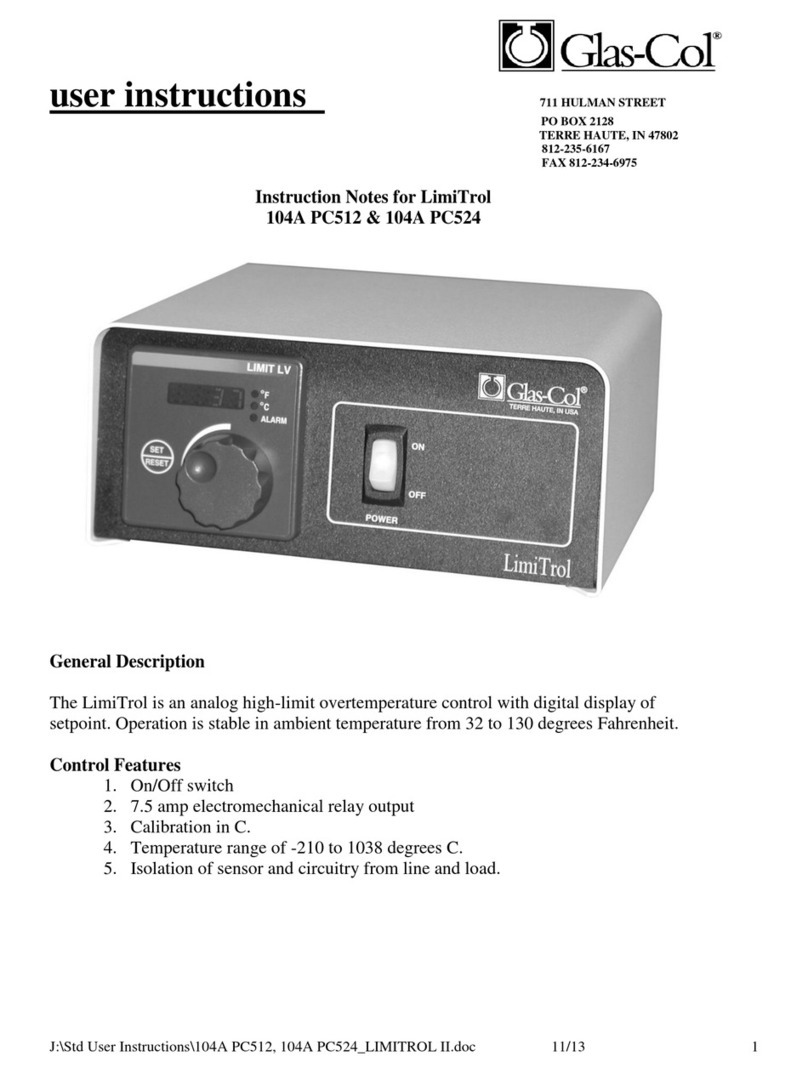
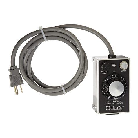
Glas-Col DigiTrol II User manual

12/22/14 1 Rev.5 (EC 02.293.435)
Operation Manual
Instruction Notes for DigiTrol II General Use Instruction Manual
General Description
This temperature control displays both the setpoint and process temperature and uses the most modern control
technology for the best temperature stability. The Auto-tune feature minimizes setpoint overshoot and learns your
process. Changing your setpoint is easily done with the interface keys. The controller can also perform ramp rate
operations to allow the user to slowly raise the process temperature. There are several input types available. This unit
comes with a 6’ detachable power cord, grid support bracket, which is ideal for fume hood mounting to maximize bench
space. This control is a microprocessor-based, digital indicating, automatic temperature control with a single input and a
single output. It features an auto-tuning function that allows automatic setting of control parameters with a minimum of
user input required. This family of control accepts a type "J", “K”, or “T” thermocouple input depending on the model
ordered.
The control automatically sets the PID parameters through a "learning" sequence in the auto-tuning mode. PID
parameters include proportional band, reset/integral and rate/derivative. User-friendly features include automatic LED
indicators to aid in monitoring and setup, as well as dual LED displays for process temperature and set point indication.
This control automatically stores all information in a non-volatile memory.,
Control Features
1. On/Off switch.
2. 15-amp output.
3. Control mode
- PID control mode (factory default) with Auto-tune algorithm.
- ON / OFF control mode programmable (user programmable).
- Manual Control Mode (user programmable)
4. Solid State Relay output.
5. Circuit protection (fuse)
6. Low profile housing.
7. Safety feature- Output is de-energized if sensing device is unplugged or damaged.

12/22/14 2 Rev.5 (EC 02.293.435)
How to Setup and Operate
First, connect the heater load and the sensor to the load and sensor receptacles on the front panel. Next, plug the control
line cord into an appropriate 3-wire grounded power receptacle. Turn the power switch to the "ON" position. Wait five
seconds for the control unit to energize.
The control is shipped from the factory with the display reading in degrees C. If a display in degrees F is desirable, press
the UP/DOWN arrow keys simultaneously for three seconds to access the Setup Page. Press the Advance key until the
Celsius_Fahrenheit parameter [C-F] is shown in the lower display. Press the UP arrow key to change from C to F.
After changing the display, press the Infinity key to display the set point temperature and the process temperature
(temperature at the sensor).
To begin the heating process, use the Up/Down arrow keys to enter the desired set point temperature. This is shown in
the lower display. Auto-tuning is recommended in all applications. Auto-tuning allows the control to set the PID
parameters without those parameters being manually entered/calculated by the user. It also minimizes the amount of
temperature overshoot of the set point and decreases the time required for the process to stabilize. See page 8 for
instruction on performing the auto-tune function.
It is recommended that the auto-tune feature be used every time the process temperature set point has been changed. If
the process is being repeated, the parameters learned in the initial setup are stored in the memory of the control and the
auto-tune process isn’t required to be repeated in most applications.

12/22/14 3 Rev.5 (EC 02.293.435)
Control Sensor
Proper placement of the sensor can eliminate many problems associated in the total operation of the system. The probe
should be placed so that it can detect any temperature change with little thermal lag. In a process that requires fairly
constant heat output, the probe should be close to the heating source. In processes where heat demand is variable, the
probe should be placed close to the work area. Experimenting with probe location should be tried to provide optimum
results for your particular process.
Specifications
Control Mode
- Microprocessor-based, single input, single output.
- PID parameters
Proportional band: 1 to 999o F
Reset: 0.00 to 99.99 repeats per minute.
Integral: 0.00 to 99.99 minutes per repeat.
Rate or Derivative: 0.00 to 9.99 minutes.
Operator Interface
- Advance, Infinity, Up and Down keys, and ON/OFF switch.
- (2) 4 character LED display.
- Thermocouple receptacle and 3 wire load receptacle.
Input
- Type J, K, and T thermocouple: Input grounded or ungrounded. (T/C type associated with the model number)
- Automatic cold junction compensation and break protection for sensor.
- Degrees F or degrees C display; user selectable (Factory set for °C)
Range Type J:
-200°C to 1200°C
Range Type K:
-200°C to 1370°C
Range Type T:
-200°C to 400°C
Primary Output (Heating or Cooling)
- 15 Amp, 120 Volts or 10 Amp, 240 Volts depending on model
Accuracy
- Calibration accuracy: 0.1% of span.
- Temperature stability: 0.2 oF /oF rise in ambient maximum.
- Voltage stability: 0.01% of span / % of rated line voltage.
Power
- 50/60 Hz 5%
- Data retention upon power failure via nonvolatile memory.
Operating Environment
- 32 to 149 oF / 0 to 65 oC; 0 to 90% RH, non-condensing.

12/22/14 4 Rev.5 (EC 02.293.435)
Control Values:
Operation Menu
Parameter Name
Glas-col value
Default
Operation Page
[AUt]
Autotune
Default
no
[C;M]
Control Mode Active
Default
AUto
[h;Pb]
Heat Proportional Band
Default
25.0 F or 14.0 C
[C;Pb]
Cool Proportional Band
Default
25.0 F or 14.0 C
[ti]
Time Integral
Default
180
[td]
Time Derivative
Default
0
[o;tb1]
Time Base Output 1
Default
1.0 or 20.0
[o;tb2]
Time Base Output 2
Default
1.0 or 20.0
[A;Lo]
Alarm Low Set Point
N/A
32.0 F or 0.0 C
[A;hi]
Alarm High Set Point
N/A
300.0 F or 150.0 C
[i;CA]
Calibration Offset
Default
0.0

12/22/14 5 Rev.5 (EC 02.293.435)
Setup Menu
Parameter
Parameter Name
Glas-col Factory Setting
Default
Setup Page
[LoC]
Lockout Menu
Default
5
[SEn]
Sensor Type
Default
tC
[Lin]
Linearization
SET FOR TC INPUT
TYPE
J
[dEC]
Decimal
Default
0
[C_F]
Display Units
C
F
[r;Lo]
Range Low
Default
0.0
[r;hi]
Range High
Max temperature for
sensor type
9,999.0
[Fn1]
Function of Output 1
Heat
oFF
[o;ty]
Output Type
Default
voLt
[Fn2]
Function of Output 2
Default
oFF
[h;Ag]
Heat Algorithm
Default
PID
[hSC]
Hysteresis (Heat & Cool)
Default
3.0 F or 2.0 C
[C;Ag]
Cool Algorithm
Default
oFF
[A;ty]
Alarm Type
Default
oFF
[A;hy]
Alarm Hysteresis
Default
1.0
[A;LA]
Alarm Latching
Default
nLAt
[A;bL]
Alarm Blocking
Default
oFF
[A;Si]
Alarm Silencing
Default
oFF
[A;dSP]
Alarm Display
Default
on
[rP]
Ramp Action
Default
oFF
[r;rt]
Ramp Rate
Default
1.0
[o;hi1]
Power Scale Output High 1
Default
100.0
[o;hi2]
Power Scale Output High 2
Default
100.0
[PAr1]
Upper or Left Display
Default
AC.Pu
[PAr2]
Lower or Right Display
Default
AC.SP
[Ad;S]
Zone Address - Standard Bus
Com
Default
1

12/22/14 6 Rev.5 (EC 02.293.435)
Control mode operation
Manual operation provides direct (time proportioned % time) control from -100% to 100%. A negative value is allowed
only when Ot 1=Cool. Automatic operation provides sensory feedback ON/OFF or PID control. When the operation
transfers from automatic to manual operation, the power level from automatic operation is retained and restored to the
previous set point.
The % LED indicates manual operation. The LED is on when in Manual operation and off when in AUTO operation.
When the LED is flashing, press the Infinity key again within 5 seconds to complete the change in operation. It the
sensor is open and LOC=0, 1 or 2, the control switches to Manual operation if the output was stable before the break
occurred.
Tuning-Automatic
It is recommended that auto-tuning be used each time a new process is initiated. If the process is being duplicated, the
parameters learned in the initial auto tune setup are stored in the memory of the control and the auto-tune procedure isn’t
required in most applications.
Auto-tuning: This control can automatically tune the PID parameters to fit the characteristics of your particular thermal
system.
Auto-tune can only be used when Output 1 setting is hEAt and heat algorithm (h.Ag, page 5) is set for PID mode. The
heat algorithm setting is set for PID from the factory. When the auto-tune sequence has started, the lower display will
flash between tun1-attn and the main operation screen.
Changing the set point, while in auto-tune mode, will not change the set point value. The displayed value will change but
the control has locked in the original set point value tell the auto tune in complete or has been turned off by the user. Once
the control has finished "learning" the system, it returns to standard PID control with the values automatically set. Auto-
tuning is complete within 80 minutes. In order for the control to successfully complete auto-tune, the process must cross
the 90% set point value four times within 80 minutes after auto-tune has started. If this does not happen within the 80
minute time limit, Pb1 remains at 0 and the control will operate with the factory default PID values.
To start auto-tuning:
1. Set the set point value with the arrow keys to the desired temperature of operation.
2. Press the Advance key until the Aut prompt appears in the lower display.
3. Change the parameter to YES with the arrow keys.
4. Press the Infinity key to display the set point and sensor temperatures. While the control is in the auto-tuning
mode, the display will alternate between the set point and the "Aut" prompt. When tuning is complete, the lower
display indicates only the set point.

12/22/14 7 Rev.5 (EC 02.293.435)
5. When tuning is complete, the lower display indicates setpoint only and Aut reverts to OFF. The control installs
appropriate PID tuning parameters and retains them in the non-volatile memory.
*To abort auto-tuning, the operator must reset Aut to OFF. Auto-tuning may also be aborted by cycling power off and on.
In all cases, aborting auto-tuning restores all original factory default values.
Temperature overshoot
In most cases this is due to a small sample size being heated with a high wattage heater. The control is set at the factory
with the Power Scale High Output 1 (o.hi1) setting with a value of 100. This value can be adjusted in the setup menu,
reference page 5 for instructions on how to access and navigate through the setup menu. If excessive temperature
overshoot is occurring, adjust the value to 50 and start the heating process from ambient room temperature. If more than
desired temperature overshoot is still occurring, decrease to a lower value and repeat heating process from ambient room
temperature. If the process temperature doesn’t achieve the set point temperature or takes more than desired amount of
time to reach set point temperature, increase the power scale high output 1 value. This process can take several value
changes to obtain proper temperature control with your particular application setup. It is recommended to initiate the Auto-
Tune process again after the proper power scale high output 1 value has been determined for your application.
Error Code Definitions and Actions
Indication
Description
Possible Causes
Corrective Action
Sensor does not provide
a valid signal to controller
Sensor improperly wired or open,
Incorrect setting or sensor type, or
Calibration corrupt
Correct wiring or replace
sensor, Match setting to
sensor , or Check
calibration of controller
Controller is auto-tuning
the control loop
User started the auto-tune function
Wait until auto-tune
completes or disable
auto-tune feature
Controller is ramping to
new set point
Ramping feature is activated
Disable ramping feature if
not required
Sensor input above high
alarm set point
Temperature is greater than alarm set
point
Over temperature, or Set
alarm source to proper
setting
GLOSSARY
Automatic prompts: Data entry points where a microprocessor-based control "prompts" or asks the operator for
information input.

12/22/14 8 Rev.5 (EC 02.293.435)
Auto-tune: Automatically tunes the parameters to fit the characteristics of your particular thermal system.
Cold junction compensation: Electronic means to compensate for the effect temperature at the cold junction.
Cycle time: The time necessary to complete a full On-through-Off period in a time proportioning control system.
Derivative/Rate: Anticipatory action that senses the rate of change of the process, and compensates to minimize
overshoot and undershoot.
Default parameters: The parameters (programmed instructions) permanently stored in microprocessor software to
provide the data base.
Droop: Difference in temperature between set point and stabilized process temperature.
Hysteresis: In On/Off control, the temperature change necessary to change the output from On to full Off.
Input (sensor): Process variable information being supplied to the instrument.
Integral/Reset: Control action that automatically eliminates offset, or "droop", between set point and actual process
temperature.
Offset: Adjustment to actual input temperature and to the temperature valves the control uses for display and control.
ON/OFF control: Control of temperature about a set point by turning the output full On below set point and full Off above
set point.
Output: Action in response to difference between set point and process variable.
Overshoot: Condition where temperature exceeds steeping due to initial power up or process changes.
Parameter: a physical property whose value determines the response of a electronic control to given inputs.
PID: Proportioning control with auto-reset and rate.
Process variable: Thermal system element to be regulated, such as time, temperature, relative humidity, etc.
Proportional band: Span of temperature about the set point where time proportional control action takes place.
Set point: Intended value of the process variable.
Thermal system: A regulated environment consisting of a heat source, heat transfer medium, sensing device and a
process variable control.
Thermocouple: Temperature sensing device that is constructed of two dissimilar metals wherein a measurable,
predicative voltage is generated corresponding to temperature.
Thermocouple break protection: Fail-safe operation that assures output shutdown upon an open thermocouple condition.
Time Proportioning Control: Action which varies the amount of ON and OFF time when "close" to the set point (within the
proportional band). This variance is proportional to the difference between the set point and the actual process
temperature.
Maintenance
Simple preventative maintenance steps include keeping the controller clean. Protect it from overload, excessive dirt, oil
and corrosion.

12/22/14 9 Rev.5 (EC 02.293.435)
Cleaning
If cleaning is necessary, using only a damp cloth with only water, wipe only the exterior of the control chassis.
Replacement Parts:
Power cord:
If the power cord supplied with the control would become missing or damaged, replace only with the appropriate rated
power cord noted by the description below.
SJT-3 14 AWG, 15 Amp, 125 VAC, less than 3 meters in length (120volt controls only)
Fuse:
Use only 250Volt fuse, 15 amp rating (120volt controls only)
Warranty
See the current Glas-Col warranty policy located under the General Sales Policy on the Glas-Col website at
www.glascol.com.
Glas-Col reserves the right to make product refinements without prior notice.
Calibration
Contact Glas-Col for more information about calibration.
711 Hulman Street, P.O. Box 2128, Terre Haute, IN 47802-0128
Phone. (812) 235-6167, Fax. (812) 234-6975
Web: www.glascol.com
Table of contents
Other Glas-Col Temperature Controllers manuals
Popular Temperature Controllers manuals by other brands

RKC INSTRUMENT
RKC INSTRUMENT Z-TIO PLC Communication Quick instruction manual

S+S Regeltechnik
S+S Regeltechnik HYGRASGARD RFF Operating Instructions, Mounting & Installation

Eurotherm
Eurotherm 2108i Installing and operating instructions

Honeywell
Honeywell PRO 2000 Series installation instructions

Omron
Omron E5GN user manual

TE Technology
TE Technology TC-24-10 instruction manual