1. Wall Mounting Graphic Holder
2.3 Place the two caps in the top of the
tubes whilst holding the base in
position, (diagram B), followed by two
caps in the base.
2.4 Choose the appropriate position for
the
graphic holder
, noting the height of
the locating holes on the rear of
the tubes.
2.5 Mark the wall at the fixing position
ensuring they are level and 245mm
apart.
2.6 For safety check for electric and
water before drilling.
2.7 Drill wall with a 5mm drill bit at
the marked holes 245mm apart.
2.8 Insert wall plugs ensuring they are
flush with the wall surface.
2.9 Using a hexagon head screw driver
insert the screw onto the wall leaving
the head 4mm proud of
the wall.
2.10 Hang the graphic holder onto the
screw heads using the location holes in
the tubes.
IMPORTANT NOTE:- ENSURE ALL RELEVANT PERSONNEL READ THESE INSTRUCTIONS PRIOR TO OPERATION
NEXUS®13G
Also included, clear rigid wallet, gray card infill, 2 x PVC tubes and 5 x recycling graphics.
AB
The graphic holder comprises of
a clear rigid wallet, a gray card
infill and optional graphics.
2.1 Place the gray infill into
the rigid wallet. Place the chosen
graphic in front of the gray infill.
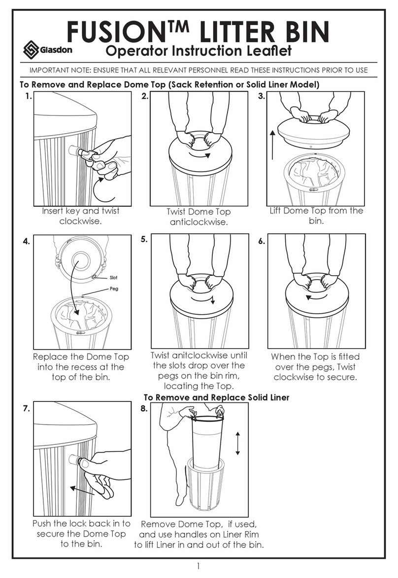
2.2 Slide the gray tubes onto the edges
of the rigid wallet (diagram A) until the
tube reaches the top of the graphic
holder and the hook features rest on
the base of the slot in the tube (ensure
the tubes are assembled so that the
locating holes in each tube are on the
rear face of the graphic holder).
4 off 2 off 2 off
Plastic caps Wall plugs Wall fixing screws
GRAPHIC HOLDER ASSEMBLY INSTRUCTIONS
Fixings Included
Glasdon, Inc.
5200D Anthony Road
Sandston
VA 23150
Sales Inquiries: 1-855-USGLASDON
General Inquiries: 804-726-3777
Fax: 804-726-3778
Web: www.glasdon.com
AND NEXUS®ARE TRADEMARKS OF GLASDON GROUP OR ITS
SUBSIDIARIES IN THE U.K. AND OTHER COUNTRIES
A planned maintenance schedule of regular inspection is recommended,
replacing components as necessary.
Replacement components are available direct from GLASDON, Inc.
GLASDON, Inc. cannot be held responsible for claims arising from
product.
Issue 2 SEPT 2012 C000/0261
©Copyright 2012
Glasdon reserve the right to alter specifications without prior notice. HB391

