GlassCrafters GC1672 User manual

Please use extreme care while unpacking and handling your GlassCrafters’ Mirrored Cabinet. Report any damage
immediately to our GlassCrafters customer service team at 800-233-7362,
Monday thru Friday from 8:00 am to 5:00 pm (EST)
GC2072
GC1672
1
Full-Length Mirrored Cabinet
Installation Instructions
Congratulations on your purchase of Americas nest Mirrored Cabinet by GlassCrafters, Inc.
World class engineering and state of the art design will enable you to enjoy your cabinet for many years to come.
We realize that the marketplace offers many choices and we thank you for selecting
GlassCrafters for your Mirrored Cabinet needs.
The following instruction sheets include the ALL MODELS listed below in both
4” deep and 6” deep Mirrored Cabinets.
Revised 05/2016
GLASSCRAFTERS, INC
193 Veterans Blvd., Carlstadt, NJ 07072
1+(800) 233-7362 (F) 1+(888) 233-7362
To view a video showing helpful tips
on how to --
adjust our Cabinet HInges
or
to install our Mirrored Side Kits,
please go to:
GlassCraftersMirroredCabinets.com
and navigate to the cabinet product
that you are installing.
Simply click on the
installation tab
(located below the
product images)
to view our
installation videos.”
To insure proper installation we recommend installation by a professional installer.
SAVE THESE INSTRUCTIONS
FOR FUTURE REFERNCE

2
1. Cabinet
2. Door, (boxed separately)
3. Plastic Wall Anchors
4. Wall Anchor Screws
5. Bottom Surface Mount Wall Bracket
6. Top Surface Mount Bracket
7. Screw Caps
8. Shelf Clips
9. Hole Plugs
Index
Parts List for All Models ....................................2
Determining the Rough Opening......................3
Recessing the Cabinet .....................................4
Combining two (2) or three (3) Cabinets .........5
Surface Mount Cabinet.....................................6
Full-Length Mirrored Cabinet Installation --
Unpack all parts carefully and protect Glass and Mirror parts during installation.
10. Cabinet Connectors 4” deep*
11. Cabinet Connectors 6” deep*
12. Glass Shelves
13. Cabinet Connector Mounting Screws
14. Hinge Cover Name Plates
15. 130 Degree Limit Clips
16. Soft Close Cushion
17. 3X Magnication Mirror
* Special order
1
17
2
Section
Parts List
Carefully review all parts and read the installation
instruction before you start.
Please refer to page 11 for the exact parts list and
item counts for each model number.
To insure proper installation
in complete compliance with
your warranty,
we recommend installation
by a professional installer.
Surface Mount Side Kit Installation...................7
Glass Shelves...................................................8
Cleaning Recommendation ..............................8 & 12
Door Installation and Adjustment......................9
Limit Clips.........................................................10
Parts Inventory by Model Number....................11
Warranty...........................................................12

Model Number Rough Opening Single Cabinet Overall dimensions
Width Height Width Height
GC1672 14 3/8” 72 1/8” 15” 72 3/4”
GC 2072 18 3/8” 72 1/8” 19” 72 3/4”
3
Tools Required for Installation
GlassCrafters recommends the following tools to
properly and safely install your Mirrored Cabinets.
A. Safety Glasses -- should be worn at all times
B. Tape Measure
C. Level
D. #2 Phillips Head Screw Driver
E. Power Screw Driver
F. Electric Drill
G. 8mm 3/16” Masonry Drill Bit
H. 7/32” Drill Bit
I. Non Ammonia Household Glass Cleaner
J. Soft Paper Towels
Single Cabinet “RO” Rough Opening formula: Overall cabinet width less 5/8” = Rough Open-
ing
Height: overall cabinet height less 5/8” = R.O. Height.
Cabinets are supplied with left or right hinges. Be sure to install with the correct hinged side
as per the room plans.
Important: Make sure you allow for a minimum of
4” toe kick clearance above the nished oor.
Rough Opening:
Note: Cabinet installs over nished wall with sheetrock
and/or tile nishes completed. 3/4” Flange on all sides of
the cabinet will cover the remaining space in the R.O.
Determining the Rough Opening “RO” Dimension
Framing in new construction should follow these dimension. Standard 2x4 studs and 1/2” sheetrock are shown in the il-
lustrations. For 6” deep models 2x6 studs are required or a semi-recessed application is necessary.
Recommended Clearance
4” for Toe Kick
Above Finished Floor

4
Installing a
Recessed & Semi-Recessed
Mirrored Cabinet
A. Determine the rough opening for the cabinet. Refer to
“R.O.” formula chart on page 3. Opening must be plumb
and level.
B. Cabinet comes hinged on left or righ side. Be sure to
determine the proper hinge location for the unit before in-
stalling.
C. Insert cabinet in R.O. and center, Cabinet Flange cov-
ers any space in the R.O. around the cabinet and should
cover the nished surfaces--Sheetrock and/or tile.
Install the cabinet with four (4) #10 x 1 1/2” wood screws
(supplied). Use the pre-punched holes above and below
the hinge plates (as shown). Do not overtighten. Cover
screws with screw caps (part #434).
2x4
Framing
Shown
PLUMB
LEVEL
B
AC
Hinge Plate shown for right hinged door. Handed door
is determined at the time of order. Be sure to install with
left or right hinged unit on the correct side.
Drawings not shown to scale
for Full-Length
Mirrored Cabinets

Parts required to join Two (2) Cabinets:
Cabinet Connector Screws Qty Screw Qty
depth Part# Qty Caps
4” deep #426 3
10-32 x 1 1/2”
12 #434 12
6” deep #429 3
10-32 x 1 1/2”
12 #434 12
Left Top
Right Top
Left Top
Center Top
Right Top
Left Top Right Top
Section 1 Cabinet Flanges
meet here
5
Combining Two (2) or Three (3)
Cabinet Units before Installation.
Any of the cabinets that are the same height may be
joined to form one unit. Follow these instructions to cre-
ate the nal size unit before attempting installation.
• Be sure to determine the hinge side door swing
location for each unit.
• Mark the top of each unit-- Left, Right or Center with
the Hinge plates in the proper position.
When the unit is fully assembled refer to “R.O.” formula
chart on page 3 to determine the R.O. required for the
unit as assembled.
Assembling multiple cabinet units:
1. Place the units on a 2x4 or 2x6 of sufficient horizontal
length to support all the units to be joined. Place 2” edge
of the wood at on the oor with the cabinet facing up
with the bottom ush to the inside edge of the 2x4.
2. Install the Cabinet Connector (part #426 or 429) on the
outside of the left hand cabinet. Use the pre-punched
holes immediately above and below the hinge plate loca-
tions. Use screws 10-32 x 1/2” as supplied. (See Section
#1)
3. Move the second cabinet into position so that the face
ange of both units are aligned. Fix the cabinets together
using screws 10-32 x 1/2” as supplied. (See Section #1).
4. If there is a third unit follow the steps above.
Shown here -- Left, Right and Right
hinge side door swings
Shown here -- Left and Right
hinge side door swings
Parts required to join Three (3) Cabinets:
Cabinet Connector Screws Qty Screw Qty
depth Part# Qty Caps
4” deep #426 6
10-32 x 1 1/2”
20 #434 20
6” deep #429 6
10-32 x 1 1/2”
20 #434 20
Drawings not shown to scale
for Full-Length
Mirrored Cabinets

6
4” Clearance above
finished floor
4” Clearance for Toe Kick
Installing a Surface Mount Mirrored Cabinet
A. Determine the desired height and use a level to mark a horizontal line. Be
sure to allow a minimum clearance of 1” above any base molding or a mini-
mum of 4” for Toe Kick. Remember the base of the cabinet box is 3/4” smaller
than the face and the door.

7
Side Mirror Kit Installation
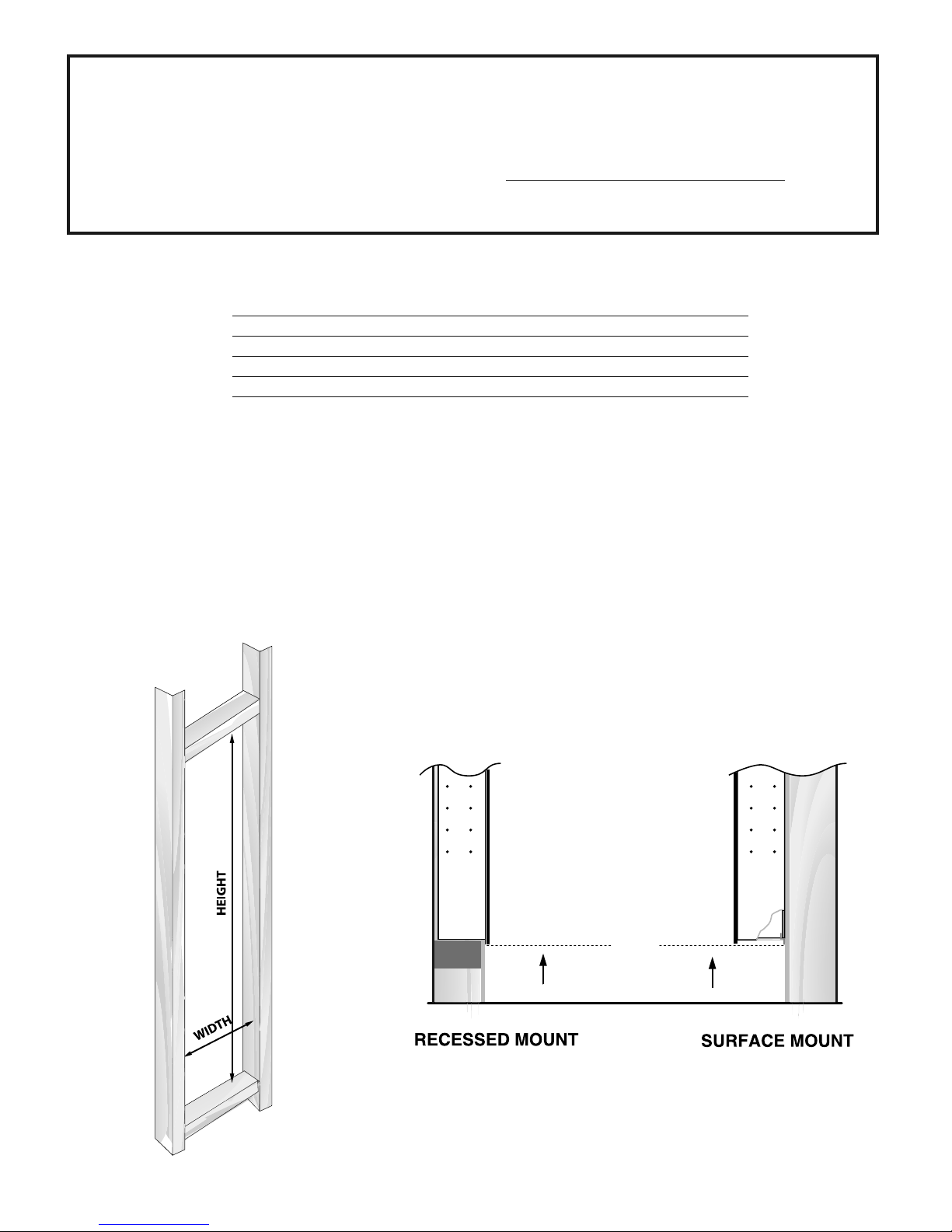
For surface mounted 4” & 6” Mirrored
Cabinet and semi-recessed 6” Mirrored
Cabinets.
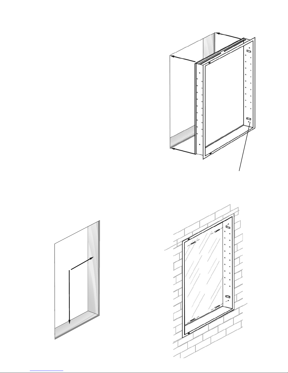
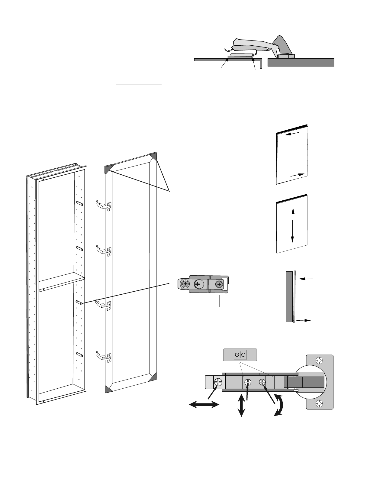
1) Attach the side mirror kit brackets thru
the pre-punched holes in your cabinet.
2) Try to use the rst row from the top and
bottom of your cabinet. Using the twelve 10-
32 x 1/2” screws fasten the
brackets and nish with screw caps.
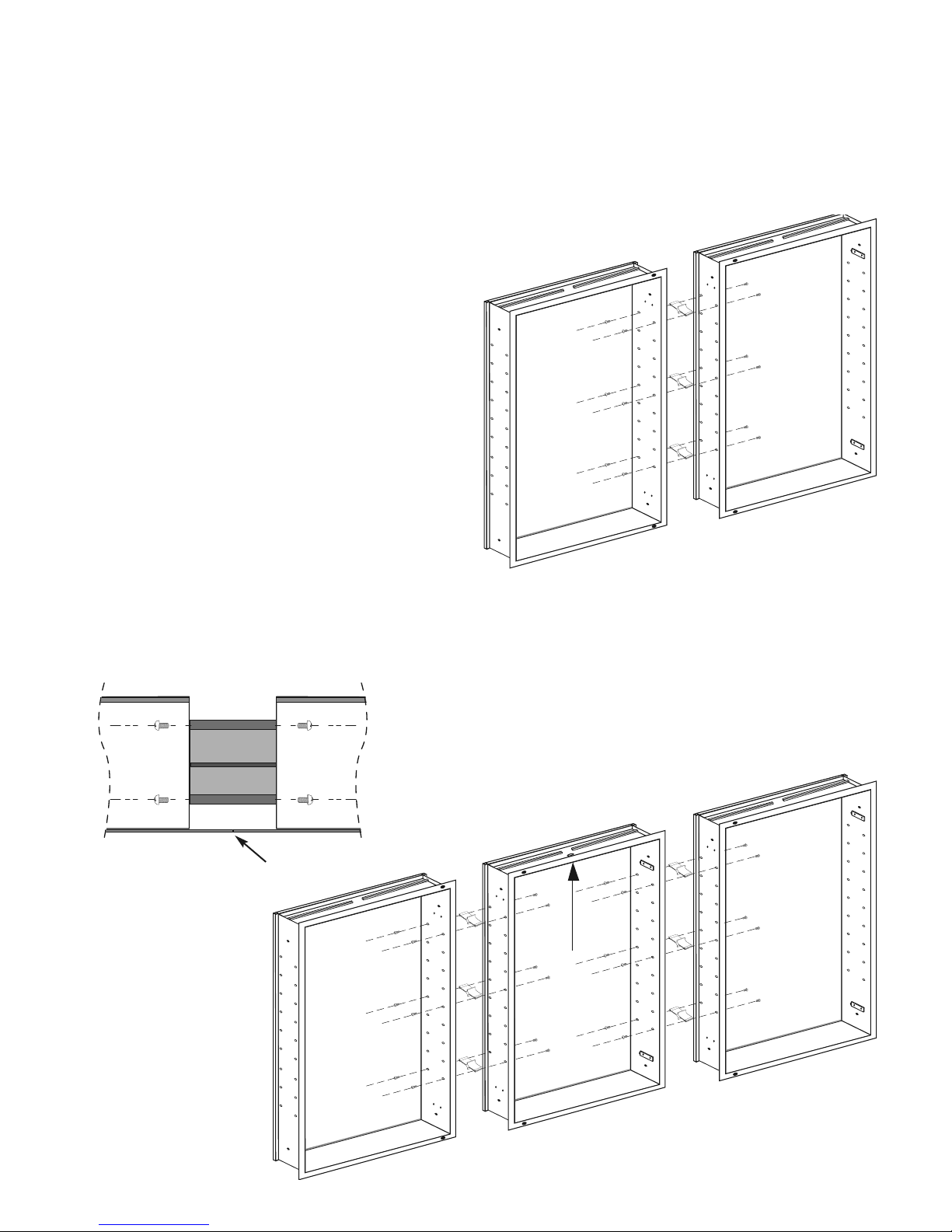
3) Attach the 2” x 2” foam pads to the out-
side cabinet wall above, below and in be-
tween the position of the brackets (to affix
mirror to bracket).
4) Clean the backside of the side mirror kit
panel with the Alcohol pads. Check align-
ment before you attach the mirror to be sure
it will align even with the top of the cabinet.
5) Peel off paper covering of the adhesive
tape on the side kit brackets pads. (This
holds the mirror in place). Carefully align
the mirror to the cabinet evenly on all four
sides. Press rmly into place and attach to
the side kit mirror to the cabinet body.
(Note: Once installed, do not try to remove the
mirror as it will break.)
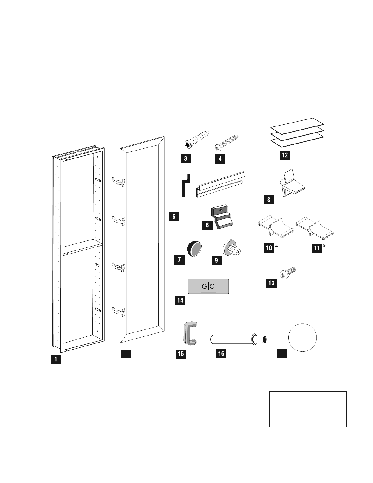
Side Mirror Kit parts list:
• Mirror side panels to match the model
height ordered
• 6 Side kit brackets with adhesive tape
(to hold the side mirror in place)
• 12 2”x 2” Black Foam Pads with peel off
adhesive backing (to affix to cabinet)
• 12 Screws, 10-32 x 1/2”
• 12 Screw Caps ( part # 434-00)
• 2 Alcohol Pads
Align mirrorto level
with TopEdge
Side MirrorKit Bracket
2”x 2”Black
Foam Pads
with peel off
ahesive side
affix pads
to the
cabinet
Peel off paper covering adhesive
Side MirrorKit Bracket
Peel off paper covering adhesive
Side Mirror
Side Mirror
Install Side Mirror:
• Install foam pads
on the outside wall
above, below and
in between
the brackets
• Clean back side of
mirror with
alcohol pads
• Peel-off paper
covering the
adhesive tape
on the brackets-
(this holds the
mirror in place)
• Align mirror
top and bottom
• Press firmly in place
(Do not try to remove
mirror as it will break)
To view a video showing helpful tips on how to install side mirror
kits, please go to GlassCraftersMirroredCabinets.com and
navigate to the cabinet product that you are installing. Simply click
on the installation tab (located below the product images) to view
our installation videos.
Side Mirror Bracket
Side Mirror
10-32 1/2” Screws
2” x2” FoamPads

8
Glass Shelves Installation
After the Mirrored Cabinet box has been properly in-
stalled, determine the appropriate height and location for
the glass shelves.
Note: make sure the back wall mirror has been
completely cleaned after installation. If cleaning the back
wall mirror is necessary, use a household non-ammonia
glass cleaner.
Cleaning Recommendations:
Never use abrasive cleaners or cleaners containing
ammonia. This may cause chemical damage to the
mirror and void the warranty.
72” Height Series = 8 Shelves + 32 Shelf Clips
For cleaning the mirror, we recommend using
“ammonia free” Sprayway brand glass cleaner,
which is available at a variety of retail outlets.
www.spraywayinc.com/content/glass-cleaner
Each glass shelf will require four (4) shelf
clips. Use care when handling the non-tem-
pered glass shelves. On a level plane insert
the shelf clips into the pre-punched holes. The
clips are designed for a tight tension t to hold
the shelf. Place each glass shelf on the top of
the left clip rst, then slowly lower onto the right clip with
a snap t.
After glass shelves are installed insert hole plugs in all
open holes to complete installation.
Hole Plugs
Drawing not shown to scale for Full-Length
Mirrored Cabinet

9
Hinge CoverName Plate
#1 Screw-
Adjust Left to Right
#3Screw-
Adjust
Front to Back #2 Screw-
Adjust
Topto Bottom
1) Insert into
Hinge Toe
first
Hinge Plate
2) Lift and snap
into place Doorwith Hinge
After door adjustments are completed place cover caps on hinges.
Blum Hinge Adjustment
#3
Screws adjust
for Flush Fit
to cabinet face
#2
Screws adjust
for Fit to
Top and Bottom
to cabinet face
#1
Screws adjust
for Fit alignmen
left and right
to cabinet face
Hinge Plate*
Factory Installed.
*If the door binds and does
not fully close, adjust the
Hinge Plate on the cabinet up
and down, to relieve the ten-
sion
Door Installation
The doors are packed individually for protection of the
mirror surfaces. Carefully remove the door from the
carton.* Hold the door in the upright position snap
open the factory installed hinges. Place the hinge onto
the factory-installed mounting plate in the cabinet --
Toe rst -- and snap into position. Be careful not to
chip the door mirror.
Cabinets are supplied with left or right hinges. Be sure to install
with the correct hinged side as per the room plans.
*Do not remove corner protectors until the door is
installed. Removing the Door Protectors prior to
installation will damage the mirror.
Hinge Toe Plate
Corner Protectors
To view a video showing helpful tips on how to adjust our cabinet
hinges, please go to GlassCraftersMirroredCabinets.com and
navigate to the cabinet product that you are installing.
Simply click on the installation tab (located below the
product images) to view our installation videos.

10
Limit Clips
Limit Clips are provided should you need to reduce the
opening swing of the cabinet door from 170 degrees to
130 degrees (see top view) This will eliminate the possi-
bility of the door hitting a wall sconce or other decorative
items.
Rececess Cabinet DoorSwing Diagrams
Finishedsurface
Finishedsurface
Cabinet
Cabinet
170º swing
130º swing

11
Model: GC1672-4"
Model: GC 1672-6”
Qty. Part Number
Cabinet 4" Cabinet 1 GC1672-4-Cab
Cabinet 6" Cabinet 1 GC1672-6-Cab
Door - Boxed Separately 1 GC1672-D
Plastic Wall Anchor 5 # 10 PWA
Wall Anchor Screws 5 # 10 x 1 1/2 Phillips
Bottom Surface Wall Mount Bracket 1 414-03
Top Surface Mount Brackets 2 425-00
Screw Caps 12 434-00
Shelf Clips 32 439-01
Hole Plugs 80 433-00
*Cabinet Connectors 4" Cabinet 3 426-00
*Cabinet Connectors 6" Cabinet 3 429-00
*Cabinet Connector Mounting Screws 12 18-855 10/32” x 1/2"
Glass Shelves 4" Cabinet 8 417-01-A 3 7/16” x 13 1/4" x 5/16"
Glass Shelves 6" Cabinet 8 417-06-A 5 7/16” X 13 1/4" X 5/16"
Hinge Cover Name Plates 4 904-00
130 Degree Limit Clip 4 901-00
Soft Close Cushion 3 900-00
3X Magnfication Mirror 1 950-01
Model: GC 2072-4"
Model: GC2072-6"
Qty. Part Number
Cabinet 4" Cabinet 1 GC2072-4-Cab
Cabinet 6" Cabinet 1 GC2072-6-Cab
Door - Boxed Separately 1 GC2072-D
Plastic Wall Anchor 5 # 10 PWA
Wall Anchor Screws 5 # 10 x 1 1/2 Phillips
Bottom Surface Wall Mount Bracket 1 414-03
Top Surface Mount Brackets 2 425-00
Screw Caps 12 434-00
Shelf Clips 32 439-01
Hole Plugs 80 433-00
*Cabinet Connectors 4" Cabinet 3 426-00
*Cabinet Connectors 6" Cabinet 3 429-00
*Cabinet Connector Mounting Screws 12 18-855 10/32” x 1/2"
Glass Shelves 4" Cabinet 8 417-02-A 3 7/16” x 17 1/4" x 5/16"
Glass Shelves 6" Cabinet 8 417-07-A 5 7/16” X 17 1/4" X 5/16"
Hinge Cover Name Plates 4 904-00
130 Degree Limit Clips 4 901-00
Soft Close Cushion 3 900-00
3X Magnfication Mirror 1 950-01
*Cabinet Connectors -- Special Order
This installation manual serves
the complete line of
GlassCrafters Full-Length
Mirrored Cabinets including all
4” deep and 6” deep models.
The general parts list pictured
on page 2 shows the single
images of a part. To completely
inventory the material delivered
for your particular model
please check the quantities
indicated in the part list here.
Master Parts List for
Full-Length Mirrored Cabinets

12
WARRANTY
GlassCrafters, Inc. offers a Limited 3 Year Warranty on all mirrored cabinet products.
GlassCrafters’ warranty provides the original purchaser a guarantee that it will replace or
at its own discretion repair products shown to have substantial defects in workmanship
or materials. These claims must be led with your dealer or professional installer and for-
warded in writing to GlassCrafters within three years of the delivery date to the end user
of the product. GlassCrafters shall not be responsible for any installation or removal
costs. This warranty does not apply to the following, chemical or natural corrosion of the
mirror. The use of abrasive cleaners or cleaners containing ammonia will cause chemi-
cal damage to the mirror, voiding this warranty.
The GlassCrafters warranty does not cover product that is damaged in shipping, acci-
dents in handling during installation or if the reported defects are a result of faulty instal-
lation, abuse, misuse, abnormal wear, poor maintenance, accident or repairs by service
personnel other than the original professional installer as authorized by GlassCrafters.
After the three year period GlassCrafters shall not have any further obligation, expressed
or implied including merchantability under the Limited Warranty.
Blum hinges and soft closing cushions have a separate lifetime warranty from
Blum, Inc. This warranty is against defects in materials and workmanship as long as
the original consumer owns the product. This is a warranty of replacement. After veri-
cation of defect, Blum, Inc. will send replacement hardware without charge.
GlassCrafters shall not have any liability for any consequential damages stemming
from or in connection with the use per performance of this product. Prevailing state
law on the limits of the implied warranty will apply.
The liability of GlassCrafters under any implied or expressed warranty, including mer-
chantability, is expressly limited to the terms of this warranty. Any claim under this
warranty must be made directly to the dealer of record.
Permission to return any merchandise under this warranty must be authorized in writ-
ing by GlassCrafters and must include prepaid shipping by the purchaser.
Revised 05/2016
GLASSCRAFTERS, INC
193 Veterans Blvd., Carlstadt, NJ 07072
1+(800) 233-7362 (F) 1+(888) 233-7362
Cleaning Recommendations:
Never use abrasive cleaners or cleaners
containing ammonia. This may cause
chemical damage to the mirror and void
the warranty.
For cleaning the mirror, we recommend using
ammonia free Sprayway brand glass cleaner,
which is available at a variety of retail outlets.
www.spraywayinc.com/content/glass-cleaner
To view a video showing helpful tips on how to -- adjust our Cabinet HInges or to install our Mirrored Side Kits, please go to:
GlassCraftersMirroredCabinets.com and navigate to the cabinet product that you are installing. Simply click on the installation tab
(located below the product images) to view our installation videos.
This manual suits for next models
1
Table of contents
Other GlassCrafters Indoor Furnishing manuals
Popular Indoor Furnishing manuals by other brands

Pebble Grey
Pebble Grey Hadley 500.20.12 Assembly instructions

True Innovations
True Innovations 44172 operating instructions

Incy Interiors
Incy Interiors Jude Bookcase manual

2K Furniture Designs
2K Furniture Designs D6691-1 Assembly instructions

ROVO
ROVO 2070 S1 quick start guide

sedia systems
sedia systems Mercury Assembly instructions