Glem GHD670IX User manual


1
GHD67IX- GHD77IX - GHB970IX - GHS91BK - GHR970IX
GHQ970IX - GHS970IX - GHS91IX - GHD97IX
GHI91BK - GHQ91IX - GHI91IX
GHW31IX - GHW41IX - GHW91IX

2
CONTENTS
1.Safetyinformation 3
2. Setting the speed 6
3. Maintenance 7
4. Main features 7
5.Beforeinstalling 8
6. Installation instructions 8
7. Troubleshooting 18
8. Technical details 20
For future reference please record the following information, which can be found on the nameplate (model and serial no.)
and on the sales invoice (date of purchase). The nameplate is located under the motor cover (glass models) or inside the
cooker hood, on the left (other models).
Model no. ……………………………….
Serial no. ……………………………….
Date of purchase ……………………………….

1. SAFETY INFORMATION
Read this manual carefully before installing or
using the cooker hood.
The hood should be installed by a qualified or
expert person.
• Install the hood following the instructions
contained in this manual and all relevant
safety regulations.
• If the cooker hood is installed above a gas-
fired appliance, the ventilation system must
comply with gas safety standards BS.6172,
BS.5440 and BS.6891 (Natural Gas) and
BS.5482 (LP Gas) 1994, with gas safety
regulations (installation and use) and with
building regulations.
• It is dangerous to change product specifica-
tions or modify the product in any way. Do no
tamper with the hood or try to alter it in the
attempt to customize it further.
• During installation, leave the following dis-
tance between the cooktop and the bottom of
the cooker hood:
Electric cookers: 700 mm
Gas cookers: 700 mm
Coal/oil cookers: 800 mm
Do not install the cooker hood at less than
700 mm from the cooktop.
3

• Do not install the cooker hood over cookers
equipped with hotplates.
• If the hood is installed between adjoining
wall cabinets, the cabinets should not over-
hang the cooktop.
• The cooker hood has sharp edges: handle
the hood with care, especially during installa-
tion and cleaning. DO NOT CLEAN BEHIND
THE GREASE FILTERS!
• If there is a fuel-burning appliance (e.g., a
central heating boiler) in room where the
cooker hood is installed, make sure the
appliance’s flue is perfectly sealed.
• If there are other kinds of flues or appli-
ances, make sure there is adequate ventila-
tion inside the room.
• If you are planning to use the cooker hood’s
extraction function, make sure the exhaust
duct is fireproof and that there are no bends
sharper than 90°, as that would reduce the
hood’s efficiency.
• Make sure the exhaust duct has the same
diameter of the outlet hole along its entire
length.
• Keep young children from using, tampering
or playing with the cooker hood. Older chil-
dren and infirm persons should be supervised
when using the cooker hood.
• Your cooker hood is for home use only.
4

• Dispose of the packing material safely, as it
can be hazardous for children.
• Used oil represents a serious fire hazard.
• Always put lids on pots and pans when
cooking on a gas cooker.
• The Manufacturer declines all responsibility
for damages to the hood or its catching fire
due to failure to observe the safety instruc-
tions in this manual.
• When working in extraction mode, the
cooker hood is removing air from the room.
Make sure the room is adequately supplied
with fresh air. Please note that the hood is de-
signed to remove odours from the room, but
not steam.
• Warning! Before servicing the cooker hood
in any way, including replacing a lamp, dis-
connect the hood from the power supply.
• Do not connect the hood exhaust duct to an
existing ducting that is used for any other pur-
pose.
• Do not install the hood over a cooker with a
raised grill.
• Do not leave frying pans unattended, as
overheated grease and oil are liable to catch
fire.
• Do not leave open flames under the cooker
hood.
5

• Dot not attempt to use the cooker hood if it
is damaged in any way. Do not attempt to use
the cooker hood without the grease filters
installed or if the filters are excessively
greasy!
• Do not flambé under the cooker hood.
• Do not allow the hood to be used by chil-
dren.
• The cooker hood is for home use only: it has
not been designed nor is it intended to be
used for barbecues, fast-food restaurants
or other commercial purposes.
• Always have a qualified person install the
cooker hood.
• Periodically clean the cooker hood and the
filter grid to ensure its proper functioning at all
times.
• Disconnect the cooker hood from the power
supply before cleaning.
• Follow the manual’s instructions when
cleaning the cooker hood.
• Contact the service centre immediately in
case of damages or malfunctions in the
cooker hood.
2. SETTING THE SPEED
Electronic button
1. Turn on the air intake. You will hear 5 beeps. The beeps are just a signal to inform you that the device is properly
connected to the power supply.
2. Press the “Low” button (low speed). Indicator light 1 turns on, the devices beeps once and the motor starts running at
low speed. Press the button again to stop the motor.
3. Press the “Mid” button (half speed). Indicator light 2 turns on, the devices beeps once and the motor starts running at
half speed. Press the button again to stop the motor.
6

7
4. Press the “High” button (full speed). Indicator light 3 turns on, the devices beeps once and the motor starts running at
full speed. Press the button again to stop the motor.
5. Press the “Light” button. Indicator light 4 turns on and the two lights in the cooker hood turn on. Press the button again
to turn off the lights. Every time you press the button the device will beep.
3. MAINTENANCE
Removing the grease from the filter
The filter mesh consists in a very thick stainless steel grid. Do not use corrosive cleaning agents. Keep the filter clean to
make sure that the hood works properly at all times. Follow the instructions below carefully.
Procedure 1: Put the filter mesh in clean water at a temperature of 40 – 50ºC. Add a cleaning agent and let it work for 2 –
3 minutes. Wearing gloves, clean the filter mesh using a soft brush. Do not press: the mesh is fragile and can be easily
damaged.
Procedure 2: Wash the filter mesh in a dishwasher if allowed by the manual. Set the temperature to approx. 60ºC.
Cleaning the cooker hood
1. To protect the body of the cooker hood from corrosion, clean the hood every two months with hot water and a non-
corrosive cleaning agent.
2. Do not use abrasive cleaning agents as they might damage the body.
3. Do not let water come into contact with the motor to prevent damaging it.
4. Turn off the main switch before cleaning the hood.
5. Do not expose the carbon filter to high temperatures.
6. Do not open the fastener around the carbon filter. Replace the cable or plug if faulty or damaged.
Note
The Manufacturer declines all responsibility for damages or injuries caused by failure to observe the installation
instructions below.
4. MAIN FEATURES
1. The cooker hood is made of top quality materials. It has a rounded, aerodynamic shape.
2. The hood is equipped with an efficient, low-noise electric motor, a high-power, low-noise centrifugal suction fan and an
easy-to-clean grease filter.

8
3. An insulated control panel powered by low-voltage electricity (12 V DC) guarantees the safety of the lighting system.
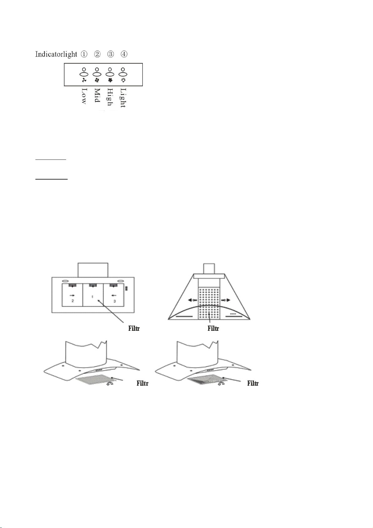
4. The cooker hood is very efficient in capturing dirt particles in the air thanks to the special construction of the air duct
and the shape of the oil catcher.
5. The cooker hood is powered by household electricity at 220/240 V, 50 Hz.
5. BEFORE INSTALLING
1. Make sure the room is clean before installing the cooker hood. Avoid the suction of wood chips and dust.
2. The cooker hood must not share the same ventilation pipe with other devices, e.g., gas ovens, heating furnaces or
hot-air ovens.
3. The angle of the bend of the ventilation pipe should not be less that 120º; the pipe should run horizontally or,
alternatively, rise vertically from its start and then run towards an external wall.
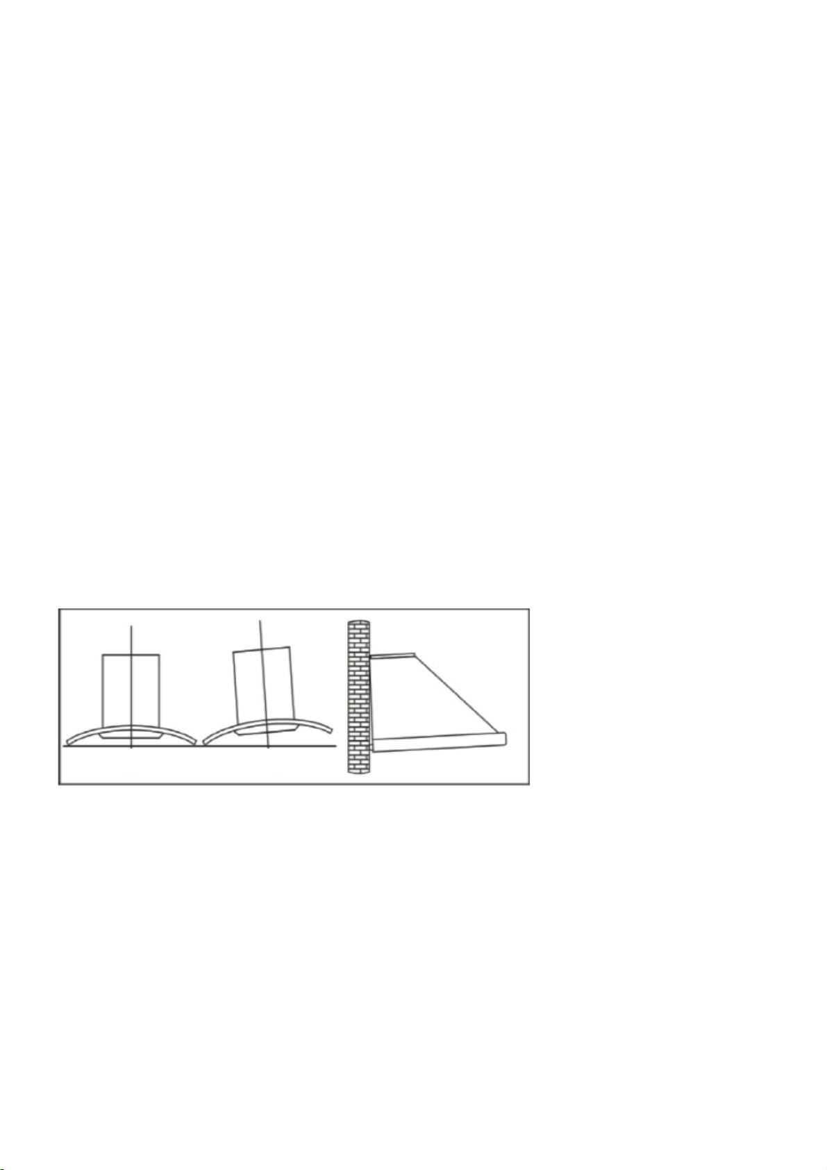
4. After installing the cooker hood, make sure that it is horizontal. This will prevent the grease from gathering at one end.
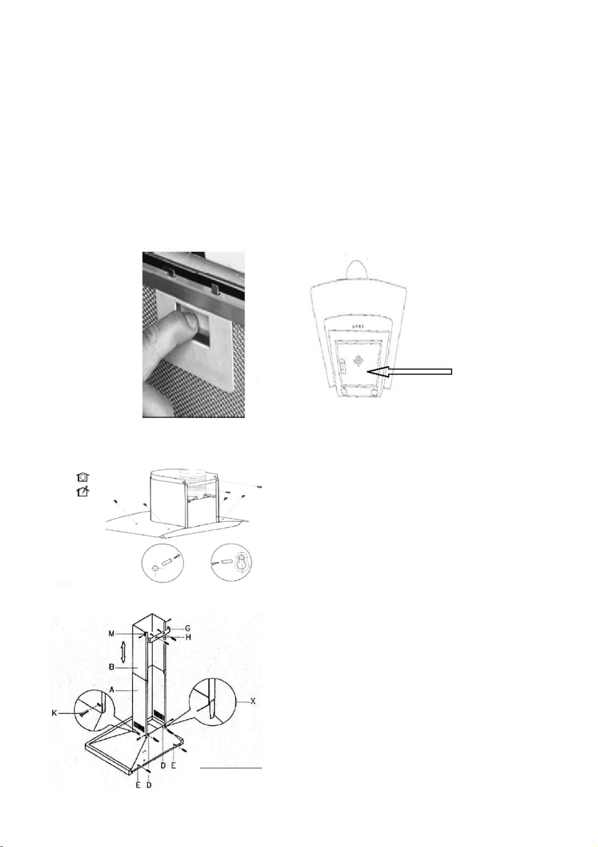
6. INSTALLATION INSTRUCTIONS
Before installing the cooker hood you must decide whether you want to use it as an extractor hood or as a filter hood (for
recirculation).
What’s the difference between extraction and recirculation?
In order to get the best performance from your cooker, air is removed from the room through an exhaust duct that leads
outdoors. Unfortunately, if you live in a flat or if the hood is too far from an external wall, that may not be possible. In this
case the only alternative is to recirculate the air.
In recirculation mode stale air is sucked in through the grease filter and passed through an active-carbon filter for
purification, after which the purified air is returned to the room via an opening in the hood.
What is a carbon filter and do I need one?
All cooker hoods come with a grease filter, but if the hood is used for recirculation (filter hood) an active-carbon filter is
required in addition to the grease filter.
Right Wrong Wrong

9
Models: GHB970IX - GHS970IX - GHS910IX - GHS910BK - GHQ970IX - GHR970IX - GHD670IX -
GHD770IX - GHD970IX
These hoods are designed to be wall-mounted only. DO NOT INSTALL at less than 700 mm (70 cm) from the cooktop.
1. Remove the metal grease filter (see Fig. 1).
2. Set the hood against the wall and mark the position of the auxiliary holes (you will need to bore the holes with a drill –
see the figure below). The auxiliary holes are showing in Fig. 2 (next page), marked by the letter “D”, together with the
anchoring holes, marked “E” (Fig. 2, next page). If the cooker hood is provided with an eyelet for hanging, use the eyelet
as a guide to mark the holes to be drilled.
3. Drill the holes in the wall in the places you marked earlier, using a 6 mm drill bit (see Fig. 3).
4. Insert the dowel pins in the holes and screw the auxiliary bolts in half-way (see Fig. 4).
5. Hang the cooker hood on the bolts (see Fig. 5) and fasten it to the wall. Firmly tighten the auxiliary bolts and the
anchoring bolts (next page, top).
6. (FOR EXTRACTION FUNCTION ONLY) Insert the connection coupling at the top of the cooker hood (see Fig. 6).
Connect the exhaust pipe (see below). The exhaust pipe must comply with the specifications given in the section on air
extraction/purification (recirculation).
Fig. 1 –Grease filter
Fig. 2 –Rear view of the cooker hood

10
Fig. 3
Fig. 4
Fig. 5

11
Installing the ventilation pipe
Once the cooker hood is installed, install the ventilation pipe.
1. Get ready the two covers, “A” and “B”.
2. Place the bottom part of cover “A” on the top of the cooker hood, making sure to correctly position the fastening points
on the cover, marked “X” (see Fig. 7), against the back of the cooker hood.
3. Install cover “A” on the cooker hood using the two bolts, “K”, supplied in the accessories pouch (Fig. 7).
4. Lift the moving cover, “B”, up to the ceiling. Make sure the hood is in a perpendicular position.
5. Mark the side position of the moving cover, “B”, and let it slide down (see Fig. 8).
6. Take the fastening support, “G”, (Fig. 7, previous page), centre it (using the marks) while it touches the ceiling and
mark the position of the anchoring holes, “H”.
7. Drill the holes in the wall in the places marked, using a 6 mm drill bit (see Fig. 9).
8. Insert the dowel pins into the holes, put the support, “G”, in position (Fig. 7, previous page) and fasten it using the bolts
supplied.
9. Lift cover “B” up to the ceiling and fasten it to the support, “G”, by inserting the bolts into the holes, “M” (Fig. 7,
previous page).
Fig. 7
Fig. 6

7
Installing the glass (Fig. 11)
1. Remove the metal grease filters from the cooker hood.
2. Loosen both anchoring bolts “F”.
3. Place the glass, “Q”, on the upper surface of the cooker hood and push it towards the wall.
4. Tighten bolts “F” again and fasten them to the unit.
5. Make sure the angle section is correctly in place and firmly tightened.
6. Reinstall the ventilation pipe with the connection coupling, “N”.
7. WARNING! DO NOT TIGHTEN THE BOLTS EXCESSIVELY TO AVOID DAMAGING/DEFORMING THE UNIT.
Extraction function (extractor hood)
Make sure the connection coupling (“N”) is fastened to the upper part of the cooker hood by two bolts (Fig. 1, right).
Using a Ø125 mm pipe, connect the coupling (“N”) on the upper part of the cooker unit (see Fig. 12) to the pipe that will
be used to extract kitchen vapours, having a section of at least 150 cm2.
Note
If you do not a pipe that can remove vapour, and the cooker hood is to be installed on an external wall, drill a hole in the
wall large enough to install a fan and a rainproof ventilation grille (having a section at least 150 cm2). Connect it to the
outlet coupling by means of a pipe.
Lastly, for the extraction function, connect the 125 mm pipe to the point marked “N” (see Fig. 1, above). (The pipe is not
supplied.)
Recirculation function (filter hood)
If an external pipe for exhaust air cannot be installed, the cooker hood can be set up to work as an air cleaner (filter
hood).
In this case, the air is recirculate
through the air vent. If you use
the unit as an air cleaner (filter
hood), you will have to install
two carbon filters to absorb the
kitchen vapours.
Fig. 8
Fig. 9
Fig. 10
Fig. 8
Fig. 9
Fig. 10

13
Instructions
for installing
Models: GHI910IX - GHQ910IX - GHI910BK
1. The ceiling must be capable of supporting a weight of at least 40 kg and have a minimum thickness of 30 mm (see
Fig. 2). Drill 1*170 mm round hole in the ceiling.
Fig.11
Fig. 12

14
2. Depending on the type of panel, drill 12 holes in the ceiling (see Fig. 2). Twelve ST6*40 mm large flat screws will be
used to fasten the panel to the ceiling, and 8 M4*10 screws and an M4 nut and washer will be used to attach the angle
iron to the panel (see Fig. 1). After calculating the length of the angle iron, use 16 M4*10 large flat screws and one M4
nut and washer to attach the angle iron and an additional angle iron (the overlap between the angle irons should not
exceed 100 mm).
3. Pass one end of the extensible pipe through the 170 mm hole (see Fig. 3).
4. Use 4 ST4*8 large flat screws to connect the internal chimney to the panel that will be used to suspend the hood. Lift
up the external chimney and hang it to the two hooks before the next installation steps (see Fig. 4).
5. Install the outlet using 4 ST4*8 large flat screws (see Fig. 5).
6. Adjust the 4 glass screws to make sure the glass and the unit’s body are properly attached and fastened (see Fig. 6).
7. Holding up the unit, connect the body to the angle iron using 16 M4*10 large flat screws (see Fig. 7).
Place the extensible pipe on the outlet. Once everything is as required, pull the hood and the chimney down, thereby
completing the installation (see Fig. 9).
Fig. 1 Fig. 2 Fig. 3
Fig. 4

15
Model GHW310IX
Installing the glass
1. Take the chimney out of its packing and place it upside down on a panel. Loosen the filter knobs by turning them
anticlockwise, and pull the filter out as shown in Fig. 1.
2. Using a screwdriver, remove the screws on the small cylinder and the junction box (see Fig. 2).
3. Open the junction box and disconnect all the hood light wires, then take the parts out of the small cylinder (see Fig. 3).
4. Lay the glass over the larger cylinder’s connection panel so that the two holes on the glass correspond with the two holes
on the connection panel (see Fig. 4)
5. Cover it again. Make the four slots of small cylinder versus the four prongs of the link coil, then put it on the glass.
Tighten the four loosened screws. Reconnect the light wires, put them back in the junction box and lock the box with the
two screws. Lastly, cover the filter and lock it in position (see Fig. 5, Fig. 6 and Fig. 7).
Fig.1 Fig.2 Fig.1
Fi
g
5 Fig 6
Fig 7Fig 8
Fig 9

16
Fig.5 Fig.6
Fig. 4
Fig. 7
Installation with glass
1. For best performance, the cooker hoods must be installed at a distance of 65-75 cm from the cooktop (see Fig. 8).
2. In case of wall installation, drill three Ø8 mm holes every 100 mm in a suitable place in line with the hook on the hood.
Drill a hole on the ceiling having the same size of the decorative pipe.
3. Insert the expansion bolts into the holes. Fasten the hook to the wall (see Fig. 9).
4. Add the soot pipe to a one-way valve and extend it to the desired height (see Fig. 10).
5. Hang the hood on the hook (see Fig. 11 and Fig. 12).
Fig. 8 Fig. 9 Fig. 10
Fig. 11
Fig.12

17
Installation without glass
1. For best performance, the cooker hoods must be installed at a distance of 65-75 cm from the cooktop (see Fig. 8).
2. In case of wall installation, drill three Ø8 mm holes every 100 mm in a suitable place in line with the hook on the hood.
Drill a hole on the ceiling having the same size of the decorative pipe.
3. Insert the expansion bolts into the holes. Fasten the hook to the wall (see Fig. 13).
4. Add the soot pipe to the one-way valve and extend it to the desired height (see Fig. 14).
5. Hang the hood on the hook (see Fig. 15 and Fig. 16).
Model GHW410IX
Installation
1. For best performance, the cooker hoods must be installed at a distance of 65-75 cm from the cooktop (see Fig. 1).
2. In case of wall installation, drill three Ø8 mm holes every 100 mm in a suitable place in line with the hook on the hood.
3. Insert the expansion bolts into the holes. Fasten the hook to the wall (see Fig. 2).
4. Add the soot pipe to the one-way valve and extend it to the desired height (see Fig. 3).
5. Hang the hood on the hook (see Fig. 4).
Fig. 2 Fig. 3

18
Fig. 4
Model GHW91IX
INSTALLATION
1. The cooker hoods should be placed at a distance of 65-75cm from the cooking surface for best effect. See pic1.
2. To install onto the wall every 100mm drill 3 holes of Ø8mm on a suitable place in line with the hook on the hood.
3. Insert expended screws into the holes.
4. Fix the hook on the wall, put Drilling template on the hook. See pic2.
5. Add the soot tube to the one way valve, and put it outdoor. See pic3.
6. Calculate the final height of the U-shaped section, pull out the inside U-shaped section to a suitable height. (See pic
4). Finally, drill 2 holes of Ø8mm on a suitable place in line with the 2nd plate. Repeat 3.3. Put the inside U-shaped on
the 2nd plate and tighten the two screws (see pic4a).
7. TROUBLESHOOTING
Problem Cause Solution
Fan locked Release fan lock
Faulty capacitor Replace capacitor
Faulty motor bearings Replace motor
Light turns on but motor not running
Internal motor winding burned, or bad
odours coming from motor
Replace motor
Check the above, and then the following:
Damaged lamp Replace lamp
Light does not turn on and motor not
running
Power cord disconnected Connect power cord (see wiring

19
diagram)
One-way valve and inlet to ventilation
system improperly closed
Remove one-way valve and seal with
filler
Grease leak
Leak from connection between U-
shaped part and cover
Remove U-shaped part and seal with
soap or paint
Faulty fan causes vibration Replace fan
Motor improperly installed Fasten motor
Hood vibrates
Cooker hood body improperly
installed
Fasten cooker hood body
Distance between hood body and
cooktop too large
Adjust distanceInsufficient suction
Excessive airflow from open doors or
windows
Choose another point of installation
and set the appliance closer
Hood is tilted Suspension bolts loose Tighten suspension bolts and place
hood in horizontal position
This manual suits for next models
14
Table of contents
Languages:
Other Glem Ventilation Hood manuals

Glem
Glem GQA90SC Operating instructions

Glem
Glem COOKER HOOD PN-36 User manual

Glem
Glem GHF527SI User manual

Glem
Glem GHBS97IX User manual

Glem
Glem CKS61MXI User manual

Glem
Glem GHI9100BK User manual

Glem
Glem CK90TBLED Specification sheet

Glem
Glem GHB972IX User manual

Glem
Glem GHW880BK User manual

Glem
Glem CK75UCF Specification sheet