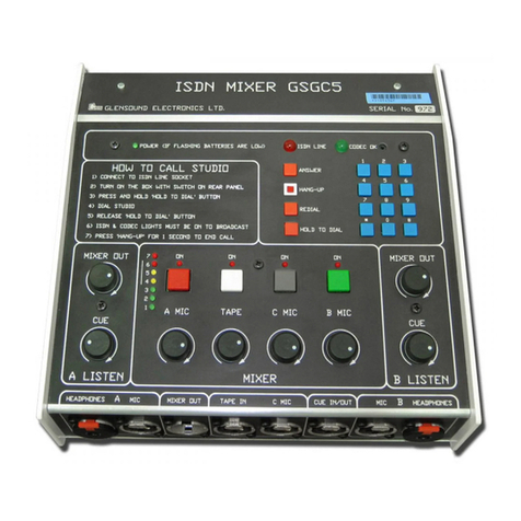
Glensound GS-GC5/USB Installation guide

GS-GC5/USB
(also covers features of GS-GC5T/USB)
USB COMMENTATOR UNIT
PRODUCT DETAILS
6 BROOKS PLACE, MAIDSTONE, KENT, ME14 1HE. ENGLAND. TEL: +44 (0) 1622 753662
Visit our Website at www.glensound.co.uk FAX: +44 (0) 1622 762330

Glensound Electronics Ltd
Thank you for choosing a new Glensound product.
All rights reserved.
Information contained in this manual is subject to change without notice, if
in doubt please contact us for the latest product information.
If you need any help with the product then we can be contacted at:
Glensound Electronics Ltd
1 – 6 Brooks Place
Maidstone
Kent
ME14 1HE
United Kingdom
Telephone: +44 (0) 1622 753662
Fax: +44 (0) 1622 762330
EMAIL ADDRESSES
General enquires: office@glensound.co.uk
Technical enquires: techinfo@glensound.co.uk
Sales enquires: sales@glensound.co.uk

PRODUCT WARRANTY:
All equipment is fully tested before dispatch and carefully designed to
provide you with trouble free use for many years.
We have a policy of supporting products for as long as possible and
guarantee to be able to support your product for a minimum of 10 years.
For a period of one year after the goods have been despatched the
Company will guarantee the goods against any defect developing after
proper use providing such defects arise solely from faulty materials or
workmanship and that the Customer shall return the goods to the
Company’s works or their local dealer.
All non wear parts are guaranteed for 2 years after despatch and any
defect developing after proper use from faulty materials or workmanship
will be repaired under this warranty providing the Customer returns the
goods to the Company's works or their local dealer.

CE
This equipment manufactured by Glensound Electronics Ltd of Brooks
Place Maidstone Kent ME14 1HE is CE marked and conforms to:
Low Voltage Directive: EN60065
Emissions: EN55103.1
Immunity: EN55103.2
WASTE ELECTRICAL AND ELECTRONIC
EQUIPMENT REGULATIONS 2006 (WEEE)
Glensound Electronics Ltd is registered for business to business sales of
WEEE in the UK our registration number is:
WEE/JJ0074UR
RoHS DIRECTIVE
EC directive 2002/95/EC restricts the use of the hazardous substances
listed below in electrical and electronic equipment.
This product conforms to the above directive and for this purposes, the
maximum concentration values of the restricted substances by weight in
homogenous materials are:
Lead 0.1%
Mercury 0.1%
Hexavalent Chromium 0.1%
Polybrominated Biphenyls 0.1%
Polybrominated Diphenyl Ethers 0.1%
Cadmium 0.01%

GS-GC5/USB Commentator Unit
Handbook Contents
Issue 1, April 2014
Description Page No.
Contents
PRODUCT WARRANTY: ........................................................................................... 3
OVERVIEW ................................................................................................................ 6
Front Panel Layout & Functions ................................................................................. 7
Rear Panel Layout & Functions .................................................................................. 9
CONNECTING THE GS-GC5/USB TO A PC ........................................................... 12
SETTING UP AUDIO FROM GS-GC5/USB TO/ FROM THE PC ............................ 12
ASIO DRIVERS ........................................................................................................ 12
AUDIO ROUTING CONFIGs .................................................................................... 13
AUDIO BLOCK DIAGRAMS OF EXISTING CONFIGs ............................................ 13
LUCI LIVE AUDIO CODEC ...................................................................................... 19
USING LUCI LIVE .................................................................................................... 19
WIRING INFORMATION .......................................................................................... 23

OVERVIEW
In this manual, the model referred to is the GS-GC5/USB. Operationally, the GS-
GC5/USB is identical to the GS-GC5T/USB, it is the box style that is different. The
GS-GC5/USB is a low, flat unit intended to sit with a laptop PC on top. The GS-
GC5T/USB is a an upright, squarer unit, with an included stand that is intended to be
used with a tablet PC. The layout of controls and connections differs slightly but
operationally the two units are identical.
The GS-GC5/USB is a high quality audio interface for broadcasters. It is powered
from internal Lithium Ion cells which can be charged from an external power supply
(just like a laptop). Internally it is a very high quality and very versatile digital mixer
whose parameters can be changed if required to match a users’ way of working.
The GS-GC5/USB also includes a licence for Luci Live*. Luci Live is a software IP
codec used by broadcasters and is compatible with other common brands of IP
codecs. When combined with the GS-GC5/USB, Luci Live is ideal for providing
remote on air contribution. *Luci Live is not included as standard with the GS-
GC5T/USB, although this can be added if required.
There are 4 audio inputs on the unit, each of which can be switched to accept a Mic
or Line level input. These 4 inputs are sent to a twin (stereo) mix bus, and each input
can be routed to both or just one channel of this mix bus. This allows the unit to be
set up as a stereo device, a mono device, or a dual mono device (for either 2
contributions or a talkback circuit).
The GS-GC5/USB also has 4 separate headphone mixes. There are 2 outputs for
each mix, one suitable for broadcast style high impedance headphones and another
for lower impedance earpieces and domestic style headphones.
The GS-GC5/USB can work as a stand alone mixer having 2 local analogue line
level outputs (whose sources are configurable), however it’s main purpose is to
connect audio into and out of laptops, netbooks etc via one of 2 very high quality
USB audio interfaces.
To allow reliable connectivity to a Local Area Network (LAN) the device has a built in
USB to LAN converter. This is to overcome the the issue of lots of modern laptops
only having WiFi network interfaces which generally are unreliable for broadcasters
to use a large events.
Front Panel Layout & Functions
PLEASE NOTE AS THE UNIT IS CONFIGURABLE IT IS POSIBLE TO CHANGE THE OPERATION
OF MOST OF THE CONTROLS SHOWN HERE. THEREFORE THE FOLLOWING IS MEANT AS A
GUIDE ONLY.
1. Channel On/ Off Switch
Turns a channel on/ off to its associated output mix
2. Channel On/ Off LED Indicator
Indicates when the LED is on that a channel is on and is being sent to its associated
output.
3. LED PPM (Top)
Indicates the outgoing level of the left channel of the mixer. For normal use the first
red LED should only occasionally illuminate.
4. LED PPM (Bottom)
Indicates the outgoing level of the right channel of the mixer.
5. L-Both-R Routing switch
This switch routes an associated source to either the left only, right only or both
outputs of the headphone amplifier.
1 2
9
3 4 65 7
8
10 11
L-BOTH-R
ON
A
ON
B
ON
D
ON
C
L-BOTH-R
L-BOTH-R
L-BOTH-R
L-BOTH-R
L-BOTH-R
L-BOTH-R
L-BOTH-R
MIX
A LISTEN B LISTEN MIXER C LISTEN D LISTEN
MIX MIX MIX
CUECUECUECUE
7654321
1 2 3 4 5 6 7
BATTERY POWERED
EXT POWERED

6. Headphone Source Routing Indication
The 2 LEDs indicate the state of the L-Both-R routing switch. The first time the L-
Both-R routing switch is pressed the 2 LEDs will indicate the current state, pressing
the L-Both-R routing switch again will toggle the next available routing option for that
circuit.
7. Headphone CUE Volume
This level control adjusts the headphone volume level of the audio that is being sent
to the CUE circuit.
8. Headphone MIX Volume
This level control adjusts the headphone volume level of the audio that I sbeing sent
to the MIX circuit.
9. Channel Gain Control
This level control adjusts the gain of the channels audio input.
10. Power On Indicators
These 2 LEDs indicate that the unit is powered on. Only 1 of the 2 LEDs will be on at
any one time. They indicate that the unit is on and from which power source it is
currently operating from. If an external power source is present then the unit will
always default to this in preference to the internal batteries.
11. Battery Level Indicator
This row of LEDs provide an accurate indication of the state of the internal batteries.
Only one LED will indicate at any one time (this is done to save power). The right
hand green LED indicates that the internal batteries are fully charged and the left
hand red LED is a warning that the batteries are virtually flat and the unit should be
connected to an external power supply.

Rear Panel Layout & Functions
PLEASE NOTE AS THE UNIT IS CONFIGURABLE IT IS POSIBLE TO CHANGE SOME OF THE
OPERATION OF SOME OF THE CONNECTORS SHOWN HERE. THEREFORE THE FOLLOWING
IS MEANT AS A GUIDE ONLY.
1. 3.5mm Domestic Headphone Jack Socket
Connect low impedance (less than 32 ohms) headphones here
2. 6.35mm Professional Headphone Jack Socket
Connect high impedance (up to 2000 Ohms) headphones here
3. Coarse Gain/ Input Type Selector Switch
This 3 position switch adjusts the input gain, source impedance and turns phantom
power on/ off to allow the associated XLR input to accept a full range of signal levels.
The graphical representation of the switch positions on the panel show the various
states of the switch.
4. XLR balanced audio input
This balanced standard 3 pin XLR audio input socket is the input for a channel of the
mixer.
5. XLR Balanced Line Output A
This balanced standard 3 pin XLR audio output plug provides an analogue output of
it’s associated source.
6. XLR Balanced Line Output B
This balanced standard 3 pin XLR audio output plug provides an analogue output of
its associated source.
1 2 3 4 5 6 7 8 9 10 11
121314
A
USB
ETHERNET
BCD
MIC / LINE INMIC / LINE INMIC / LINE INMIC / LINE IN HP
LINEMIC P48 MIC LINEMIC P48 MIC LINEMIC P48 P48 LINEMIC P48 MIC
GAIN GAIN GAIN GAIN
LINE OUT A LINE OUT B
GS-GC5-USB
19V
CE
W
SERIAL No. 001
EXT POWER
CHARGING
POWER
AUDIO &
USB AUDIO ONLY
DRIVE &
NETWORK
ABCD
HPHP HP

7. External DC Input
This is a 2 pin barrel type DC input connector. The centre pin is 2.5mm. It is wired
centre pin + Volts. It is designed to accept a +19 volt DC input and requires a 2.5
amp power supply. Most standard 19V laptop power supplies should be suitable for
this.
8. External Power On LED
This LED will be on if a suitable external DC input is connected to the external DC
input. This LED only indicates that a suitable power supply is connected it does not
indicate that the GS-GC5USB is turned on.
9. Battery Charging LED
This LED will be on if the internal Lithium Ion batteries are being charged from the
external DC power supply. The unit does not need to be turned on to charge the
internal batteries.
10. Power On LED
This LED indicates that the unit is on.
11. Power On/ Off Switch
Pushing this switch turns the unit on/ off. To prevent accidental usage during either a
broadcast or transit the switch has a long time delay on it and it must be held down
for at least 5 seconds before it will either turn the unit on or off.
12. Network Interface For Internal USB to Network Converter
Use this connector for attaching the GS-GC5USB to a network. The unit has an
inbuilt USB to Ethernet convertor. This is useful if the PC that is connected to the
GS-GC5USB only has a wireless network connection. As a general rule for
broadcast purposes it is far more reliable to use a physical wired network than a
wireless one.
13. USB Drive & Audio & Ethernet Connector
This is a USB B type connector. This connection provides digital audio to/ from your
PC and also simultaneously the data for the USB to Ethernet convertor plus it allows
access from the PC to the internal USB drive & hub. This connector should not be
used for interfacing to Apple iPads or iPhones.
****NOTE**** This is a high contact connector, meaning that it holds the inserted
cable with a lot more force than a normal connector would. This type of connector is
fitted to prevent the USB cable being accidently knocked out during a broadcast, but
it does mean that a lot more force is required to remove the USB cable from the GS-
GC/USB than may be expected.

14. USB Audio Connector
This is a standard mini USB connector. It provides only a digital audio interface to/
from the connected PC. As it provides a USB audio only interface it is possible to
use this connection to interface to an Apple iPad or iPhone via a suitable interface
cable.

CONNECTING THE GS-GC5/USB TO A PC
1. General
Connect the pc to the GS-GC5/USB using the supplied USB cable. Make sure the
PC is on and your operating system is running. Turn the GS-GC5/USB on by
pressing and holding the power on switch for at least 5 seconds. Your operating
system will find a new device and automatically install the drivers for it.
2. Checking Connectivity
In file explorer navigate to ‘This PC’. Two drives should appear 1 called ‘Luci’ and
another called GSGC5-USB. If these appear then the GS-GC5/USB will be
connected to your pc correctly.
SETTING UP AUDIO BETWEEN GS-GC5/USB & THE PC
1. USB 1 Drivers
Connecting the unit to the PC as described above will automatically install suitable
USB class 1 drivers for interfacing with Windows. Windows should automatically set
it’s audio I/O to become ‘Glensound USB audio 1.0’ if it doesn’t then search the pc or
goto ‘Manage Audio devices’ or ‘Sound’ and manually select ‘Glensound USB audio
1.0’ and set it to default.
2. Software Audio I/O selection.
Most audio software programs will set their audio I/O as per the windows default
audio I/O selection. However if you experience problems check that the sofwtare that
you are using has it’s audio I/O set to ‘Glensound USB audio 1.0’
ASIO DRIVERS
1. General
USB audio 1.0 drivers are good because they normally just work within windows and
no manual driver installation is required. However all audio into and out of your pc
will go through windows processing, this adds delay and provides potential pitfulls
(such as having the volume turned down within windows). ASIO (Audio Stream Input
Output) drivers bypass windows processing and offer a direct link between the
software and soundcard (in this case the GS-GC5/USB). ASIO drivers are generally
considerd to be far better for professional users than USB audio 1.0 drivers.
2. ASIO4ALL
The USB audio chipset that we selected for use in the GS-GC5/USB is suitable for
use with a free ASIO driver called asio4all. Just search the web for ‘asio4all’ and you
will find links to the drivers and installation guides.

AUDIO ROUTING CONFIGs
1. General
The GS-GC5/USB has a powerful audio dsp (digital signal processor) at its heart. All
the analogue audio inputs and outputs to the unit are converted to digital and are
controlled by this dsp. This means routing of the audio internally can be changed to
meet your requirements. A number of pre defined audio configs are pre installed on
the internal memory and can be selected by a user.
2. Location of Config Files
The audio routing config files are stored on the internal drive. Using file explorer
locate the drive called GSGC5-USB, in this drive you will see a number of folders all
starting with the name ‘Config’ followed by a description, for example ‘Config Dual
Mono Local Cue outs’. Each of these folders has in it a single text file called
‘settings’.
3. Selecting Which Config File To Use
When the GS-GC5/USB first turns on it reads a file called ‘Selected config’ which is a
text document and can be found using file explorer in the GSGC5-USB drive. This
‘Selected config’ text file tells the GS-GC5/USB which config to use.
To change the config simply open the ‘Selected config’ text file (we’d use Notepad,
but other text editors can be used, however once modified it must continue to be
saved as a .txt file), then change the wording of the text file to match exactly the
folder name of the config file you want to use, then save the modified file but keep
the name ‘Selected config’.
After modifying the file to start using the new config the GS-GC5/USB must be
turned off and on again.
4. Default Config
When leaving the factory the GS-GC5/USB ‘Selected config’ file will be set to default.
The default config is one that cannot be changed and is permananetly embedded in
the dsp. It’s functions are broadly the same as the config called ‘Config 4 channels
panned centre’. The purpose of the default config file is to allow the GS-GC5/USB to
still work even if no Config folders are present.
AUDIO BLOCK DIAGRAMS OF EXISTING CONFIGs
1. General
At the time of writing this manual 5 audio configs exist. Detailed below are the block
diagrams for these 5 configs along with their folder name. Any new configs that are
produced will be published as folders to copy and block diagrams for reference on
the GS-GC5/USB page of our web site www.glensound.co.uk.
****NOTE**** The block diagrams are meant only as analogue representations of
the audio flows, they do not actually represent the genuine internal digital
architecture.

Config 2 channels panned centre & stereo effects
MIC
LINE
MIC + 48v
SET GAIN
INPUT A
GAIN ON/OFF
LOW IMPEDANCE
HEADPHONES HEADPHONES
HIGH IMPEDANCE
L/B/R Switching
HEADPHONE VOLUME
MIC
LINE
MIC + 48v
SET GAIN
INPUT B
GAIN ON/OFF
MIC
LINE
MIC + 48v
SET GAIN
INPUT C
GAIN ON/OFF
MIC
LINE
MIC + 48v
SET GAIN
INPUT D
GAIN ON/OFF
MIXER
MINI USB
1 off 4 HEADPHONE AMPS A, B, C & D
LINE OUT A
LINE OUT B
USB HUB
USB AUDIO ONLY
Suitable for iPADs & iPHONEs
USB TO ETHERNET ADAPTOR NETWORK RJ45
USB 'B' SOCKET
USB AUDIO
DATA FOR ETHERNET
MEMORY
MICROPROCESSOR
LUCI LIVE
2 CHANNELS PANNED CENTRE & STEREO EFFECTS
MIX LEFT
MIX RIGHT
CUE LEFT
CUE RIGHT
PPM
PPM
MIX LEFT
MIX RIGHT
CUE LEFT
CUE RIGHT

Config 3 channels panned centre & 1 local cue in
MIC
LINE
MIC + 48v
SET GAIN
INPUT A
GAIN ON/OFF
LOW IMPEDANCE
HEADPHONES HEADPHONES
HIGH IMPEDANCE
L/B/R Switching
HEADPHONE VOLUME
MIC
LINE
MIC + 48v
SET GAIN
INPUT B
GAIN ON/OFF
MIC
LINE
MIC + 48v
SET GAIN
INPUT C
GAIN ON/OFF
MIC
LINE
MIC + 48v
SET GAIN
INPUT D
GAIN ON/OFF
MIXER
MINI USB
1 of 4 HEADPHONE AMPS A, B, C & D
LINE OUT A
LINE OUT B
USB HUB
USB AUDIO ONLY
Suitable for iPADs & iPHONEs
USB TO ETHERNET ADAPTOR NETWORK RJ45
USB 'B' SOCKET
USB AUDIO
DATA FOR ETHERNET
MEMORY
MICROPROCESSOR
LUCI LIVE
3 CHANNELS PANNED CENTRE & 1 LOCAL CUE IN
MIX LEFT
MIX RIGHT
CUE LEFT
CUE RIGHT
PPM
PPM
MIX LEFT
MIX RIGHT
CUE LEFT
CUE RIGHT

Config 4 channels panned centre
MIC
LINE
MIC + 48v
SET GAIN
INPUT A
GAIN ON/OFF
LOW IMPEDANCE
HEADPHONES HEADPHONES
HIGH IMPEDANCE
L/B/R Switching
HEADPHONE VOLUME
MIC
LINE
MIC + 48v
SET GAIN
INPUT B
GAIN ON/OFF
MIC
LINE
MIC + 48v
SET GAIN
INPUT C
GAIN ON/OFF
MIC
LINE
MIC + 48v
SET GAIN
INPUT D
GAIN ON/OFF
MIXER
MINI USB
1 of 4 HEADPHONE AMPS A, B, C & D
LINE OUT A
LINE OUT B
USB HUB
USB AUDIO ONLY
Suitable for iPADs & iPHONEs
USB TO ETHERNET ADAPTOR NETWORK RJ45
USB 'B' SOCKET
USB AUDIO
DATA FOR ETHERNET
MEMORY
MICROPROCESSOR
LUCI LIVE
4 CHANNELS PANNED CENTRE
MIX LEFT
MIX RIGHT
CUE LEFT
CUE RIGHT
PPM
PPM
MIX LEFT
MIX RIGHT
CUE LEFT
CUE RIGHT

Config Dual Mono Local Cue outs
MIC
LINE
MIC + 48v
SET GAIN
INPUT A
GAIN ON/OFF
MIC
LINE
MIC + 48v
SET GAIN
INPUT B
GAIN ON/OFF
MIC
LINE
MIC + 48v
SET GAIN
INPUT C
GAIN ON/OFF
MIC
LINE
MIC + 48v
SET GAIN
INPUT D
GAIN ON/OFF
MIXER
LOW IMPEDANCE
HEADPHONES HEADPHONES
HIGH IMPEDANCE
L/B/R Switching
HEADPHONE VOLUME
MINI USB
1 of 2 HEADPHONE AMPS A & B
LINE OUT A
USB HUB
USB AUDIO ONLY
Suitable for iPADs & iPHONEs
USB TO ETHERNET ADAPTOR NETWORK RJ45
USB 'B' SOCKET
USB AUDIO
DATA FOR ETHERNET
MEMORY
MICROPROCESSOR
LUCI LIVE
MIXER
LOW IMPEDANCE
HEADPHONES HEADPHONES
HIGH IMPEDANCE
L/B/R Switching
HEADPHONE VOLUME
1 of 2 HEADPHONE AMPS C & D
LINE OUT B
MIX 1
MIX 2
CUE 1
CUE 2
MIX 1
MIX 2
CUE 1
CUE 2
PPM
PPM

Config Dual Mono Local Mix outs
MIC
LINE
MIC + 48v
SET GAIN
INPUT A
GAIN ON/OFF
MIC
LINE
MIC + 48v
SET GAIN
INPUT B
GAIN ON/OFF
MIC
LINE
MIC + 48v
SET GAIN
INPUT C
GAIN ON/OFF
MIC
LINE
MIC + 48v
SET GAIN
INPUT D
GAIN ON/OFF
MIXER
LOW IMPEDANCE
HEADPHONES HEADPHONES
HIGH IMPEDANCE
L/B/R Switching
HEADPHONE VOLUME
MINI USB
1 of 2 HEADPHONE AMPS A & B
LINE OUT A
USB HUB
USB AUDIO ONLY
Suitable for iPADs & iPHONEs
USB TO ETHERNET ADAPTOR NETWORK RJ45
USB 'B' SOCKET
USB AUDIO
DATA FOR ETHERNET
MEMORY
MICROPROCESSOR
LUCI LIVE
MIXER
LOW IMPEDANCE
HEADPHONES HEADPHONES
HIGH IMPEDANCE
L/B/R Switching
HEADPHONE VOLUME
1 of 2 HEADPHONE AMPS C & D
LINE OUT B
MIX 1
MIX 2
CUE 1
CUE 2
MIX 1
MIX 2
CUE 1
CUE 2
PPM
PPM

LUCI LIVE AUDIO CODEC (not included with GS-GC5T/USB)
1. General
The GS-GC5/USB includes a full Windows/ Mac licence for Luci Live audio codec
software and a copy of Luci Live software is embedded within the device. The
licence does NOT cover iPhones or iPads, luci live licences for these devices must
be purchased through the relevant app store.
2. Other Software
Don’t forget that although the GS-GC5/USB includes a Luci Live licence the device
itself is a very high quality broadcast sound card and many other software packages
can be used with it.
3. Locating & Running Luci Live Software
Once the GS-GC5/USB is connected to your pc and turned on, using your file
explorer locate the folder called ‘Luci’ then open either the Windows or OSX folder, if
using windows once the Luci Windows folder has been opened look for the
application called ‘LuciLive’.
Double click on the LuciLive application to open it.
USING LUCI LIVE
1. General
LuciLive software was not written by Glensound. It was an existing software
application that was suggested by a very large customer of ours that we should
include within the GS-GC5/USB. Support for the LuciLive program should be
directed to:
Email support
iPhone: [email protected]
Windows PC: [email protected]
MAC: [email protected]
Android: [email protected]
General questions: [email protected]
Telephone support
+31 (0) 43 321 9499
The following very basic guide will help you to get started, a much better guide can
be found on the support page of the Luci website (www.luci.eu). At the time of writing
the best guide on Luci’s website was called ‘Luci Live Extended Manual incl.
Workflow for iOS. All settings incl. extended explanations how to setup new stations
and or add an existing station list’……..The title of the guide indicates that it is for
iOS not windows but the interface is so similar it is worth a read.

2. Basic Screen Shot
3. Setup Audio I/O To Luci
With LuciLive open and running select the Tools tab and select ‘Select audio I/O…’
A new window will open and assuming you’re not using the ASIO driver make sure
that you select the Input to ‘Glensound Audio 1.0 Input (Glensound USB…’ and
make sure the output is set to ‘Speakers (Glensound USB Audio 1.0), then press
OK.
Name of the Station you are
connecting to
Connect to Station, this
antenna sign must be
turned on (RED) to
send/ receive audio
Mic On, this must be
turned on (RED) to
send audio
Volume Faders.
Set both to the middle
as per this picture.
Level adjustmenst
should be done on the
GS-GC5/USB
Pressing these icons can mute headphones or
mic. If they have a line through them they are
muted and you will not hear/ send audio.
Record & Play buttons
turning play button on
can turn mic off!
This manual suits for next models
1
Table of contents
Other Glensound Recording Equipment manuals

Glensound
Glensound DARK8ADI Installation guide

Glensound
Glensound EXPRESS MKII Installation guide

Glensound
Glensound DARK1616 Installation guide

Glensound
Glensound DARK1616M Installation guide

Glensound
Glensound DANTE Vita Mini Installation guide

Glensound
Glensound BEATRICE LUCIA User manual

Glensound
Glensound SPARK Installation guide

Glensound
Glensound AOIP22 Installation guide

Glensound
Glensound DANTE DARK8MAI Installation guide

Glensound
Glensound DARK1616D Installation guide