Global Halotherapy Solutions HALO-Booth PRO MEDIUM User manual

!
HALO-Booth PRO™
MEDIUM Assembly

Thank you for purchasing the HALO-Booth PRO™ MEDIUM.
Be sure to read this assembly Manual thoroughly before beginiing assembly. Keep
instructions on händ for reference.
Table!of!Contents!
Parts ........................................................................................................................................................ 2
Tools ....................................................................................................................................................... 3
Assembly ................................................................................................................................................. 4
HALO-Fx Halogenerator™ Installation .................................................................................................... 9
HALO-Booth PRO™ MEDIUM Operation ............................................................................................... 11

© 2019 Global Halotherapy Solutions, LLC Page 2
Parts (need photos of all parts with numbers or letters)
1. Floor 1x
8. “L“ Corner
brackets 4x
2. Roof Panel
1x
9. Hinges 2x
3. Back glass
wall 1x
10. Door knob
1x
4. Front glass
door 1x
11. Bluetooth
phillips 1x
5. Side panel
front 2x
12. Bluetooth
holder 1x
6. Side panel
rear 2x
13. Volume
knob 1x
7. Side posts
2x (one will
hold Halo-
FX and has
opening;
one is solid)
14. Tablet
holder X1

© 2019 Global Halotherapy Solutions, LLC Page 3
15. Rear
photo panel
1x
18. Roof vent,
cone and sleeve
16. Rear
photo panel
holder rods
2x
19. HALOFx
halogenerator 1x
A. Body
B. Mill
C. Fan (Vent)
D. Feeder
E. Feeder
Cover
F. Scoop
G.
Transform
er
H. Optional
LED/Exhaust Vent
Wire
F- Scoop
17. White
roof panel
cover
20. Screws
A. Star tip
B. Philips
Tools
The tools you will need to assemble the HALO-Booth PRO™ MEDIUM
1. Level
2. Torque / Screw Gun
3. Philips Tips (sizes)
4. Star Tip (size)
5. Rubber Mallet
6. Step Ladder
Unpack crate carefully by using screw gun to disassemble crate FULLY. Please familiarize your self
with contents of crate. It will take 3 people 3-5 hours for assembly.
!

© 2019 Global Halotherapy Solutions, LLC Page 4
Assembly!
1. Lay Floor base (part#1) in designated location (allowing access to rear of unit when fully
built).
a. Using level, ensure floor is level. Use ‘set’ screws indicated in figure below to adjust legs if
necessary.
2. Install rear glass wall (part #3) into rear groove on floor. Be sure it is evenly centered in this
groove. Have person 1 hold upright. See figures below.
3. Install left /right rear sidewall (see parts above) by inserting into groove fully. Make sure to
not crease plastic “J” channel seal (See figure below). Secure with tape. Repeat for next side.
4. Decide which side you would like the HALO-Fx halogenerator to be on, taking outlet location
and accessability into consideration. Remove cover from outside of two side posts (part #7)
by unsrewing “L” corner brackets. See figure below(*).

© 2019 Global Halotherapy Solutions, LLC Page 5
Install side posts (part #7) to appropriate side for halogenerator placement. Make sure glass
fits in grooves evenly.
5. Install 2 front left and right side glass panels (part #5). The best way to ensure that these are
fully ‘seated’ is to place into groove at front of floor at slight angle and ‘rock’ toward post
groove as demonstrated in video. Make sure that they are securely and evenly in groove.
6. Secure side posts to floor with 2 screws (part #20). See figure below. Repeat for the other
side.
7. Place Roof Panel (Part #2) in place using two people and step ladder, lining up grooves with
the glass. Secure with screws (part #20) as in figure below.

© 2019 Global Halotherapy Solutions, LLC Page 6
8. Pull cable wires on Halogenerator side through Roof Panel (Part #2) openings. See figure
below.
9. Replace outside panels of posts using cover and “L” corner brackets from step 4. Be sure that
black power wire is exposed by pulling through cover hole. See figure below.
10. Mount the door (Part #4, see photo above). Choose left/right swing for door. Mount lower
hinge to door panel on appropriate side. Bolts must face outside.
11. Mount upper hinge (Part # 9) directly to roof panel (Part #2). See figure below.

© 2019 Global Halotherapy Solutions, LLC Page 7
12. Place glass door into ‘socket’ on floor panel (Part #1) on appropriate side and screw (Part
#20) in place lining up with upper hinge nest.
13. Place upper hinge seals and mount with hinge plate.
14. Mount hinge screw caps. Tighten posts. See figure below.
15. Mount door knob (Part #10) by screwing in place in opening in door. See figure below. Check
door seal for creases and tight seal.

© 2019 Global Halotherapy Solutions, LLC Page 8
16. Mount tablet holder on outside of door. DO NOT tighten until lined up properly. See figure
below.
17. Mount Bluetooth device holder to upper left side roof panel using 2 screws (part #12).
Retrieve volume knob from top of roof panel (it should be taped in place). Insert in the hole
marked “volume”. See figures below.
18. Mount interior scoop (part #19-F, see photo above), using knobs, onto inside posts. Scoop
will lay flat after a few uses.

© 2019 Global Halotherapy Solutions, LLC Page 9
HALO-Fx!Halogenerator™!Installation!
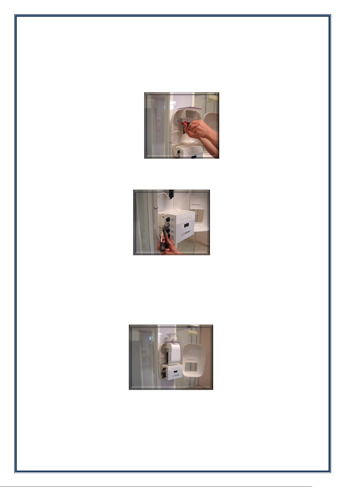
19. Open HALO-Fx halogenerator(part #19) by unscrewing cap screw. Pull black power wire
through hole in rear of halogenerator.
* Optional white wire for additional LED/vent can be tucked inside as in figure below. Secure
halogenerator using screws (part #20).
20. Attach Mill (part #19-B) using provided wing nuts. See figure below. Plug into appropriate
outlet on HALO-Fx halogenerator. Secure with Philips screwdriver.
21. Attach Fan /Vent (part #19-C) by sliding into place in front of Mill (part #19-B). See figure
below. Plug into appropriate outlet. Secure with Philips screwdriver.
22. Attach Feeder to top of HALO-Fx halogenerator. Plug into outlet on top of HALO-Fx
halogenerator. See figure below.
23. Plug black power wire into appropriate outlet on side of HALO-Fx halogenerator. Secure
using Phillips screwdriver. See figure below.
24. Connect cables on roof panel (part #2) using photo in figure below and labels on wires. Feed
light chain through hole in roof panel (part #2- see photo on next page).

© 2019 Global Halotherapy Solutions, LLC Page 10
25. Place white roof top cover panel (part #17) on top of roof panel (part #2) to hide wires.
26. Place vent hole sleeve into hole by insulation for vent. Place vent cone (part #18) into sleeve.
27. Slide very carefully into final room placement.
28. Place chair inside HALO-Booth PRO MEDIUM. Plug into standard 110 V outlet.
!

© 2019 Global Halotherapy Solutions, LLC Page 11
HALO-Booth!PRO™!MEDIUM!Operation!
1. Start HALO-Fx halogenerator (follow HALO-Fx Manual Instruction)
2. Connect Bluetooth device by pushing button on Philips Bluetooth. Adjust Volume on
Bluetooth device by turning volume knob. User can adjust volume using their connected
bluetooth device.
3. Use pull string inside to turn on additional light if desired.
Table of contents
Other Global Halotherapy Solutions Medical Equipment manuals