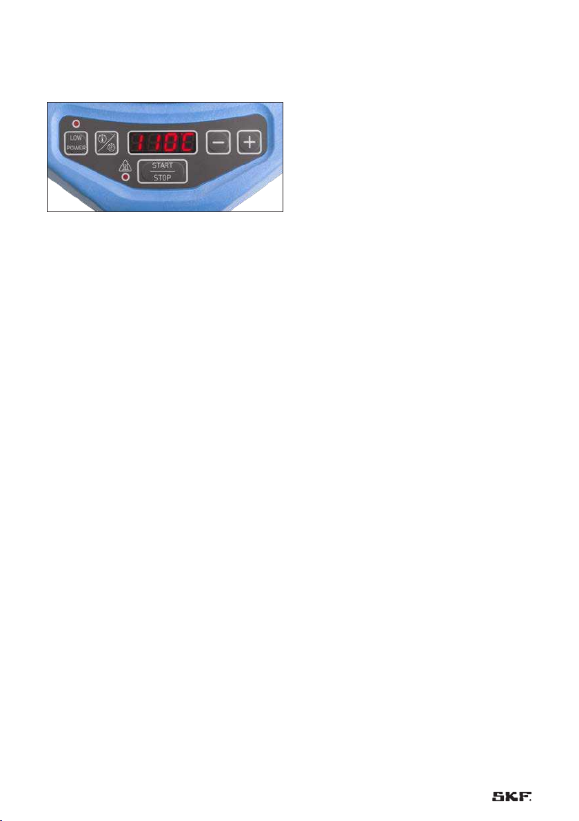
SKF TWIM 15 User manual

Instructions for use
Bedienungsanleitung
Instrucciones de uso
Mode d’emploi
Manuale d’istruzioni
Instruções de uso
Инструкция по эксплуатации
使用说明书
Betjeningsvejledning
SKF TWIM 15


1
EN English 2
DE Deutsch 16
ES Español 30
FR Français 44
IT Italiano 58
PT Português 72
RU Русский 86
ZH 中文100
DA Dansk 114

2 EN
Safety recommendations................................................................................................................. 3
EC Declaration of conformity ........................................................................................................... 3
1. Scope of delivery ...................................................................................................................... 4
2. Introduction.............................................................................................................................. 4
2.1 Principle of operation...................................................................................................................................5
2.2 Distinguishing features................................................................................................................................5
3. Description ............................................................................................................................... 6
3.1 Technical data ...............................................................................................................................................6
4. Installation ............................................................................................................................... 7
5. Preparation for use................................................................................................................... 7
6. Operation ................................................................................................................................. 8
6.1 User interface................................................................................................................................................8
6.2 Temperature mode.......................................................................................................................................8
6.2.1 Temperature measurement.............................................................................................................9
6.2.2 Change of temperature unit............................................................................................................9
6.3 Time mode ................................................................................................................................................. 10
6.4 Non-bearings mode selection.................................................................................................................10
6.5 Power level selection ................................................................................................................................ 11
7. Safety features ....................................................................................................................... 11
8. Troubleshooting...................................................................................................................... 12
9. Warning labels and safety ....................................................................................................... 14
10. Spare parts............................................................................................................................. 15
11. Maintenance and disposal ....................................................................................................... 15
Table of contents
Original instructions

3EN
Safety recommendations
• Because the TWIM 15 generates a magnetic
field, people wearing a pacemaker or implants
must not be within 5 m (16 ft) of the TWIM 15
during operation.
• During the heating process observe a safety
distance of 30 cm (1 ft) with the workpiece
or the heater. Electronic equipment, such as
wristwatches, cellphones, etc. may also be
affected.
• Always follow the operating instructions.
• Make sure that the power supply voltage does
not deviate from the acceptable range of
100 - 240V, 50 - 60Hz.
• Use the right power level, especially with
shielded or sealed with metallic inserts
bearings.
• Do not expose the TWIM 15 to high humidity,
outdoors or to flammable atmospheres.
• Do not modify the TWIM 15. All repairs should
be taken care by SKF repair shops. Do not touch
a damaged heater if plugged to the mains.
• The TWIM 15 is solely intended to heat up
bearings, gears, couplings and other industrial
annular components. It is not intended to be
used as a domestic inductive plate. Do not heat
up cooking pans or pots.
• The heater needs to be operated by
professionally trained people. Do not leave the
heater unattended. Especially when using time
mode.
• Use proper handling systems when lifting heavy
workpieces.
• Avoid contact with hot surfaces. Always wear
protective gloves. In case of burnings ask for
first aid help if necessary.
• Never heat to temperatures above 200 °C
(392 °F).
• In case of fire, do not use water nor powder-
based extinguisher. This will damage the
electronics. A CO2 based extinguisher is
recommended, if available.
• Be aware that fumes coming from the heated
element might occur.
EC Declaration of conformity
We, SKF Maintenance Products, Meidoornkade 14,
3992 AE Houten, The Netherlands herewith declare
under our sole responsibility that the products
described in these instructions for use, are in
accordance with the conditions of the following
Directive(s):
EUROPEAN LOW VOLTAGE DIRECTIVE 2014/35/EU
EMC DIRECTIVE 2014/30/EU
and are in conformity with the following standards:
EN 61000-6-2 (2005) + AC (2005) Industrial
(Immunity)
EN 55011 (2009) + A1 (2010), Class A, Group II
(Emission)
EN 61000-3-2 (2014), A (Emission)
EN 61000-3-3 (2013) (Emission)
EN 60335-1 (2012): Safety of household and
similar electrical appliances
RoHS DIRECTIVE (EU) 2015/863
EN 50581:2012
Houten, The Netherlands, June 2019
Mrs. Andrea Gondová
Manager Quality and Compliance

4 EN
1. Scope of delivery
The TWIM 15 portable induction heater contains the
following:
• Induction heater TWIM 15
• Magnetic K-type 400 mm (1.31 ft) temperature
probe TWIM 15-3
• Temperature resistant gloves TMBA G11
• Schuko plug (not mounted) in the
TWIM 15/230V version
2. Introduction
The TWIM 15 portable induction heater is designed
to heat up roller bearings that are mounted with an
interference fit onto a shaft.
Other ring-shaped metallic components can also be
heated.
The heat causes the bearing to expand, which
eliminates the need to use force during installation.
A 90 °C (162 °F) temperature difference between
the bearing and shaft is generally sufficient to
enable the installation.
At ambient temperature of 20 °C (68 °F) the bearing
must be heated to 110 °C (230 °F).
Greased and sealed bearings can be heated.
Shielded bearings or sealed bearings with metallic
insertions must be controlled as the shield or
the metallic insert might heat much faster than
the bearing itself. The reduced power setting is
recommended in these cases.

5EN
2.1 Principle of operation
The TWIM 15 portable induction heater consists
of a high temperature resistant glass filled polymer
top plate with electromagnetic coils beneath it.
When the heater is switched on, electric current
runs through these coils, generating a fluctuating
magnetic field, but no heat on the top plate itself.
However, once you set an iron or stainless-steel
component on top, the magnetic field induces many
smaller electric currents (Eddy currents) in the
component’s metal.
Fig. 1 – Magnetic field around bearing
Because iron is a poor conductor of electricity,
when all these small currents run through the iron,
much of the energy is converted into heat. Thus, on
an induction heating plate, the heat is not coming
from the top plate surface, but it is generated in the
component itself. This makes heating a lot more
efficient than other heating methods.
The drawback is that only components made from
iron will work with induction plates. Components
made of only copper or aluminum conduct electricity
too good to generate significant heat. Cast-iron and
stainless-steel work fine. A rule of thumb is: if a
magnet sticks to the component, the inductive plate
will heat it up. Nonetheless, small brass or copper
rings (such as shields or bearing cages), due to its
small mass, might heat much faster than the rest of
the bearing and a low power setting must be always
chosen.
2.2 Distinguishing features
• Portable:
Thanks to the medium frequency technology
used and the right choice of materials, the
heater is light weight. This, together with the
built-in handle, makes it portable to use it in
different locations or to easily store it in a locked
place.
• Innovative heating of bearings:
Thanks to the smart construction and operating
software of the heater, a low temperature
difference in between the inner ring and outer
ring of the bearing is achieved. This reduces the
internal tensions generated due to the excessive
thermal expansion of the inner ring compared
to the one of the outer ring.
• Versatile:
Thanks to the flat shape of the induction plate,
the user no longer must choose which yoke is
needed for every component. This increases
the number of different components that you
can heat up on the plate and at the same time
reduces the number of accessories needed.
• Quiet:
Due to the medium frequency technology the
heating of components does not make noise.
An LED indicates when the heater is heating,
even if you cannot hear it. A fan might be heard
after some use. This helps to cool down the
electronics.
• Power regulation:
Thanks to the different power settings, the
heater can heat up sensitive components at a
slower pace or other than bearings.

6 EN
3. Description
The operation of the heater is controlled by the
internal electronics in two modes.
The operator can either select the desired
temperature of the bearing in Temperature Mode or
set the length of time that the bearing or component
will be heated in Time Mode. The power level can
be adjusted to Low Power Mode for slower heating
of sensitive workpieces (for example, bearings with
shields or metallic inserts in the seals).
3.1 Technical data
Designation TWIM 15/230V, TWIM 15/110V
Max. bearing weight * 20 kg (44 lb)
Min. bearing bore diameter 20 mm (0.79 in)
Max. bearing outer diameter 320 mm (12.6 in)
Max. bearing width 85 mm (3.35 in)
Performance examples
(bearing, weight, temperature, time)
6320: 7,1 kg (15,7 lb), 110 ˚C (230 ˚F), 320 seconds
22320 CC/W33: 12,8 kg (28.2 lb), 110 ˚C (230 ˚F),755 seconds
Maximum power TWIM 15/230 V: 2,3 kVA
TWIM 15/110 V: 1,8 kVA
Voltage TWIM 15/230 V: 230 V, 50 Hz
TWIM 15/110 V: 110 V, 60 Hz
Max. current consumption TWIM 15/230 V: 10 A
TWIM 15/110 V: 16 A
Temperature control 20 - 200 ˚C (68 - 392 ˚F)
Demagnetisation The heater does not magnetise
Dimensions (w × d × h) 450 × 500 × 100 mm (17.7 ×19.7 ×3.9 in)
Total weight 6,6 kg (14.6 lb)
* Depending on the geometry of the bearing, maximum heating temperature and power availability.

7EN
4. Installation
A qualified electrician must install a suitable plug.
Make sure that the line voltage is within the
specified range depending on the heater type.
TWIM 15/230V 230V, 50Hz
Mains supply terminal Cable color
Neutral Blue
Line Brown
Ground Not connected
TWIM 15/110V 110V, 60Hz
Mains supply terminal Cable color
Neutral White
Line Black
Ground Not connected
IMPORTANT:
The main switch in the heater is not a safety switch.
The heater needs to be unplugged from the mains
to perform any repair.
If the mains cable is damaged, it must be replaced.
5. Preparation for use
• Place the TWIM 15 in horizontal position on a
surface.
• Connect the mains plug to a suitable power
supply.
• Carefully place the workpiece to be heated in
the center of the top plate.
• The heater is designed to heat up one
component at a time.
• If used in Temperature Mode, plug the
temperature probe into the connector.
Place the magnetic tip of the probe on the
horizontal surface of the bearing inner ring or
on the innermost surface of the workpiece.
• Switch on the heater from the main switch,
which is located at the rear right of the heater.
The power LED will be lit for few seconds until
the entire display and heater will be ready.
• Select the right heating mode and settings.
• Once you have finished heating the component,
attach the magnetic probe tip to the metallic
sheet on the heater’s housing. This is the
temperature probe’s parking spot, located at the
rear left of the heater.

8 EN
6. Operation
6.1 User interface
Fig. 2 – User interface
From left to right:
• The LOW POWER button and LED.
This button reduces the power of the heater by
half of what it would normally take.
If low power mode is selected, then the red LED
is switched on.
• The temperature/time symbols button is the
MODE button. This button shifts in between
Temperature Mode and Time Mode.
• LED display. The process information is
displayed here: goal temperature, actual
temperature, error codes, time, etc.
• MINUS and PLUS buttons. These buttons
decrease or increase the value shown on the
LED display.
• START/STOP button and heating LED.
Press to start or stop the heater. The LED
button is permanently ON when the heater is
heating.
6.2 Temperature mode
In this mode components can be heated to a given
temperature.
• If the LED screen shows °C or °F,
Temperature Mode is selected.
• The selected temperature is shown on the
display. The default temperature for bearings
is 110 °C (230 °F). If a different temperature is
desired, press + or – to adjust the temperature
in steps of 1˚. Keep the + or – buttons pressed
for a faster adjustment.
• It may be desirable to heat up bearings or other
components to temperatures above 110 °C
(230 °F) for an increased mounting time or
a tighter interference fit. Consult the bearing
specifications to determine the maximum
permitted temperature. Always ensure that
the bearing does not lock due to an excessive
expansion of the inner ring compared to the
outer ring.
• Make sure that the temperature probe is
mounted on the bearing inner ring flange.
• Press START/STOP to start the heater.
The heating LED will switch on. Even if you
cannot hear it, the component is being heated.
• The user interface displays the temperature
detected by the temperature probe.
• Temperature differences in between top
and bottom might occur. This is due to the
higher influence of the inductive coils on the
bottom part of the component. This effect is
automatically adjusted in the last stages of the
heating.
• During heating, when pressing the MODE
button, the heating time is shown.
• When the selected temperature has been
reached, the bearing is then ready to be taken.
An acoustic signal will be generated for
4 seconds.
• If the component is not removed nor the
process stopped, the temperature holding
feature will maintain the component at
temperature for 10 minutes.
• By removing the temperature probe or
the workpiece, the heating process will
automatically stop. It can also be stopped by
pressing the START/STOP button.
• Remove the workpiece with proper handling
equipment. Do not slide the hot component
over the user interface surface as this will
damage the heater.
• The heater is now ready to heat up another
workpiece with the same settings.

9EN
• Depending on the size of the bearing, the
temperature probe might take some time to
register the first temperature increase.
This is because the heat is mainly coming from
the bottom part of the bearing and the heat
takes some time to be transferred to the top.
IMPORTANT:
The TWIM 15 can heat up components up to
200 °C (392 °F). Heating above these temperature
(by for example using Time Mode) can damage the
heater.
6.2.1 Temperature measurement
• When the heater is not operating, the
temperature of the workpiece can be measured
by pressing MODE and START/STOP at the
same time. Press any button to cancel the
temperature measurement.
• The temperature probe is a valuable part of
the heater. Treat it with care and after use, we
suggest that it is placed on the probe’s parking
spot in the rear left of the heater to avoid
damages on it.
• The surface of the workpiece where the
temperature probe is located should be clean,
dry and flat. Measuring on dirty, wet or curved
surfaces will give wrong temperature readings
and may result in overheating the workpiece or
even damaging the heater.
• When heating one component after another
in warm environments or with very high
temperature settings, the temperature probe
might need some extra time to cool down
before starting a new heating job.
Error code E06 might be triggered then. If this
happens, simply allow some cooling time on a
cold surface.
6.2.2 Change of temperature unit
Press MODE and “+” at the same time to change in
between °C to °F.
Once a heating cycle is completed, the temperature
unit setting remains the same even after
disconnecting the heater from the mains power.

10 EN
6.3 Time mode
This mode is suitable for batch production, when
the time required to heat a workpiece to a given
temperature is already known. It is also used in
emergency cases, when the temperature probe
is missing or defective. The temperature of the
workpiece must be then checked using an external
thermometer, like a TKDT 10.
Not monitoring the temperature might result
in damages on the top plate due to too high
temperatures.
• If the user interface display shows °C or °F,
press the MODE button to select Time Mode.
• Press + or – to adjust the time.
• Press the START/STOP button to start the
heater. The display will show the remaining
time.
• Whilst heating, the temperature measured
by the probe (if attached) can be displayed by
pressing the MODE button. When pressed again
it displays the remaining time again.
• When the time has elapsed, the heating stops,
and an acoustic signal is generated for
4 seconds.
• Remove the workpiece with proper handling
equipment.
• The TWIM 15 is now ready to heat another
workpiece with the same settings.
IMPORTANT:
The TWIM 15 can heat up components up to
200 °C (392 °F). Do not use Time Mode to go above
200 °C (392 °F). Heating above these temperatures
might damage the heater.
Do not leave the heater unattended in Time Mode.
6.4 Non-bearings mode selection
A non-bearing mode is available. In this mode all
the power is mainly focused on the innermost part
of the component, where the interference fit with
the shaft will be.
This mode is intended to make the heating of
non-bearings faster; however, it might occur that
this benefit is not accomplished due to the specific
geometry of the workpiece to be heated.
The normal modes are designed for bearings.
In these cases, the TWIM 15 is heating the inner
and outer ring independently to maintain a small
temperature difference and avoid internal tensions
due to an excessive thermal expansion of the inner
ring compared to the outer ring.
• Press the LOW POWER and the “+” buttons
at the same time to enable the non-bearings
mode. Once selected, the Low Power LED will
be blinking.
• Now, Time or Temperatures modes can be
selected.
• The maximum heating temperature capacity
of the heater depends on the dimensions and
weight of the component. In case of doubt,
consult with your SKF specialist.
• Press the LOW POWER and the “+“ buttons
again to deactivate the mode.

11EN
6.5 Power level selection
The shape, weight, size and internal clearances, all
affect to the time required to heat up a bearing. The
large variety of bearings precludes the possibility of
providing a specific power level setting for each type.
Instead, the following guidelines are provided:
• In the case of shielded or sealed bearings with
metallic inserts, the LOW POWER mode must
be always selected. Light metallic rings can heat
up much faster than the rest of the component.
This might damage the bearing or the heater
itself due to too high temperatures.
• In the case of very small bearings, the power of
the TWIM 15 is automatically lowered.
If too fast heating is detected, the LOW POWER
mode must be selected. If the component
heats up faster than what can be read by the
temperature probe, the component might reach
temperatures above the desired level.
• In the case of the TWIM 15, heating bearings
with a tight internal clearance (C1 or C2) or
preloaded bearings is not an issue.
If a too high temperature difference is detected,
the LOW POWER mode must be selected.
Slow heating ensures that the bearing expands
evenly, thereby preventing damage to the
bearing.
7. Safety features
The TWIM 15 is equipped with the following safety
features:
• Automatic overheating protection of the
heater. The heater has several internal
temperature sensors to protect itself. In case
that the temperature measured by one of them
is too high, measures are automatically taken to
stop this. For example, the heater might lower
the power or stop. In any case, the user must
monitor the process since too fast temperature
increases might not be detected on time.
• Over current protection.
The heater has a built-in fuse.
• Too hot surface warning.
A “hot” message in the screen will be shown
when the temperature of the surface of
the top plate will be above 60 °C (140 °F)
approximately.
• Faulty temperature probe detection.
In Temperature Mode, the heater will give an
error and stop if no temperature increase is
detected.
NOTE:
To increase the time to error E05 by a 50%, press
the “Mode” and the “-“ buttons simultaneously.
“t1.5” will be shown on the display briefly when this
is activated and “t1.0” when deactivated again.
This setting has to be chosen for every individual
heating job.

12 EN
8. Troubleshooting
It might happen that you encounter a failure in the
heater. If this happens, have a look to the following
options:
• The heater does not start at all. Make sure that
the heater is properly connected to the power
supply and that the fuse holder is properly
mounted. If the fuse holder is slightly out of
place, no current will pass through.
Error code Fault Action to fix it
E00 No workpiece detected
- Too small workpiece
- During heating, the workpiece has
been moved
- Make sure that the workpiece is
within the operating range (weight
and size)
- Place it centered and don’t move it
during the heating.
E01 Hardware defect
- No communication from internal
electronics
- Wiring damage
Return to reseller
E02 Fan Failure
- Damaged fan
- Fan wiring damaged
Return to reseller
E03 Overheated coils
- Too intense use without time to
cool down
- At start, coil temperature sensor
damaged
- Remove workpiece
- Do not switch off the heater
to allow the fan to cool the
heater down. The error will be
automatically cleared
- Otherwise, return to reseller
E04 Power electronics overheated
- Too intense use without time to
cool down
- Remove workpiece
- Do not switch off the heater
to allow the fan to cool the
heater down. The error will be
automatically cleared
- Otherwise, return to reseller
E05 Too slow temperature increase
- Temperature probe not attached
to the component
- Workpiece out of range (too big
or heavy for heating capacity)
- Make sure that the thermocouple
is mounted correctly (to a flat,
clean surface)
- Increase the safety time to error
by pushing MODE & “-“
simultaneously for big
components
• A system fault will be indicated by an acoustic
signal and one of the following fault codes on
the user interface display will be shown:

13EN
Error code Fault Action to fix it
E06 Missing or Invalid Thermocouple
- Temperature probe not connected
or damaged
- Temperature probe removed
during operation
- Temperature probe still cooling
down from a previous heating job.
- Check Thermocouple connection
and wire damage
- If damaged, use Time Mode and
use an external thermometer
- Do not remove the probe during
operation.
- Allow some cooling time until
temperature probe reading
stabilization.
E07 Power electronics failure
- Electronics disturbance
- Electronic damage
- Reset the heater
- Replace power print
(send to reseller)
E08 Mains supply voltage out of range
- Eventual voltage peak
- Power supply out of tolerance (10%)
- Reset the heater
- Check mains supply for correct
level
E10 Environment Temperature
out of range
- Operating range in between
0 - 40 °C (32 -104 °F)
- Make sure the heater is within
temperature range
- Use it indoors and avoid sun
E11 No calibration data
- Electronics failure
- Return for re-calibration
E12 Wrong voltage supply
- Voltage out of calibration range
- Check the voltage version of the
heater
- Check the voltage of the power
supply

14 EN
9. Warning labels and safety
Warning label Meaning
Use heat protection gloves
In case of burning your fingers, get first aid help if necessary.
Risk of pinching your fingers
Special care needs to be taken into account when positioning components on the heater
or transporting them.
Always read the instructions for use
Electro-magnetic field radiation
The heater emits a magnetic field and a distance of 30cm (1ft) needs to be kept in
between the user and the heater when heating.
Risk if metallic implants in the user’s body
Due to the magnetic field, people with implants should take
extra safety distance.
Hot surfaces
There are hot surfaces on the heater such as the heated element, but also
the heater itself might get hot. Take the right preventive measurements.
Risk for people wearing pacemakers
Due to the magnetic field, people wearing pacemakers should take
extra safety distance.

15EN
10. Spare parts
Spare parts Description
TWIM 15-3 Magnetic K-type probe 400mm (1.31 ft)
11. Maintenance and disposal
• Store the heater in a dry area, with low
humidity (0-95% non-condensing).
• Store and transport the heater within a
temperature range of 0- 50 °C (32 - 122 °F).
• Keep the heater clean with a soft dry cloth.
Remove all oil drippings that might remain after
use.
• The heater does not require any specific
maintenance nor regular calibration.
• Do not try to fix the heater yourself.
Approach your SKF contact person or distributor
if there is any malfunctioning or preventive
repair needed.
• The heater is calibrated during production.
If some repairs are performed, the heater needs
to be recalibrated.
• In case of disposal of the heater, take the
necessary measurements to recycle it.
Do not dispose it in a general waste bin.

16 DE
Sicherheitshinweise ...................................................................................................................... 17
CE Konformitätserklärung ............................................................................................................. 17
1. Lieferumfang .......................................................................................................................... 18
2. Einleitung ............................................................................................................................... 18
2.1 Funktionsweise ..........................................................................................................................................19
2.2 Unterscheidungsmerkmale......................................................................................................................19
3. Beschreibung.......................................................................................................................... 20
3.1 Technische Daten ......................................................................................................................................20
4. Einbau ................................................................................................................................... 21
5. Vorbereitung für die Verwendung ............................................................................................ 21
6. Bedienung .............................................................................................................................. 22
6.1 Benutzeroberfläche................................................................................................................................... 22
6.2 Temperatur-Modus................................................................................................................................... 22
6.2.1 Temperaturmessung......................................................................................................................23
6.2.2 Wechsel der Temperatureinheit....................................................................................................23
6.3 ZEIT-Modus................................................................................................................................................ 24
6.4 Auswahl des Nicht-Lager-Modus...........................................................................................................24
6.5 Leistungspegelauswahl............................................................................................................................. 25
7. Sicherheitsfunktionen ............................................................................................................. 25
8. Schadensbehebung................................................................................................................. 26
9. Warnschilder und Sicherheit ................................................................................................... 28
10. Ersatzteile............................................................................................................................... 29
11. Instandhaltung und Entsorgung............................................................................................... 29
Inhalt
Übersetzung der Original-Bedienungsanleitungen

17DE
Sicherheitshinweise
• Weil das TWIM 15 ein Magnetfeld erzeugt,
dürfen sich Menschen mit Herzschrittmacher
während des Betriebs nicht innerhalb von 5 m
des TWIM 15 aufhalten.
• Während des Anheizungsprozesses ist ein
Sicherheitsabstand von 30 cm zum Werkstück
oder dem Anwärmgerät einzuhalten.
Elektronische Geräte, wie z.B. Armbanduhren,
Mobiltelefone usw. können ebenfalls betroffen
sein.
• Alle Anweisungen befolgen.
• Achten Sie darauf, dass die
Versorgungsspannung nicht vom zulässigen
Bereich von 100 - 240 V, 50 - 60 Hz abweicht.
• Verwenden Sie die richtige Leistungsstufe,
insbesondere bei Lagern mit Deckscheiben oder
mit Metalleinsätzen.
• Halten Sie das TWIM 15 von hoher
Luftfeuchtigkeit oder entzündlichen
Atmosphären fern und benutzen Sie es nicht im
Freien.
• Nehmen Sie am TWIM 15 keine Modifizierung
vor. Reparaturen dürfen nur von einer
qualifizierten SKF Werkstatt durchgeführt
werden. Berühren Sie kein beschädigtes
Anwärmgerät, wenn es an das Stromnetz
angeschlossen ist.
• Das TWIM 15 ist ausschließlich zum Anwärmen
von Lagern, Zahnrädern, Kupplungen und
anderen industriellen Ringkomponenten
bestimmt. Es ist nicht für die Verwendung
als induktive Haushaltsplatte vorgesehen.
Erwärmen Sie keine Kochpfannen oder -töpfe.
• Das Anwärmgerät muss von professionell
ausgebildeten Personen bedient werden. Das
Anwärmgerät nicht unbeaufsichtigt lassen. Dies
gilt insbesondere bei Verwendung des Timers.
• Zum Anheben schwerer Werkstücke geeignete
Arbeitsgeräte verwenden.
• Kontakt mit heißen Flächen vermeiden.
Stets Schutzhandschuhe tragen. Bei
Verbrennungen ggf. Erste Hilfe anfordern.
• Niemals auf Temperaturen über 200 °C
erwärmen.
• Im Brandfall kein Wasser oder Pulverlöschmittel
verwenden. Dadurch wird die Elektronik
beschädigt. Stattdessen wird ein CO2-
Feuerlöscher empfohlen (sofern vorhanden).
• Beachten, dass das angewärmte Element
Dämpfe absondern kann.
CE Konformitätserklärung
Die SKF Maintenance Products, Meidoornkade 14,
3992 AE Houten, Niederlande erklärt hiermit unter
unserer alleinigen Verantwortung, dass die in dieser
Gebrauchsanweisung beschriebenen Produkte den
folgenden Richtlinien und Normen entsprechen:
EUROPÄISCHEN NIEDERSPANNUNGSRICHTLINIE
2014/35/EU
EMV-Richtlinie 2014/30/EU
außerdem stimmen sie mit den folgenden Normen
überein:
EN 61000-6-2 (2005) + AC (2005) Störfestigkeit
für Industriebereiche
EN 55011 (2009) + A1 (2010), Klasse A, Gruppe II
(Emission)
EN 61000-3-2 (2014), A (Emission)
EN 61000-3-3 (2013) (Emission)
EN 60335-1 (2012): Sicherheit von
Haushaltsgeräten und ähnlichen Elektrogeräten
RoHS-Richtlinie (EU) 2015/863
EN 50581:2012
Houten, in den Niederlanden, Juni 2019
Mrs. Andrea Gondová
Manager Quality and Compliance

18 DE
1. Lieferumfang
Das tragbare Induktions-Anwärmgerät TWIM 15
beinhaltet:
• Induktions-Anwärmgerät TWIM 15
• Magnetischer Temperaturfühler TWIM 15-3,
400 mm, K-Typ
• Wärmebeständige Handschuhe TMBA G11
• Schukostecker lose beigelegt bei der
TWIM/230V Version
2. Einleitung
Das tragbare Induktions-Anwärmgerät TWIM 15 ist
zum Anwärmen von Rollenlagern bestimmt, die mit
Presspassung auf einer Welle montiert sind.
Auch andere ringförmige metallische Bauteile
können angewärmt werden.
Die Hitze verursacht ein Expandieren des Lagers,
was die Notwendigkeit einer Kraftanwendung
während des Einbaus beseitigt. Eine
Temperaturdifferenz von 90 °C zwischen Lager
und Welle ist im Allgemeinen ausreichend, um den
Einbau zu ermöglichen.
Bei einer Umgebungstemperatur von 20 °C muss
das Lager auf 110 °C erwärmt werden.
Geschmierte und abgedichtete Lager können
erwärmt werden. Lager mit Deckscheiben oder
abgedichtete Lager mit metallischen Einsätzen
müssen kontrolliert werden, da sich die Deckscheibe
oder der metallische Einsatz wesentlich schneller
erwärmen kann als das Lager selbst. In diesen
Fällen ist zu empfehlen, die Einstellung mit
reduzierter Leistung zu wählen.
Table of contents
Languages:
Other SKF Heater manuals
Popular Heater manuals by other brands

Dimplex
Dimplex OCR2000 manual

Proton
Proton EX30 Operation manual

HearthRite
HearthRite HB20ML-1 OWNER'S OPERATION AND INSTALLATION MANUAL

STIEBEL ELTRON
STIEBEL ELTRON CK 15 E Operation and installation

Rapid Engineering
Rapid Engineering CGTH-30 Installation & operation manual

VTS Medical Systems
VTS Medical Systems WING W100-200-EC manual