Oval Delta Flowpet FLX B Series User manual

1
Ins. No. D-555-3-E
MODEL : FLX£££−£££B
Vortex Flowmeter
DELTA FLOWPET
Every OVAL vortex owmeter DELTA FLOWPET is fabricated and shipped from our factory under stringent
quality control. In order to maintain its design performance throughout its life, this manual offers the operator
the necessary installation, operation and maintenance information. Be well familiar with these instructions
before you place the meter in service and keep this manual at the eld location for ready reference.
High temperature type
(radiator ns provided)
Standard type

D-555-3-E
2
CONTENTS
1. BEFORE YOU BEGIN............................................................................................. 4
1.1 Conrming the Nameplate .............................................................................................................4
1.2 Transportation Considerations.......................................................................................................4
1.3 Storage Considerations .................................................................................................................4
2. OPERATING CONDITIONS.................................................................................... 5
3. GENERAL ............................................................................................................... 5
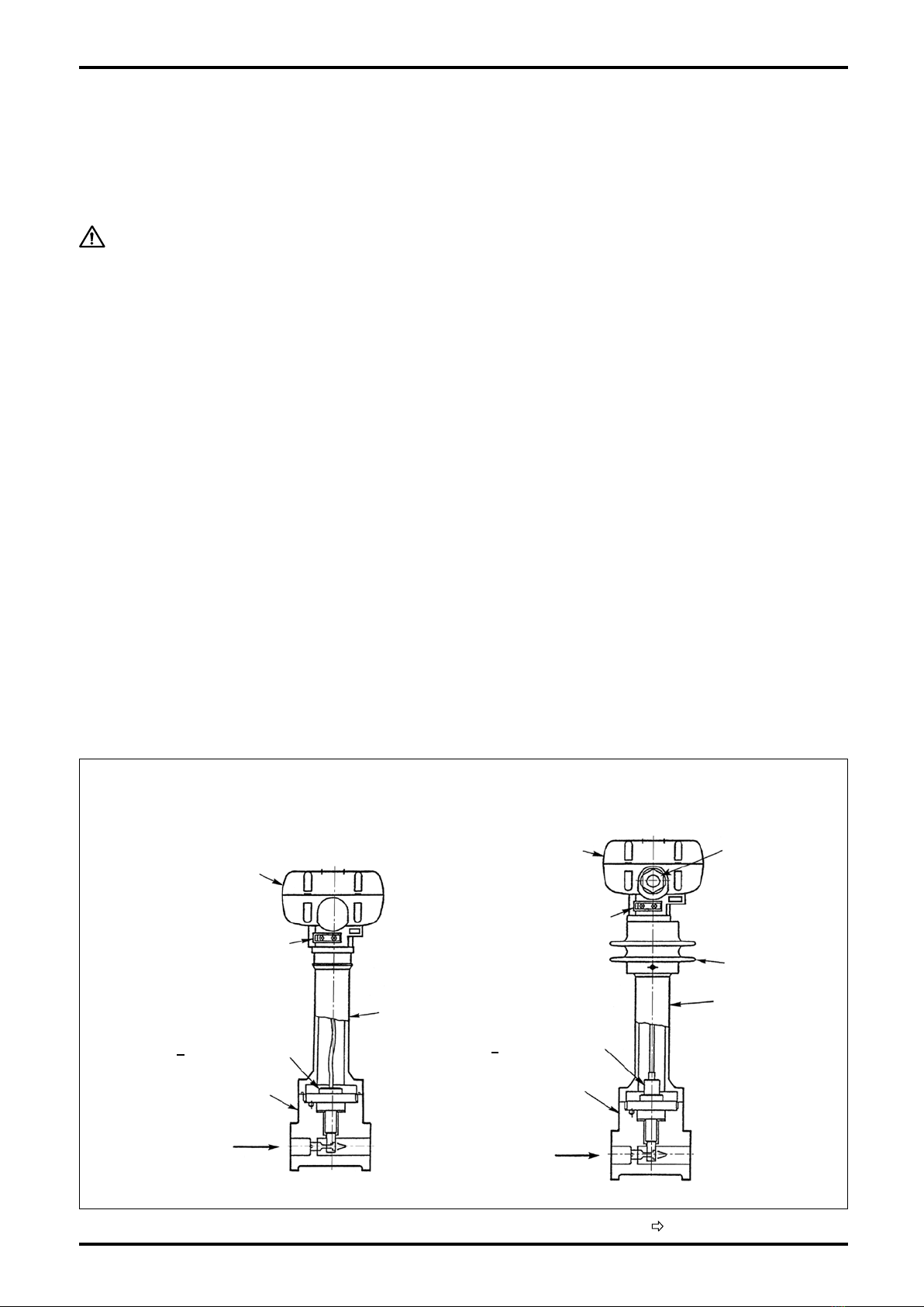
4. PART NAMES AND FUNCTIONS .......................................................................... 5
4.1 Part Names ....................................................................................................................................5
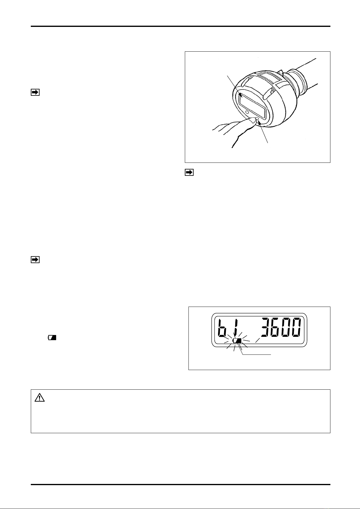
4.2 Display Functions and Operation...................................................................................................7
4.2.1 Display Menu Selection ...........................................................................................................7
4.2.2 About the Displayed Messages during Operation ...................................................................7
4.2.3 Total Counter Reset .................................................................................................................8
4.2.4 About the Measurement Units .................................................................................................8
4.2.5 Low Battery Alarm Indication...................................................................................................8
5. PIPING INSTRUCTIONS ........................................................................................ 9
5.1 Standard Piping Conditions ...........................................................................................................9
5.2 Pipes to be Used..........................................................................................................................11
5.3 Location of Pressure Gauge and Thermometer Taps ..................................................................11
5.4 Pulsations ....................................................................................................................................11
5.5 Prevention of Cavitation (liquid service).......................................................................................11
5.6 Prevention of Excessive Flowrate ................................................................................................12
5.7 Prevention of Slug Flow ...............................................................................................................12
5.8 Partially Filled Pipe.......................................................................................................................12
5.9 Bypass Line..................................................................................................................................12
6. INSTALLATION ..................................................................................................... 13
6.1 Installation Location .....................................................................................................................13
6.2 Physical Orientation .....................................................................................................................13
6.3 How to Change Preamplier Orientation................................................................................................. 13
6.4 Lagging Work ...............................................................................................................................13
6.5 Installation Procedure ..................................................................................................................14
6.6 Wiring Diagrams...........................................................................................................................15
7. OPERATION.......................................................................................................... 16
7.1 Flushing the Piping Assembly......................................................................................................16
7.2 Operation Procedure....................................................................................................................16
8. ABOUT CONFIGURATION OF PARAMETERS ................................................... 17
8.1 Parameters List ...........................................................................................................................17
8.2 Parameter Setup Procedure.........................................................................................................19
8.2.1 Procedure to modify a parameter ..........................................................................................19
8.2.2 Procedure to Enter a Parameter ............................................................................................19
8.2.3 About Alarm Outputs .............................................................................................................22
8.2.4 About Dummy Output Functions (special functions) .............................................................23
8.2.5 Parameter Initialization...........................................................................................................23
8.3 About the Error Messages ...........................................................................................................24
Table 8.4 Menu Trees and Switch Operation ..................................................................................25

D-555-3-E
3
9. MAINTENANCE .................................................................................................... 26
9.1 Sensor Replacement....................................................................................................................26
9.1.1 Sensor Unit Removal, Standard Type ........................................................................................ 26
9.1.2 Sensor Unit Removal, High-Temperature Type ......................................................................27
9.1.3 Sensor Unit Installation ..........................................................................................................28
9.2 Preamplier Inspection ................................................................................................................29
9.2.1 Switches, Potentiometers, and Test Pins...............................................................................29
9.3 Battery Pack Replacement ..........................................................................................................30
10. EXPLODED VIEW AND PARTS LIST................................................................. 31
10.1 Exploded View ...........................................................................................................................31
10.2 Parts List ....................................................................................................................................32
11. GENERAL SPECIFICATIONS............................................................................. 33
11.1 General Specications ...............................................................................................................33
11.2 Displayed and Output Units (default settings) ...........................................................................34
11.3 Pressure Losses.........................................................................................................................34
12. PRODUCT CODE EXPLANATION ..................................................................... 35
13. OUTLINE DIMENSIONS..................................................................................... 36
13.1 DELTA FLOWPET .......................................................................................................................36
13.2 Flow Straightener and Downstream short Pipe .........................................................................38
This manual uses the precaution words "NOTE", "CAUTION", and "WARNING" as explained
below:
NOTE: Notes are separated from the general text to bring the user's attention to
important information.
CAUTION: Caution statements inform the user of hazards or unsafe practices which could
result in minor personal injury or product/property damage.
WARNING: Warning statements inform the user of hazards or unsafe practices which could
result in severe personal injury or death.

D-555-3-E
4
1. BEFORE YOU BEGIN
Every DELTA FLOWPET is thoroughly inspected and tested before it leaves the factory. When received, its
appearance should thoroughly be inspected for any indication of damage by rough handling during transit.
Necessary handling precautions are described in this section; read the instructions carefully.
For any inquiries, contact your nearest OVAL designated sales ofce.
As for other information, nd the respective section.
NOTE: When you make inquiries, include the product name, model number, stock number, ratings and
other pertinent information.
1.1 Confirming the Nameplate
DELTA FLOWPET is assembled and adjusted
according to individual customer specifications.
Product code and ratings appear on the meter
nameplate (tag) attached on the side of preamplier.
Make sure that the ratings shown conform to your
particular specications.
1.2 Transportation Considerations
(1) It is desirable that DELTA FLOWPET be transported to the installation site in the shipping container used for
transit from the factory.
(2) DELTA FLOWPET is adjusted and inspected as one complete assembly consisting of the owmeter body,
sensor subassembly (owrate detection), and preamplier.
Be sure to treat them as an integral assembly.
1.3 Storage Considerations
If DELTA FLOWPET upon receipt is to be stored for long periods of time before installation, unexpected faulty
conditions could arise. If a long-term storage is anticipated, take the following precautions:
(1) Keep the equipment in store in the same shipping container used for transportation from OVAL if possible.
(2) Place of storage should conform to the following requirements:
- Free from rainwater and moisture.
- Free from vibration and impact shocks.
- Temperature and relative humidity in the storage place are at or near room temperature and humidity (around
25°C and 65%)
(3) Purge the DELTA FLOWPET that has once been placed in service with clean air, N2 gas, etc. to prevent the
process uid from adhering to the meter body, connections, pipe walls, housing and so on before storage.
(Wash clean with suitable detergent if necessary.)
CAUTION: Do not use solvents, such as thinner or alcohol, for cleansing.
(4) For long-term storage, it can best be stored in the shipping container used for transportation from the
factory.
Nameplate (tag)

D-555-3-E
5
2. OPERATING CONDITIONS
To maintain the stated accuracy and life, it is necessary that the owrate, pressure, temperature and other
variables be held within the ratings specied.
Make sure of these ratings stated in the specications supplied with the product.
The owmeter's preamplier housing is made from polycarbonate; avoid exposure to the direct rays of the sun.
CAUTION: DELTA FLOWPET is a non-explosionproof product and not serviceable
in a hazardous location.
3. GENERAL
DELTA FLOWPET is a vortex flowmeter, using a piezoelectric sensor. Behind the bluff body located
perpendicular to the uid ow, von Karman vortices form and shed proportional to the rate of ow. DELTA
FLOWPET picks up these vortices with the piezoelectric sensor for owrate measurement.
DELTA FLOWPET Features
(1) Wide ow range and high meter accuracy.
(2) Sensor isolated from the process uid and simple design with no moving parts offers long service life.
(3) Free from degradation in accuracy with age.
(4) Broad temperature and pressure range. Accepts most uids, including liquid, gas, and steam.
(5) Small pressure loss saves energy.
(6) As remote outputs, you can select alarm outputs, a pulse output, or analog output.
(7) A large LCD display: separating the selector magnet from the display and holding it close to "MODE" or
"RESET" switch enables you to switch from total ow to instantaneous owrate, or vice versa.
(8) The display can be rotated to any orientation for maximum viewability.
4. PART NAMES AND FUNCTIONS
4.1 Part Names
(Continued on next page.)
Fig. 4.1 Part Names
• Standard Type
(operating temp. -10 to +80°C)
• High-temp. Type
(operating temp. -10 to +200°C)
Flow Direction
(4) Preamplier
(4) Preamplier
(5) Preamp Disconnect
Lever
(5) Preamp Disconnect
Lever
(3) Adapter (3) Adapter
Signal Cable
(one meter long
furnished)
Radiator Fins
(2) Sensor
(vortex sensor)
(2) Sensor
(vortex sensor)
(1) Meter Body
Probe
[
(1) Meter Body
Flow Direction
Probe
[

D-555-3-E
6
(Part names in Fig. 4.1)
(1) Meter Body:
Consists of a measuring pipe and a vortex shedding object (bluff body). As the process uid ows, von
Karman vortices form and shed behind the bluff body.
(2) Sensor (vortex detector):
Contains a piezoelectric sensor. The piezoelectric element oscillating with Karman vortices changes the
occurrences of vortices into changes in electric charge.
(3) Adapter:
Connects the meter body with the preamplier. It also serves as a sensor protector and radiator ns.
(4) Preamplier:
Transforms changes in electric charge generated from the sensor into an output signal representing the
owrate and shows the instantaneous owrate and total ow on an 8-digit LCD display.
You can select alarm outputs, a pulse or analog output for a remotely located receiving instrument.
The preamplier display is rotatable: it can be oriented to any position for maximum readability.
(5) Preamplier disconnect lever:
Separates the preamplier with a pull of this lever.
CAUTION: To eliminate the possibility of poor electrical contact and other
undesirable trouble, good practice is to keep your hands off this lever
except for maintenance.
(Part names in Fig. 4.2)
(6) "MODE" Switch:
By applying the selector magnet to the eld labeled "MODE", the display scrolls through available menu
items of variables in the order "Accumulated total ow" → "Hourly instantaneous owrate" → "Per-minute
instantaneous owrate" → "Resettable total ow".
(7) "RESET" Switch:
Applying the selector magnet to the eld labeled "RESET" resets the "Resettable total ow" to zero.
(8) Alarm indicator LEDs (ow switch feature):
Battery powered model is not provided with alarm indicator LEDs (AL1 and AL2).
Fig. 4.2 Display
(8) Alarm 1 Indicator LED (8) Alarm 2 Indicator LED
Display (8-digit LCD)
LCD Units of Registration
{L, kL, m3, g, kg, t,
○/h, ○/min (normal)}
(See Paragraph 4.2.3 on
page 8.)
Low Battery Alarm
(6) "MODE" Switch (7) "RESET" Switch

D-555-3-E
7
4.2 Display Functions and Operation
In normal operation, four variable-accumulated total flow, hourly instantaneous flowrate, per-minute
instantaneous owrate, and resettable total ow-can be shown along with the units of measurement.
4.2.1 Display Menu Selection
By depressing the "MODE" switch on the display to turn it on, the display scrolls through available menus items
as shown in Fig. 4.3. The display changes from one menu item to another upon "MODE" switch depression,
scrolling as shown in Fig. 4.4.
NOTE: 1. The display scrolls on release of the nger holding the switch.
2. It is expressed in this manual that the switch remains turned "ON" while pressing the switch; on
release, it turns "OFF".
4.2.2 About the Displayed Messages during Operation
“MODE” Switch
8-digit LCD Display
Hourly instant.
flowrate : L/h
Accumulated total flow
An Example of Display
Per-min. instant.
flowrate : L/min
Resettable total flow
Mode symbol
Fig.4.3
Fig.4.4
Indicates a countdown before
"prolonged depression" processing
takes place.
Indicates that the switch is turned
"ON".
(1) Ordinary operation
"MODE" switch is turned "ON"
(selector magnet held close to it.)
⇒8 bars appear.
⇒ Immediately turning "OFF" (selector magnet
the window to the next one.
NOTE: While RESET switch is in a valid mode (resettable total mode, etc.), the same message as stated
above appears in response to RESET switch operation. (There is no distinction between ordinary
depression and prolonged depression.)
(2) Prolonged operation
Held turned ON without turning "OFF" immediately
by removing the ngers.
⇒ Bars begin to disappear from the leftmost one.
⇒ Holding turned ON until the last bar disappears
results in "prolonged depression" processing (*)
to takes place.
(Turning OFF before the last bar disppears
results in the same behavior as in (1) to take
place.)
* Prolonged operation: An operation required
for Normal mode ⇔Parameter review mode
selection, nalizing the parameter setting, etc.

D-555-3-E
8
4.2.3 Total Counter Reset
When "RESET" switch is turned "ON" while the
display shows "Resettable total ow" (mode symbol
"C"), the total reading is automatically reset to zero
(Fig. 4.5).
NOTE: It is only resettable while "resettable total
ow" is shown.
"RESET" Switch
8-digit LCD Display
Fig.4.5
L
Battery mark
h
Fig.4.6
NOTE: Reset timing remains the same as that
of display menu selection (see Note 1 in
Paragraph 4.2.2).
4.2.4 About the Measurement Units
The following units of measurement can be displayed. A owrate unit that matches the customer specication
(chosen from the available units below) is set up before the product leaves the factory.
L, kL, m3, g, kg, t, /h, /min., (normal), and none
To change the currently indicated measurement unit, see Chapter 8 and Section 8.2 on pages 16 and 18.
NOTE: A change in the indicated measurement unit by no means affects the indicated owrate.
4.2.5 Low Battery Alarm Indication
Product with "no output (battery-operated)" is
driven by the built-in battery. If the battery capacity
becomes low requiring battery replacement, battery
mark ( ) lights at the bottom of the front display.
When this indicator goes on, you are requested to
replace the battery within a week. (For the method of
replacement, refer to page 29.)
CAUTION: Regarding "All lights on indication" (see page 24) in Parameter Check
Mode, all the segments of the display go on with lit battery mark.
However, the lighting of battery mark does not show the end of
battery life.

D-555-3-E
9
5. PIPING INSTRUCTIONS
For general considerations to be observed, see JIS Z 8766, "Flowrate Measurement Methods with Vortex
Flowmeters".
5.1 Standard Piping Conditions
NOTE: A downstream straight pipe 5D or longer is required.
It is generally required that the ow pattern of a material moving into an inferential type meter be as uniform
as possible for precise metering. Accordingly, proper ow straightening measures must be taken when the
application engineer considers installation of a vortex owmeter. In applications where OVAL straightening
devices (ow straightener, Honey Vane, and downstream pipe) are used, a straight pipe section is not required
unless otherwise specied. But if he plans to solve the ow pattern problem with a straight pipe section alone,
secure the length of a straight pipe conforming to the ISO standards given in Table 5.1 below, using a Sch. 40
pipe.
(1) OVAL flow straightener combined with downstream pipe (25mm and up in nom. dia.)
D = Nom. Dia.
No. Arrangement Remarks
1 Honey Vane L
8D
Flow
See Fig. 5.1 on page 10.
2Flow Straightener
12D
Flow
See page 37 for face-to-face
dimension.
(2) Straight pipe alone without flow straightener
To match the meter diameter, use a Sch, 40 pipe for the straight pipe.
Table 5.1 Straight Pipe Lengths Recommended by ISO-5167
D = Nom. Dia.
No. Arrangement Remarks
1Reducer
15D min.
Flow
A concentric reducer is upstream of meter.
2Elbow
23D min.
Flow
An elbow is upstream of meter.
25D min.
Flow
Two elbows are horizontally upstream of
meter.
40D min.
Flow
Two elbows are vertically upstream of meter.
3Gate Valve
Fully Open
15D min.
Flow
Fully open
A full-open gate valve is upstream of meter.
4Gate Valve,
Partially Open
50D min.
Flow
Partially open
A partially open gate valve, a narrow orice,
or something that considerably disturbs the
ow pattern is upstream of meter.

D-555-3-E
10
(3) Space Saving Arrangement
If required straight pipe space is not obtainable upstream of the vortex owmeter due to existing restrictions on
installation location, the OVAL Honey Vane S combined with a short pipe may be used to get around the space
problem.
• Honey Vane Outline Dimensions
Honey Vane "S" Honey Vane "L"
t
φD
L
t
Nom
Dia. φD* Honey Vane "S" Honey Vane "L"
t L
25 74 3.5 200
40 89 5.4 320
50 104 6.9 400
80 134 10.2 640
100 159 13.3 800
* Dimensions with JIS 10K
Fig.5.1
Unit in mm
(4) Installation
① Required straight pipe length
Provide at least 8D between the flowmeter and
Honey Vane S where D is the straight pipe diameter.
②Installation (wafer type)
Sandwich between anges (see gure below).
NOTE: Customer to furnish connecting bolts, nuts
and gasket for the pipe.
Regarding the bolts and nuts used for
connecting JPI ange, adopt unied screw
threads. If you want to use metric screw
threads, contact OVAL.
Honey Vane S
FLOW
Honey Vane S
Flowmeter
Short pipe
Min.8D
Honey Vane S
FLOW
Honey Vane S
Flowmeter
Short pipe
Min.8D
Fig.5.2
Fig.5.3

D-555-3-E
11
5.2 Pipes to be Used
Nominal thickness Sch. 40 pipes should be used for upstream and downstream pipes of this meter.
5.3 Location of Pressure Gauge and Thermometer Taps
Taps for the pressure gauge and/or thermometer,
if desired, should be located downstream of the
owmeter as illustrated in Fig. 5.4.
Flowmeter
Flow
Direction
Pressure Gage Tap
Thermometer Tap
2 to 7D
φ 6
D = Nominal Dia.
Fig.5.4
5.4 Pulsations
Compressors, Roots blowers and other ripple pressure generating sources could adversely affect meter
performance. Minimize pulsating pressures by referring to the following formula:
N < 22ρV2 (Pa)
where N : Pulsation pressure (Pa)
ρ : Density (kg/m3)
V : Minimum velocity (m/s)
If pulsation pressure is excessive, the following measures should be taken into consideration:
(1) Locate the source of pulsation downstream of the meter or locate it as far from the meter as possible.
(2) Provide a pulsation attenuator, such as a chamber or pulsation snapper.
(3) Shut off valves upstream and downstream of the meter when fluid flow is interrupted (as a precaution
against erratic signal generation at zero ow).
5.5 Prevention of Cavitation (liquid service)
To prevent cavitation, line pressure should be maintained above the level calculated by the following formula:
P ≧2.60∆P + 1.25P0 (MPa abs.)
where ∆P : Pressure loss (MPa)
≒1.2 ρV2×10−6
P0 : Steam pressure of liquid (MPa abs.)
ρ : Density (kg/m3)
V : Flow velocity (m/s)

D-555-3-E
12
5.6 Prevention of Excessive Flowrate
To ensure long meter life, transient owrates should
be held below 1.6 times the meter's maximum
rating. Shown below are typical examples in
steam measurement where excessive ow is often
encountered:
Examples where meter's maximum rating is
exceeded on a momentarily basis
In steam measurement, when P1> P2, quickly
opening the valve will result in a uid ow at a rate
dependent on the line resistance (mainly valve
port position in "A" or meter resistance in "B").
The resultant rate of incoming flow is the sum of
downstream pipeline volume and consumption, but
P1 P2
FLOW
P1 P2
FLOW
VALVE
METER
GAGE
GAGE
"B"
"A"
DOWNSTREAM
VALVE
METER
UPSTREAM
VALVE
VALVE IN BYPASS LINE
FLOW
Fig.5.5
Fig.5.6
if pressure differential across the valve is great, the uid velocity will easily reach the sonic speed, momentarily
well in excess of meter's maximum rating. (Such phenomenon is often experienced at system startup or in
batch operation.)
5.7 Prevention of Slug Flow
This meter can measure both gases and liquids, but slug ows (where gases exist in the process liquid) will
produce a loss of meter accuracy.
5.8 Partially Filled Pipe
When making a liquid measurement, ensure that the piping remains full of the process liquid. Installation in
locations where it is difcult to keep the piping lled with the process liquid, or where bubbles tend to collect
should be avoided.
5.9 Bypass Line
For maintenance and servicing purposes, it is a good
practice to provide a bypass line. Valves upstream
and downstream of the meter should be of a design
which will not disturb uid ow pattern, such as ball
valves (full bore type), in this arrangement (see Fig.
5.6).
For general considerations to be observed, refer
to JIS Z 8766, "Flowrate Measurement Methods
with Vortex Shedding Flowmeters".

D-555-3-E
13
6. INSTALLATION
6.1 Installation Location
Select an installation location that conforms to the following conditions:
(1) Least vibration and impact shock.
(2) Optimum display viewability and easily accessible for maintenance and servicing.
(3) Free from bubble entrapment in liquids and completely lled with liquid at all times (liquid service only).
(4) Liquids will not freeze.
CAUTION: Installation in a hazardous location is NOT permissible.
CAUTION: Because potential damage to the preamplifier housing, avoid the
following locations.
1. Ambient temperature falls outside a range from -10 to +60°C.
2. Directly exposed to the sun.
3. Temperature changes sharply.
4. Preamplier housing (made of polycarbonate) is exposed to materials that can deteriorate it (oils, solutions, etc.).
5. Exposed to rainwater or running water.
NOTE: If operation in an environment that fails to meet any of the above conditions is unavoidable,
protective means, such as providing a protective housing or total enclosure, must be used.
6.2 Physical Orientation
This meter may be installed either in a horizontal or vertical run. Avoid, however, such physical orientation as:
(1) Inconvenient for inspection and maintenance. (2) Rainwater is ready to enter from cable entry.
Top
Bottom
Top
Bottom
Fig. 6.1 Installed Upside Down Fig. 6.2 Cable Entry Upward
Rotatable through 360°
Fig.6.3
6.3 How to Change Preamplifier Orientation
By holding the preamplier in one hand and turning,
it can be oriented in any direction through 360°. The
preamplifier itself is not rotatable more than one
complete revolution, however.
6.4 Lagging Work
If heat retention of the pipeline is desired, simple
lagging (without mortar nish) is suggested around
the area where the meter is installed. It will facilitate
removing the connecting bolts of the meter without
breaking the shell of lagging material.
CAUTION: Excessive heat retention
can lead to a preamplifier
failure. Ensure that the
housing temperature of
amplifier will not exceed
60ºC.
Fig.6.4
Bolts ready to be
taken off by removing
lagging.
Nuts securing the ang-
es at both ends ready to
be removed.
Pipeline Lagging
Span
Simple Lagging
(Separable construction
is suggested.)
※
To keep the heat, ensure the distance from heat insulating material
to the position shown below 50mm or more.
Standard type: up to lower part of neck of converter
High-temperature type: up to lower part of neck of adapter with
radiator ns
※

D-555-3-E
14
6.5 Installation Procedure
Install the meter body in the following manner:
(1) Install adjust rings on the meter periphery at both ends. ASME 150 and JP1 150 meters 25 millimeters in
nominal diameter do not require adjust rings.
(2) Fitting ange gaskets at both ends, sandwich the meter body between anges.
CAUTION: Exercise care not to allow flange gaskets to protrude into the interior of
the meter (pipe), or meter accuracy will suffer.
FLANGE GASKET CONNECTING BOLT
ADJUST RING
FLANGE
METER BODY
FLANGE GASKET CONNECTING
BOLT
ADJUST RING
FLANGE
METER BODY
ADJUST
RING
CONNECTING
BOLT
FLANGE
Fig.6.5 Fig.6.6
(3) Pass the connecting bolts through their openings
and tighten up the bolts. Individual bolts are now
closely in contact with the adjust rings and the
inner wall of ange bolt holes, forcing the meter
body to be concentric to the pipe.
Nominal Dia. 10mm to 25mm Nominal Dia. 40mm to 100mm
Fig.6.7 Fig.6.8
Nominal Dia. 10mm to 25mm Nominal Dia. 40mm to 100mm
Fig.6.9
METER BODY
FLOW
DIRECTION
ADJUST RINGS
METER BODY
FLOW
DIRECTION
ADJUST RINGS
CAUTION: Unless adjust rings are installed in place, flowmeter-to-pipe
misalignment will result in loss of meter accuracy. Be sure, for this
reason, to fit the adjust rings in place before bolting the flanges.

D-555-3-E
15
(1) Analog output (2-wire): FLX£££−££3£
6.6 Wiring Diagrams
Earth grounding the shield wire at receiving instrument is desirable.
Lead wire 1 meter long
RL
BRN (SUP)
12 to 45VDC
4 to 20mA
Analog output
GRN (COM)
YEL (SIG3)
max.
30V
max.
20mA
Earth grounding the shield wire at receiving instrument is desirable.
Lead wire 1 meter long
BRN (SUP)
12 to 45VDC
GRN (COM)
max.
30V
max.
20mA
max.
20mA
max.
30V
GRY(SIG1)
Earth grounding the shield wire at receiving instrument is desirable.
Lead wire 1 meter long
BRN (SUP)
12 to 45VDC
GRN (COM)
WHT (SIG2)
YEL (SIG3)
max.
30V
max.
20mA
max.
20mA
max.
30V
max.
30V
max.
20mA
GRY(SIG1)
Earth grounding the shield wire at receiving instrument is desirable.
Lead wire 1 meter long
BRN (SUP)
12 to 45VDC
GRN (COM)
WHT (SIG2)
(2) Factored or unfactored pulse output (3-wire): FLX£££−££1
2£
(3) High/low alarm output (2-output) (4-wire max.): FLX£££−££4£
(4) High/low alarm output (2-output) + factored pulse or unfactored pulse output (5-wire max.):
FLX£££−££5
6£
• Polarities
Col. Description
BRN SUP. (and analog output)
GRY SIG.1... Alarm 1 output
(high or low)
WHT SIG.2... Alarm 2 output
(high or low)
YEL SIG.3... Factored or unfactored
pulse output
GRN COM
Fig.6.10
1550
600
300
012 24 37 45
Load Resistance RL(Ω)
Operating
range
Supply Voltage (VDC)
Load Resistance Value Range
CAUTION: For a long run, extend the cable length using a shield cable 0.75mm2or larger.
Separate field wiring from power cables and other noise sources.
(Transmission length 1 km and cable conductor area 2.0mm2)

D-555-3-E
16
7. OPERATION
7.1 Flushing the Piping Assembly
A newly installed piping assembly where scale,
sludge and other foreign matter are expected requires
flushing the piping assembly before commencing
meter operation.
In order to safeguard the meter, use a bypass line for
ushing. If there is no bypass line, install a short pipe
section in place of the meter as shown in Fig. 7.1.
Short Pipe
Meter
Valve Valve
Flow Direction
Fig.7.1
7.2 Operation Procedure
(1) Drainage (in steam service):
To prevent steam hammer, drain the piping assembly completely.
(2) Checking the meter for proper installation:
To ensure safety, inspect connecting bolts, gaskets, and other members for tightness and other conditions.
Make sure of the ow direction also.
(3) Leak check:
Fill the meter with the uid and check for any leak.
(4) Turning power ON:
Upon completion of wiring connections, turn on power.
Verify that the receiving instrument does not register erratic counts with no ow.
(5) Starting up the measurement line:
By starting up the pump or opening the valve, carefully allow the uid to ow.
CAUTION: To safeguard the equipment connected, avoid a sharp increase in
flowrate.
(6) Operation check:
Verify that the receiving instrument registers the ow correctly.
Make sure that the fluid conditions (pressure, temperature, etc.) and flowrate conform to the meter
specications.

D-555-3-E
17
8. ABOUT CONFIGURATION OF PARAMETERS
Specifications of this flow monitor are established by the configuration of parameters. They are set to
default parameters before the product leaves the factory, and in normally encountered situations, no further
reconguration is required.
8.1 Parameters List
Table 8.1 (1/2)
Parameter Code Default Setting Initial Value Description Remarks
Basic data bdAtA
Meter factor F
Depends on
individual
specications.
1.0000-2
• Meter factor
(Unit: [£/Pulse])
• Setting range:
0.9999-9 to 9.9999E7
Ex.: Given meter factor 9.918 L/P.
To change the indicated owrate to [m3]
→ F=9.918×10⁻³
[m3/P]
×10(Hardware frequency division)
=9.918×10⁻²
[m3/P]
Therefore, set to "F9.9180-2".
(Note 1) (Note 2) (Note 3)
Conversion
factor H 1.0000E0 1.0000E0
• Unit conversion factor
(Unit: [r/£])
Values in xed conversion,
such as conversion factor
and density under standard
conditions
r: Unit after conversion
(Without conversion: r:=£)
• Setting range:
0.9999-9 to 9.9999E7
Changes units of total ow and instant.
owrate to any units desired.
(Without conversion, H1.0000E0)
Ex.: At 1.5kg per 1m3, change the owrate
to read in kg.
→ Conversion factor is
1.5 [kg/m3] (=1.5000×10+0[kg/m3])
Therefore set to "H1.5000E0" (kg/m3).
(Note 1) (Note 2)
Pulse weight Pu Depends on the
type of product. 1.00E0
• Weight of factored pulse output
(Unit: [r/Pulse])
• Setting range:
0.99-9 to 9.99E7
Ex.: To change the weight of factored pulse
from 1L/P →10L/P
(=1.00×10+1[L/P])
→ Set to "Pu 1.00E1" (L/p).
(Note 3)
Indicated
measurement
unit
Un m3L
• Measurement unit indicated at
bottom of the LCD
Select one from "L, kL, m3, g, kg, t, (normal),
or none.
(This setting is for indication only; it by no
means affect the ow calculation.)
Decimal point in
instantaneous
owrate
bP Depends on the
type of product. 0
• Decimal point in instant.
owrate display b1
Decimal point in Alarm 1 setup
(A1d), Alarm 1 hysteresis
(A1H), Alarm 2 setup (A2d),
Alarm 2 hysteresis (A2H),
Analog full scale (AF) also
moves relative to it.
• Setting range: 0, 1, 2
Ex.: To change the indicated min. rdg. in inst.
owrate from 1 L/h to 0.1 L/h (= one
place below decimal point)
→Set to "bP .1".
Decimal point in
total ow SP Depends on the
type of product. 0
• Decimal point in grand total
and resettable total
• Setting range: 0, 1, 2, 3
Ex.: To change the indicated min. rdg. in
total ow from 1L to 0.01L (= 2 places
below decimal point)
→Set to "SP .2".
Sampling
time At 5 5
• Hi. limit in instant. owrate
sampling time (Unit: [sec])
• Setting range: 1 to 999
If ow pulses fail to arrive A times during
interval At [sec], the instantaneous owrate
shows 0.
Sample cycle
number A 1 4
• Sampling cycles
• Setting range: 1 to 999
Instantaneous owrate is determined by
measuring the time for incoming ow pulses
A times. If indicated instantaneous owrate
varies excessively, select a larger A to reduce
variation.

D-555-3-E
18
Parameter Code Default Setting Initial Value Description Remarks
Alarm data AL
Alarm 1
setup A1d 0 27 Flowrate of alarm output 1
For details, see "About Alarm Outputs".
Alarm 1
hysteresis A1H 0 0 Hysteresis of alarm output 1
Alarm 1
status A1S LS HS Output status of alarm output 1
Alarm 2
setup A2d 0 27 Flowrate of alarm output 2
Alarm 2
hysteresis A2H 0 0 Hysteresis of alarm output 2
Alarm 2
status A2S LS HS Output status of alarm output 2
Analog data AnA
Analog full
scale AF Depends on the
type of product. 3600
• Analog full scale owrate
(Unit: [r/h])
• Setting range: 0.01 to 99999
Ex.: To change the analog output full scale
owrate (owrate to produce a 20mA
output) from 3600L/h to 1800L/h
→ Set to "AF 1800" (L/h).
Analog
damping AdAn 2.5 0.0
• Analog time constant (soft)
(Unit: [sec])
• Setting range: 0.01 to 99999
If analog output has high ripples, select
a larger AdAn to stabilize the indicated
reading.
Ex.: To change the analog output time const.
from 2.5 [sec] to [5 sec]
→ Set to "AdAn 5.0."
4mA trim A04 ————— (4.000) Analog output 4mA trim For details, see "Parameter Setup
Procedure".
20mA trim A20 ————— (20.00) Analog output 20mA trim For details, see "Parameter Setup
Procedure".
Pulse data PuLSE
Pulse width Pon 30 1
Factored pulse output
"ON" duration
(Unit: [msec])
Ex.: To change pulse width from 1 ms to
50ms
→ Set to "Pon 50" (msec).
(Note 4)
Pulse
Dummy
output 1
Pd1 Not a parameter to
be set up ————
Furnishes a 1Hz simulated
factored pulse output irrespective
of owmetering.
• This function is useful in loop check, etc.
• For operation in practice, see "About
Dummy Output Functions (special
features)".
Pulse dummy
output 2 Pd2 Not a parameter to
be set up ————
Furnishes a 10Hz simulated
factored pulse output irrespective
of owmetering.
NOTES 1. When it is desired to change meter factor (F) and conversion factor (H), select the proper unit that matches the indicated unit (Un)
for each.
2. When meter factor (F) and conversion factor (H) have been changed, data, such as pulse, analog, and alarm parameters, must
also be changed to the proper units relative to the conversion.
3. Be sure to set up a value such that F×H/2 ≦ Pu ≦F×H×10000.
4. Be sure to set a value such that factored pulse "OFF" width > 1 ms.
5. Setting of meter factor (F) includes frequency division (1/10) by hardware means.
Table 8.1 (2/2)

D-555-3-E
19
8.2 Parameter Setup Procedure
8.2.1 Procedure to modify a parameter
Given below is the parameter setup procedure:
(1) In "Measure Mode (normal mode)", turn MODE switch ON for 5 seconds to go into "Review Mode".
(2) Using MODE and RESET switches, show the parameter you want to modify.
(3) Turn MODE switch ON for 2 seconds to go into "Parameter Setup Mode".
(4) Using MODE and RESET switches, set up a new parameter. (See Paragraph 8.2.2 for the procedure.)
(5) Following the parameter entry, turn MODE switch ON for 2 seconds to go back to "Review Mode".
(6) Using MODE and RESET switches, show the title (= bdAtA, AL, AnA, or PuLSE).
(7) Turn MODE switch ON for 5 seconds to go back to "Measure Mode".
NOTE: NOTE: For complete detail of MODE and RESET switch operations in steps (1), (2), (6) and (7), see
"Table 8.4 Menu Trees and Switch Operation" on page 24.
8.2.2 Procedure to Enter a Parameter
The procedure to enter a parameter (switch operations sequence in "Parameter Setup Mode") comes in four
ways (numerical value setup, measurement unit setup, decimal point setup and analog 4/20mA trim) that follows:
NOTE: Meanings and functions of individual parameters appear in the Parameter List on pages 16 and 17.
Kind 1 Numerical value setup parameters (F, H, Pu, At, A, A1d, A1H, A2d, A2H, AF, AdAn, and Pon)
The blinking digit in the parameter setup mode is the place of interest.
MODE ... Each time the switch is turned on, the place of interest moves one place to the left.
RESET ... Each time the switch is turned on, the figure in the blinking place increases by one.
Or exponential sign toggles ("E", "-", etc.).
→ Following the parameter setup, hold the MODE switch turned ON for 2 seconds (the new setting is
established and the screen returns to the review mode).
A diagram to show parameter setup flow
Measure Mode
(normal mode) Review Mode
Parameter Setup
Mode
(4)
(1)
(7) (6)
(2) (3)
(5)
Example: Parameter "F" (meter factor)
Digit of interest (blinking)
• Turning MODE "ON" moves the blinking digit one place to the left ("E").
• Turning RESET "ON" increases the figure by one ("2" →"3").
Exponential sign (E: 10+n, −: 10−n)
(The screen above reads F=1.2345×10+2L)
L

D-555-3-E
20
Kind 2 Unit setup parameter (Un)
In the parameter setup mode, the measurement unit to be set up ickers.
MODE ... Not used in the setup process.
RESET ... Each time the switch is turned ON, the measurement unit indicated changes one after another.
→ When the desired measurement unit appears, press the MODE switch twice (the unit is established
and the screen returns to the review mode).
Kind 3 Decimal point setup parameters (bP and SP)
In the parameter setup mode, a gure representing the decimal places of interest ickers.
MODE ... Not used in the setup process.
RESET ... Each time the switch is turned ON, the decimal point moves to the left and the gure increases
by one.
→ When the decimal point appears at the desired place, hold the MODE switch depressed for 2
seconds (the setting is established and the screen returns to the review mode).
Example: Parameter "Un" (indicated measurement unit)
Each time the RESET switch is turned ON, the indicated unit changes one after another through available units as
[g→kg→t→L→kL→m3→L(normal)→kL(normal)→m3(normal)→none].
Indicated measurement unit
(Flickers.)
Example: Parameter "bP" (decimal place in instantaneous flowrate)
Relative to the figure at right of decimal point,
this point moves. A figure representing the decimal places of interest (flickers)
Pressing RESET button ON, the figure increases by one
("0"
→
"1"
→
"2").
If a setting above (bP=2) is chosen, the instantaneous flowrate reads [b1 ���.��].
Table of contents
Other Oval Measuring Instrument manuals

Oval
Oval ULTRA UF-II User manual

Oval
Oval EX DELTA, EX DELTA-DIA User manual

Oval
Oval EL1812 User manual

Oval
Oval Ultra Oval LW76E User manual

Oval
Oval Smart EX DELTA II Series User manual

Oval
Oval D-160TS-7-E User manual

Oval
Oval ULTRA UF-II User manual

Oval
Oval Flowpet-5G Series User manual

Oval
Oval EL4121 User manual

Oval
Oval Ultra Oval LW76E User manual

Oval
Oval EL4301 User manual

Oval
Oval WaterMaster User manual

Oval
Oval ALTI mass CA00A User manual

Oval
Oval PG30 User manual

Oval
Oval ALTImass Series Use and care manual

Oval
Oval EL4101 User manual

Oval
Oval MAG-OVAL III Series User manual

Oval
Oval EX DELTA II User manual

Oval
Oval ALTI mass Series User manual

Oval
Oval Ultra mass MKII Series User manual