Global Traffic Technologies Opticom Infrared System Service manual

Opticom™Infrared System
Potential for Electrical Shocks from Phase Selectors and
Discriminators
Technical Bulletin February 2008

Intended Use
The Opticom™ Infrared System is intended to
assist authorized priority vehicles through
signalized intersections by providing temporary
right-of-way through vehicle operator interface to
the system and through the use of common traffic
controller functions. Global Traffic Technologies
has not evaluated this product for use in any other
application.
Description
This technical bulletin pertains to Opticom
Infrared System Model 752, 754, 752N, and
754N Phase Selectors and Model 252, 254, 452,
and 454 Discriminators. It describes the potential
for electric shock, how to evaluate the ground
source to minimize the shock potential, how to
evaluate the phase selectors/discriminators, and
what actions you can take to correct the problem
Potential for Electrical Shock
A potential exists for a low-current electrical
shock (less than 4.5 milliampere) caused by
leakage current in the power supply section of the
phase selector or discriminator. You may
experience this low-current shock when you
touch the front of the device, when you insert the
device into the card rack, or when you remove
the device from the card rack.
Proper installation of the device and the card rack
will minimize this shock potential. Proper
installation includes connecting pin L of the
phase selector/discriminator card edge connector
to earth ground, as specified in the installation
instructions. If pin L is not connected to earth
ground, your risk of exposure to this shock
potential increases.
Evaluate Ground Source
Use the following procedure to verify that pin
L is connected properly to earth ground.
WARNING
This procedure may expose you to AC
voltage and the risk of electric shock or
electrocution. Turn off AC mains and
use accepted and recognized safety
precautions to avoid exposure to the
risk of electric shock or electrocution.
Electric shock may cause severe injury
or death.
1. Turn off AC power to the card rack.
CAUTION
This procedure must be performed in an
Electro-Static Discharge (ESD) free
environment. Failure to perform this
procedure in the proper environment may
damage the equipment.
2. Remove the device from the card rack
and place it in a static-free bag. Do this
for all phase selectors/discriminators in
your system.
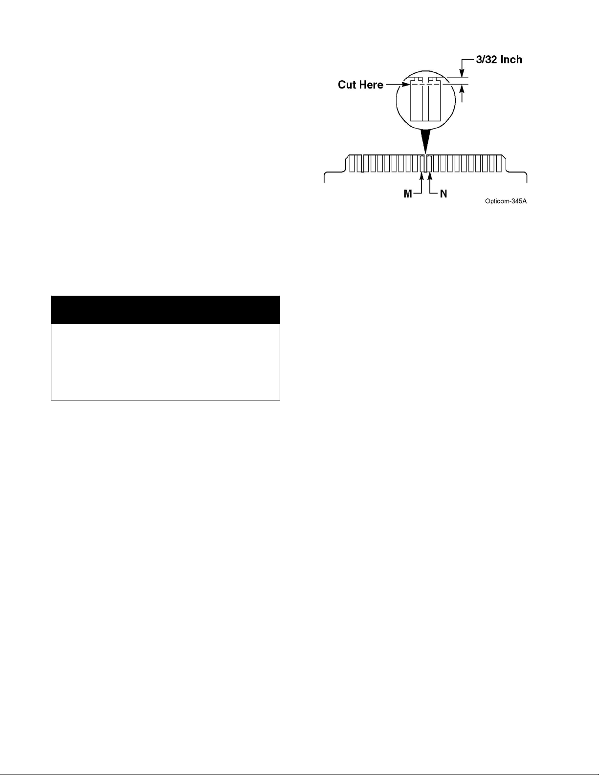
3. Locate pin L on the 44-pin edge
connector of each card rack and verify
continuity to earth ground. See
Figure 1. Set an ohmmeter to its
lowest resistance scale. Measure the
resistance between pin L and earth
ground for each slot in which a phase
selector/discriminator resides. If the
resistance is less than 5 ohms, pin L is
grounded properly.
4. If the resistance is greater than 5 ohms,
inspect the card rack wiring and repair
and/or replace as necessary to correct
the problem, then retest the resistance.

Figure 1 Card rack Continuity Test
Evaluate Device
Use the following procedure to determine
whether the device is a first-generation design or
a second-generation design. A second-generation
device already minimizes the risk of electrical
shock; however, a first-generation device requires
modification to reduce the risk of electrical shock.
1. Place the device, component side down,
on a static-free workstation surface.
2. Compare pins M and N of the card edge
connector. Figure 2 shows a first-
generation device. Figure 3 shows a
second-generation device.
3. If the device is second-generation, the risk
of electrical shock is already minimized.
•Re-install the device in the card rack,
making sure it is fully seated.
•Turn on AC power to the card rack.
4. If the device is first-generation, a shock
potential exists. The device requires
modification to reduce the risk of
electrical shock.
When you insert the device into the card rack,
the modification ensures that the device is
grounded (through pin L) before the power
contacts (pins M and N) are connected. When
you remove the device from the card rack, the
device remains grounded until after the power
contacts are disconnected.
Figure 2 First Generation Device
(Modification Required)
Figure 3 Second Generation Device
(Modification not Required)

Return Device to GTT for Repair
We recommend that you return first-generation
devices to GTT for modification, at no charge.
Please return the device to:
Global Traffic Technologies
Repair Department
7800 Third Street
Building 100
Oakdale , MN 55128-5441
Figure 4. Modify Pins M & N
Modify the Device Yourself
Although we recommend returning first-
generation devices to GTT for modification, you
can modify these devices yourself by performing
the following procedure.
Technical Support
CAUTION
This procedure must be performed in an
Electro-Static Discharge (ESD) free
environment. Failure to perform this
procedure in the proper environment may
damage the equipment.
If you have questions or comments concerning
this technical bulletin, please call the GTT
Technical Service department at: 1-800-258-
4610.
1. Carefully cut pins M and N at 3/32 inch
from the edge of the board, as shown in
Figure 4.
2. Remove the gold material from the edge
of the board back to the cut. When you
are done modifying pins M and N, they
should look similar to the pins shown in
Figure 3 (gold set back 3/32 inch).
3. Record the model number and serial
number, and send them to the Repair
Department.
4. Re-install the modified device in the card
rack, making sure it is fully seated.
5. Turn on AC power to the card rack.

Important Notice to Purchaser:
EXCEPT FOR THE LIMITED WARRANTIES SET FORTH IN THIS DOCUMENT, GLOBAL TRAFFIC
TECHNOLOGIES (GTT) MAKES NO OTHER WARRANTIES AND EXPRESSLY DISCLAIMS ALL OTHER
WARRANTIES, WHETHER EXPRESS OR IMPLIED, INCLUDING, WITHOUT LIMITATION, ANY
WARRANTY AS TO MERCHANTABILITY OR FITNESS FOR A PARTICULAR USE.
GTT will, at its sole option, repair, replace or refund any amounts paid for any OpticomTM Infrared
System component found to be defective in materials or manufacture within five (5) years from the date
of shipment from GTT. See “Warranty and Extended Coverage” for details and limitations of the
coverage plan. GTT will provide a functioning replacement component at a standard charge per unit for
an additional five (5) years.
GTT warrants future system operability coverage as described herein. The warranties set forth in this
document shall not apply to (A) incandescent lamps (confirmation lights) or (B) to any Opticom infrared
system components which have been (1) repaired or modified by persons not authorized by GTT; (2)
subjected to incorrect installation, misuse, neglect or accident; (3) damaged by extreme atmospheric or
weather-related conditions; or (4) subjected to events or use outside the normal or anticipated course.
IN NO EVENT SHALL GTT BE LIABLE FOR ANY INJURY (INCLUDING, WITHOUT LIMITATION,
PERSONAL INJURY), DEATH, LOSS, OR DAMAGE (INCLUDING, WITHOUT LIMITATION, PROPERTY
DAMAGE), WHETHER DIRECT, INDIRECT, INCIDENTAL, SPECIAL, CONSEQUENTIAL, OR
OTHERWISE, ARISING OUT OF THE USE OR INABILITY TO USE, REPAIR OR FAILURE TO REPAIR,
ANY GTT PRODUCT. REGARDLESS OF THE LEGAL THEORY ASSERTED. THE REMEDIES SET FORTH
IN THIS DOCUMENT ARE EXCLUSIVE.
Sale and use of the Opticom infrared system is expressly restricted to authorized agencies of government
customers, within their specific jurisdictions. However, because the infrared signal generated by the
Opticom infrared system is not exclusive, GTT does not warrant exclusive activation by purchaser.
Global Traffic Technologies, LLC Global Traffic Technologies Canada, Inc. Opticom is a trademark of Global
7800 Third Street North 157 Adelaide Street West Traffic Technologies, LLC
St. Paul, Minnesota 55128-5441 Suite 448 Used under license in Canada
1-800-258-4610 Toronto, ON M5H 4E7 Please recycle. Printed in the U.S.A.
651-789-7333 Canada @ Global Traffic Technologies, LLC 2007
www.gtt.com 1-800-258-4610 All rights reserved.
75-0500-3203-8 Rev. B
This manual suits for next models
8
Other Global Traffic Technologies Safety Equipment manuals