Metroplast PRO 2000 User manual

1

2
CONTENTS
1. Security Equipment Selection Criteria ………………………..3
2. Advantages of Usage of PRO 2000…..……………….…….…3
3. Sign Analysis ………………………………………………….3
4. General Rules ……………………………….…………….......4
5. Security Equipment Components …………………..…………5
6. Brake –Rail Position ………………………..………………...5
7. Installation of Security Equipment…………………………….6
8. Regulator Connection …………….……………………..…….7
9. Centralization Mechanism …………………………………….7
10. Important Warnings ………….………………………………8
11. Label Sample …………………………………………….....9
12. Maintenance Details …………………….……………….....9
13. Significant Conditions to Be Paid Attention ………...……..9
14. Transportation and Storage Transportation and Storage ...…10
15. Braking Registry Form………………………………...........11
16. Certificates ……………………………………………...12-13

3
1. —SECURITY EQUIPMENT SELECTION CRITERIA: Rev: 01
During the selection of security guard period, the properties specified below should be known and
stated while ordering. Slip brake operates depending on the pressure applied by the friction shoes onto
the rail surface, friction co-efficient and the strengths of the springs having effect on shoes.
Total of operating load of the security equipment (P + Q),
Weight of cab (P)……………………kg,
While determining the P load, empty cab, load bearing skeleton, parts hanging to the cab, ropes,
balancing ropes, chains, part of the flexible cable which is carried by the cab and other weights must
be taken into consideration.
Carrying capacity (Q)………………..kg,
It is the carrying load of the elevator that is declared.
Operating speed of the cab (V)…………………….m/s,
It is the normal operating speed of the elevator that is declared.
Rail dimensions………………………………………….mm.
Rail form and lubricating type,
Treated →Greasy
Dry
Cold Drawn →Greasy
Dry
2. --- ADVANTAGES OF USAGE OF PRO 2000:
In the event that the declared speed is exceeded, braking upstream and downstream activates
with the movement taken from speed regulator.
It provides easy installation, it does not require complicated processes.
It is tidy in mono block body.
It can be mounted on lower and upper girders of the suspension.
Braking operation occurs in the middle of brake block.
It requires no additional adjustments. It is enough to make the centralization and connection
properly.
It provides easy maintenance.
3 - SIGN ANALYSIS:
It means that ATTENTION should be paid and carries high risks, so the instructions
must be completely performed.
It means that NO ADJUSTMENT is made.

4
4.—GENERAL RULES:
This installation manual has been prepared for realization of connection of the product onto the
suspension in a safe way, and for maintenance of the security equipment.
KEEP THE MANUAL IN A PLACE WHERE ALL STAFF
INTERESTED IN THIS JOB CAN EASILY READ IT.
PRIOR TO MOUNT OPERATION, DO NOT START CONNECTION
PROCESSES BEFORE READING THE WHOLE OF THIS MANUAL.
*Responsibility in terms of the faults to occur during the brake installation is
completely on the company that will perform the mounting operations. Under
no circumstances must any addition or change be made on the brake without
consent of the manufacturer. Spare parts cannot be purchased out of
manufacturing company, and additions and non-original part replacements
cannot be performed.
*Regulator connection of the brake should routinely be checked manually and operation of its
mechanism should be controlled. The elevator should never be operated during the routine manual
control of the brake and necessary security precautions should be taken.
*Exterior painting that can prevent the brake mechanism from operating should be avoided.
* Before the elevator is commenced in buildings which are newly constructed, and where the elevator
is firstly started, any contacts of debris and mortar residuals remaining from construction works with
brake block and tightening mechanism should be prevented. Construction residuals on the rail should
be cleaned, and then it essential that the rail protective oil be completely cleaned. The protective oil
forms a thick and viscous layer. Not completely cleaning the said oil prevents the brake mechanism
from operating at desired values, and it forms a wedge in the rails and avoids the brake stopping in the
wished distances. In the event that such a case occurs, it is essential that the brake blocks be checked,
and that the brake shoes be completely cleaned from foreign matters, oil and residuals. The elevator
should not be operated as long as such controls are made.
The product is delivered to the user after the necessary adjustments have been completed, so the seal
on the purchased product should be checked and the products, seals of which are removed, and those
are damaged during the shipment must not be used.
*Installation operations must be performed by the staff trained about the brake installation and having
information about the brake values, brake direction, connection type and strength values, this rule
must be obeyed in each step of this operation.

5
5. SECURITY EQUIPMENT CONNECTION:
Connection of security equipment blocks can be made onto the heads of lower or upper girders of
suspension. It provides an easy connection through 4 M12 bolts.
Connection bolts should be steel bolts in quality to meet the load in braking. The connection of twins
block in both sides should be provided by the help of a Part that can wholly forward the movement to
the moving shafts of both blocks. It is recommended that the interconnection component be filled
material. The material to be used should completely forward the movement between two brake blocks
and not cause any lose or delay in movement.
6. BRAKE –RAIL POSITION:
It should be enabled that the operating distance between fixed jaw on the brake and the
rail is 1. 5 mm, in order that the brake block can be a regular working ambient with
guiding rail. Steel stripes, thicknesses of which are adjusted should be used for these
measurements. Adjustments that is made by the help of eyes can prevent realization of
a precise work. According to the negations in terms of guiding rails to be used, this
distance can be given a tolerance of +/- 0.1 mm.
Remove one of
these springs

6
7. INSTALLATION OF SECURITY EQUIPMENT
Make sure that the brake is in the correct position during installation process. Loads that the brake will
stop downstream and upstream are different. The tip of the arrow on the brake should be upstream.
The brake has been adjusted in way that it can stop a load of (P + Q) downstream and that of Q/2
upstream. In the event that the direction of the brake is reversely placed, the security equipment cannot
stop the cab in case of a free fall.
The direction of the security equipment must definitely be installed in the correct
direction.
Please see that the pulley inside the block equally contacts to the rail in both sides by moving the
brake handle up and down. The brake handle remains in the middle of the block in the neutral position
of the brake, and inside the block the pulley is in a parallel position to the rail. In the movement of the
brake up and down, the pulley contacts by moving on the rail. Braking process stats following the said
contact. The tasks of the pulleys are to tighten the rail together with brake block fixed jaws and to
perform the braking process through pressure formation of the surfaces of the wheels onto the rail
surface.
It is necessary that the connection of the brake onto the suspension be completely made with the sizes
formerly specified and with M12 steel bolts. Brake blocks in both sides should equally be distant from
the rail and see the rail paddle in equal depths. This adjustment is compulsory in order that both sides
of the brake equally and synchronously activate. This case should be ensured by making suspension
skate adjustments. Otherwise, cases such as activation of one side of the brake blocks in advance or
one side’s holding the paddle occurs. This is an undesired condition in operation of the brakes. Brake
calculations have been made by assuming that both sides synchronously and equally hold.
Thus, distance adjustments should precisely be carried out and definitely
checked again prior to proceeding main operation.
In the event that any impropriety is detected in the tests performed before the elevator is taken into
operation, mounting distance errors than can lead to the said impropriety should be corrected. It should
be PAID ATTENTION that the guiding rails to be used are elevator springs complying with ISO 7465
standards. Friction values of materials used in the security equipment have been determined in
accordance with the properties of cold drawn and treated rails specified in the standard. In addition,
excessive lubricating and dirtiness that can occur on the rails cause these values to change. Thus,
excessive lubricating, dust, dirtiness etc should be prevented from forming on the rails.
No excessive lubricating should be done on the rails. In regular maintenances every month, whether
foreign matters exist inside of the brake block or not should be checked and corrosion formation
should be prevented. Reel seats should be checked in monthly maintenances and inside of the reel
seats should be cleaned during the 6 months or yearly maintenances.
Recovery of the cabin from the brake following the braking action should be performed by a qualified
personnel by moving it in contrary to the direction of the braking.

7
8. REGULATOR CONNECTION
It is necessary that brake handle be in the same direction with the regulator rope in the connection of
brake block onto the suspension. Brake handle can be placed in brake blocks in both sides.
Brake blocks must definitely not be reversed while performing such adjustment.
Upstream should always be fixed. It is necessary that the brakes in both sides
change their places so that this adjustment can be made.
Operation of the brake starts with activation of speed regulator. In the event that the speed of elevator
exceeds the declared speed and reaches the regulator operating speed, the regulator is locked and pulls
the regulator rope. In this case, braking process is realized with the movement of brake handle in both
directions (downstream and upstream), depending on the direction of excessive speeding. The point to
be paid attention most here is the pulling strength of the regulator rope.
Triggering force applied by the regulator to the brake handle with the help of rope should be in
greatness to activate the brake. For this, forces of centralizing springs to be used in brake
mechanism should be taken into consideration. Soft springs cannot hold the brake block in the
center in normal operation as well as excessively hard springs can prevent the brake mechanism
from operating when necessary.
A force of minimum 300 N should be applied to the brake handle through speed regulator rope in
order that the brake can activate (downstream and upstream). For the force equations, apart from the
said one, to be used, drawn force of regulator rope downstream and pulling force of regulator tension
weight upstream should be taken into consideration.
9. Centralization Mechanism
Before taking, please make sure that the speed regulator properly operates and its direction is correct.

8
Main locking direction of the beak of the regulator should be downstream,
however, regulators are bidirectional.
Please make sure that the rope coming from the speed regulator to the brake handle is connected in
way that it does not prevent the movement of the brake handle and loosen. Check whether or not the
drawing direction of the rope is in a way that it realizes the braking upstream in the event that the
speed regulator is locked.
10. IMPORTANT WARNINGS:
Erroneous adjustment or placement in a wrong direction of the brake may result in cabinet fall. In the
event that any change is required in terms of new adjustments, it is essential that those changes be
discussed with the manufacturing company, and be made by an authorized personnel.
Recovery operation following the braking process should be performed by a personnel qualified in this
work. Any risks resulting from changes on products made without the knowledge of manufacturing
company, and from usages out of its objectives are under the responsibility of assembly firm.
It is necessary that the distance between the rail and brake block be 5 mm. The rail should not contact
with brake body.
After each usage, the security guard should be placed after it is made sure that there exists no
deformation in the brake body, reels and any of parts, especially after making sure that there is no
crack-break in pulleys and block.
The security guard should be readjusted after 4 trials and its parts should be
replaced.
Under no circumstances can any addition, extraction or adjustment regarding the
safety guard (brake) be made without the knowledge of the manufacturing
company.
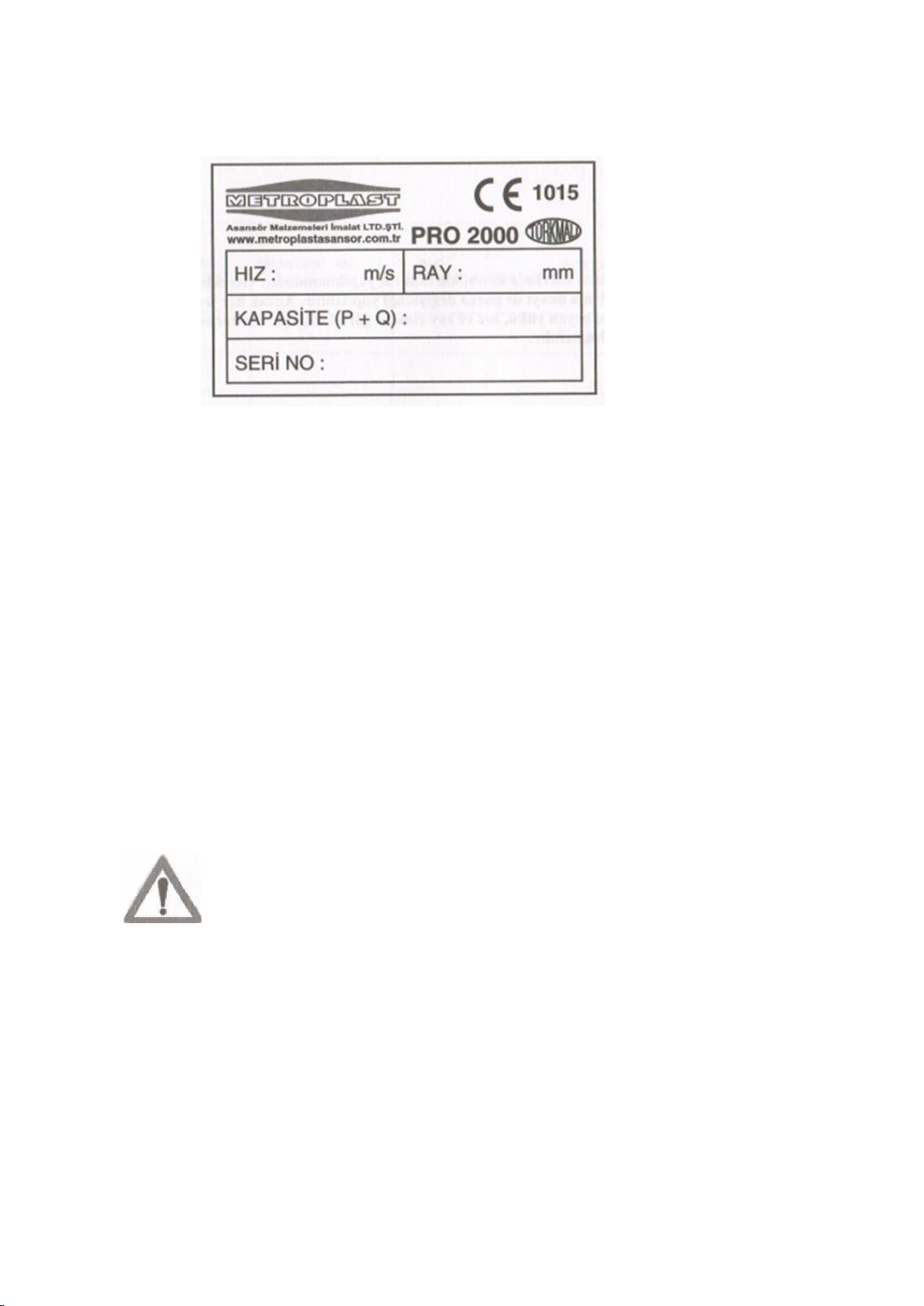
Serial number, capacity, rail thickness, maximum braking speed are specified on the product.
Serial No: Those starting with A represent the cold drawn springs,
Those starting with B represents hot drawn springs.
Rail: It is specified as 9 mm or 16 mm on the cover.
Speed: Maximum braking speed is specified as m/s.
Capacity: Total mass is specified as P + Q in kilogram.
9
11. LABEL SAMPLE
12. MAINTENANCE DETAILS
No excessive lubricating should be done on the rails. In regular maintenances every month, whether
foreign matters exist inside of the brake block or not should be checked and corrosion formation
should be prevented. Reel seats should be checked in monthly maintenances and inside of the reel
seats should be cleaned during the 6 months or yearly maintenances.
Whether or not the brake block mechanism works properly should be checked, and the appropriateness
of regulator rope connection should be controlled in monthly maintenances. Excessive painting that
can possibly prevent the working parts from operating should be avoided, and rail oil and dust that can
accumulate in the blocks should be controlled.
“The security guard should be readjusted after 4 trials and its parts should be replaced.”
Contact of the security equipment is a safety contact. An isolation in the level of IP4X should
continuously be ensured. It should be checked whether or not such contacts that are contacts without
locks are enabled and there exists any opening in their isolation. Whether this contact fulfils its
function or not should be checked in every monthly maintenance starting from the moment when it is
firstly mounted.
Under no circumstances should any repair be made on the security guard. If it
is necessary, parts can be replaced with the approval of manufacturing
company. However, parts of each brake are different depending on cabinet
weight, declared load, speed and rail type. This case should definitely be taken
into consideration.
13. SIGNIFICANT CONDITIONS TO BE PAID ATTENTION
Make sure that installation operation should be performed by trained personnel.
This security equipment has been manufactured in accordance with the safety standards.
Nevertheless, please use protective clothes and material during the installation process.

10
Please take precautions against falling, crashing and any kind of deformation lest the brake
blocks are damaged
Please take the necessary safety precautions during the installation processes in high places.
Wear barrette and safety belt and make sure that the installation place is safe.
14. TRANSPORTATION AND STORAGE
The product is delivered in cardboard boxes.
The product should be stored in places where humidity and dust does not exist.

11
15. BRAKING REGISTRY FORM
“The security guard should be readjusted after 4 trials and its parts should be replaced.”
Order
No
Date
Braking Speed
P + Q
Remarks
1
2
3
4

12

13
Table of contents
Popular Safety Equipment manuals by other brands

Lanex
Lanex PB-20 instruction manual

SKYLOTEC
SKYLOTEC ANCHOR ROPES Instructions for use

Besto
Besto Buoyancy Aid 50N Instructions for use

TEUFELBERGER
TEUFELBERGER NODUS Manufacturer's information and instructions for use

Troy Lee Designs
Troy Lee Designs Tbone Product owners manual

Innova
Innova Xtirpa Instruction and safety manual

bolle SAFETY
bolle SAFETY B810 quick start guide

SHENZHEN FANHAI SANJIANG ELECTRONICS
SHENZHEN FANHAI SANJIANG ELECTRONICS A9060T instruction manual

Hiltron security
Hiltron security POWER8E Installation and use manual

Salewa
Salewa MTN SPIKE user manual

Hatco
Hatco B-950P installation guide

Sitec
Sitec TX MATIC operating manual


