Global Traffic Technologies Opticom 760 User manual

Installation Manual February 2008
Opticom™Infrared System
Model 760 Card Rack

Installation i
Table of Contents
1 About This Manual ................................................................................................................................1
1.1 Purpose of Manual .......................................................................................................................1
1.2 Manual Conventions ....................................................................................................................1
1.3 Manual Organization ...................................................................................................................1
2 Safety Information.................................................................................................................................2
2.1 Intended Use ................................................................................................................................2
2.2 Technical Support ........................................................................................................................2
2.3 Safety Messages and Safety Labels ................................................................................................2
2.3.1 Safety Message Format .......................................................................................................2
2.3.2 Safety Label Format............................................................................................................3
2.4 Safety Message Contained in this Manual .....................................................................................3
2.5 Safety Label Location....................................................................................................................4
2.6 Safety Considerations ...................................................................................................................4
2.6.1 Personal Safety Equipment and Clothing ............................................................................4
2.6.2 Work Zone Traffic Control .................................................................................................4
2.6.3 Electrical Shock..................................................................................................................4
2.7 Disposal of Device .......................................................................................................................4
3 Description ...........................................................................................................................................5
4 Installation ............................................................................................................................................6
5 Maintenance .........................................................................................................................................8

Installation 1
1About This Manual
1.1 Purpose of Manual
This manual provides step-by-step instructions for
installing the Opticom™ Infrared System Model
760 Card Rack. It is intended for use by installers,
maintenance personnel, and others who are
responsible for the installation and maintenance
of the system.
1.2 Manual Conventions
The conventions listed in Table 1-1 help to make
this manual easier to use by presenting a uniform
approach to the descriptions, phrases, and
nomenclature.
1.3
Manual Organization
This manual is divided into five sections.
Section 1. About This Manual
Contains information about the organization and
content of this manual.
Section 2. Safety Information
Contains important information about the safety
messages, safety labels, safety precautions, and
procedures for installation of this device.
Section 3. Description
Briefly describes the Model 760 card rack and its
wiring harness.
Section 4. Installation
Contains step-by-step installation instructions.
Section 5. Maintenance
Contains information and recommendations to
ensure reliable system operation.
Table 1-1. Manual Conventions
Element Convention Example
Acronyms Uppercase VAC
Model Names First or formal reference: initial
caps
Opticom Infrared System Model 760
Card Rack
Subsequent use or informal
reference: Initial caps for Model,
lowercase for remainder
Model 760 card rack, or the card rack

2Installation
2Safety Information
We provide important safety information and
warnings to assist you in understanding and
avoiding potential harm to yourself, and possible
damage to equipment, during the installation of
the Opticom™ Infrared System equipment.
Although we have included many potential
hazards you may encounter during the installation
of this equipment, we cannot predict all of the
possible hazards and this list should not be a
substitute for your judgment and experience.
Please read and observe all safety information
and instructions in this manual before installing
the system equipment. Also, save this
installation manual and keep it near the
equipment.
If you are unsure about any part of this installation
or of the potential hazards discussed, please
contact your supervisor immediately.
2.1 Intended Use
The system is intended to assist authorized
priority vehicles through signalized intersections
by providing temporary right-of-way through
vehicle operator interface to the system and
through the use of common traffic controller
functions.
2.2 Technical Support
If you have questions about the system, its use, or
operation, please contact your dealer or call the
Global Traffic Technologies Technical Service
department at 1-800-258-4610.
2.3 Safety Messages and Safety Labels
We include safety messages and safety labels in
this manual to help you protect your safety and
the safety of others. This section contains
important information to help you recognize
and understand these safety messages.
Please read all messages before proceeding with
the installation.
Safety Message Format
Safety messages are designed to alert you to
potential hazards that can cause personal injury
to you or others. They can also indicate the
possibility of property damage.
Each safety message box contains a safety alert
symbol ( ); one of three signal words:
DANGER, WARNING, or CAUTION; and a safety
message.
The signal words and symbols, and their
meanings, are shown below:
DANGER
The safety message is in this box.
DANGER means you and/or someone else WILL
be KILLED or SERIOUSLY HURT if you do not
follow these instructions.
WARNING
The safety message is in this box.
WARNING means you and/or someone else MAY
be KILLED or SERIOUSLY HURT if you do not
follow these instructions.
CAUTION
The safety message is in this box.
CAUTION means you and/or someone else MAY
be HURT or property damage may result if you
do not follow these instructions.
In addition to the symbols and words explained
above, each safety message identifies the hazard,
describes what you can and should do to avoid
the risk of exposure to the hazard, and tells the
probable consequences of not avoiding the
hazard.
2.3.1

Installation 3
2.3.2 Safety Label Format
We include safety labels on the devices to help
you protect your safety and the safety of others.
Safety labels are designed to alert you to potential
hazards associated with a piece of equipment that
can cause personal injury to you or others. They
can also indicate the possibility of property
damage.
Please read all safety labels.
Each safety label contains a safety alert symbol,
(); one of three signal words: DANGER,
WARNING, or CAUTION; a pictorial showing the
nature of the hazard; and a safety message.
The signal words and symbols, and their
meanings, are shown below:
DANGER means you and/or someone else WILL
be KILLED or SERIOUSLY HURT if you do not
follow these instructions.
WARNING means you and/or someone else MAY
be KILLED or SERIOUSLY HURT if you do not
follow these instructions.
CAUTION means you and/or someone else MAY
be HURT or property damage may result if you
do not follow these instructions.
We consider safety labels to be an important part
of all devices and they should be replaced
immediately if they become hard to read.
If any of the safety labels are missing, or cannot
be read, please contact your dealer or the GTT
repair department for a replacement.
2.4 Safety Message Contained in this
Manual
The following safety message appears in this
manual:
WARNING
This procedure may expose you to AC
voltage and the risk of electric shock or
electrocution. Turn off the AC mains and
use accepted and recognized safety
precautions to avoid exposure to the risk of
electric shock or electrocution. Electric
shock may cause sever injury or death.
2.5 Safety Label Location
There is one safety label on the Opticom™
Infrared System Model 760 Card Rack. If it is
missing or cannot be read, please contact your
dealer or GTT repair department for a
replacement. See Figure 2-1 for the safety label
location.

4Installation
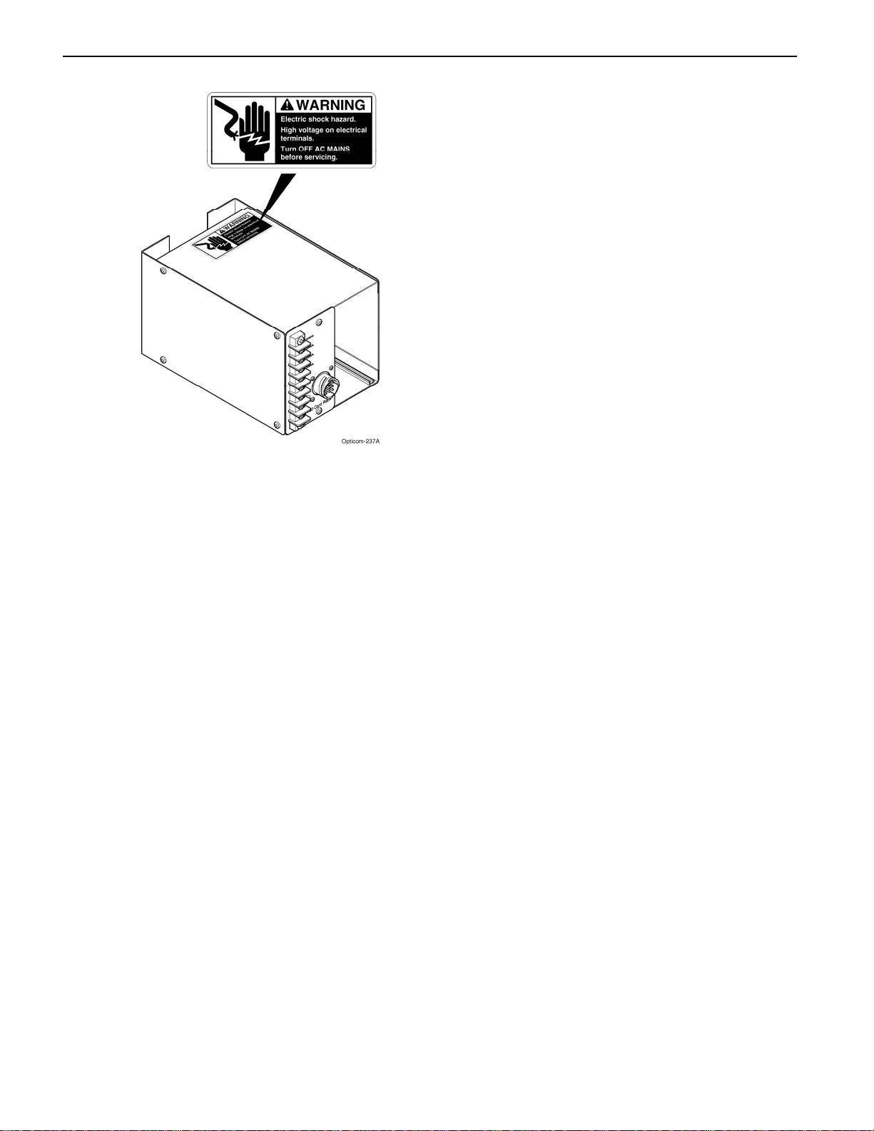
Figure 2-1. Safety Label Location
2.6 Safety Considerations
Please consider the following safety issues before
beginning the installation.
Although we have provided this list of common
safety considerations, it should not be considered
as complete. It is not intended to take the place of
your good judgment, training, and experience.
2.6.1 Personal Safety Equipment and Clothing
Personal safety equipment and clothing including
high visibility vests, hard hats, gloves, electrical
shock or electrocution protection clothing and
equipment, safety shoes, safety glasses, face
shields, goggles, and hearing protection devices
are just some of the items available to you.
Choose the right equipment for the job. If you are
unsure of which safety equipment is
recommended or appropriate for the job, ask your
supervisor or foreman.
Work Zone Traffic Control
Proper control of vehicle traffic is important
during many procedures. When you switch the
traffic controller to and from the flash mode we
recommend that you have people trained in
manual traffic control, such as police officers,
assist you.
When you install devices that require you to
position vehicles, equipment, or people in or near
the roadway; it is important that you use
appropriate work zone traffic control techniques,
equipment, and procedures. Sometimes you may
have to work on or near the roadway and these
same techniques, equipment, and procedures
should be used for your protection.
If you are unsure of which procedures are
recommended or appropriate for the job, ask your
supervisor or foreman.
2.6.3 Electrical Shock
The possibility of electrical shock exists when
installing Opticom system equipment, since
connections must be made to open terminals
within the traffic control cabinet which may have
120 VAC present. Follow proper work
procedures and read and understand the safety
messages in this manual.
As a trained installer of electrical equipment you
are aware of the dangers associated with the
installation of electrical devices. Always be sure
that the power to the equipment, and all
associated equipment, is turned off before
beginning any procedure. Use the equipment,
techniques, and procedures that you learned
during your training or apprenticeship or other
electrical industry recognized safety procedures.
If you are unsure of which techniques,
procedures, and protective equipment are
recommended or appropriate for the job, ask your
supervisor or foreman.
2.6.2
2.7 Disposal of Device
Please dispose of the device in accordance with
all local, state, and federal laws and regulations.

Installation 5
3Description
The Model 760 card rack is usually required in
N.E.M.A.1type controller installations.
The Model 760 card rack is also used when input
file space is not available for Type 1702controller
installations.
Card slot X1 in the Model 760 card rack is
dedicated to Opticom phase selectors and
discriminators. The X1 edge connector is wired
to connector J1 on the card rack front panel. The
card rack is connected to the traffic controller by
a 9-pin wiring harness. The wiring harness
provides inputs and outputs to the traffic
controller system hardware.
NOTE
Illustrations and connections to the traffic
controller may not be exactly as shown or
described in this manual. Refer to the
controller wiring diagram for correct
terminal connections.
1National Electrical Manufacturer’s Association
2California/New York Type 170 Controller Input File

6Installation
4Installation Table 4-1. 9-Pin Harness Wiring
Wire Color Pi
n
Function
Black 1 115 VAC (AC+)
White 2 AC return (AC–)
Green 3 Chassis ground
4 Not used
Gray/White 5 Ch A priority control
output
Blue/White 6 Ch B priority control
output
Violet/White 7 Ch C priority control
output
Brown/White 8 Ch D priority control
output
Gray/Black 9 Logic ground
This section describes the installation of the
Opticom™ Infrared System Model 760 Card
Rack.
WARNING
This procedure may expose you to AC
voltage and the risk of electric shock or
electrocution. Turn off the AC mains and
use accepted and recognized safety
precautions to avoid exposure to the risk of
electric shock or electrocution. Electric
shock may cause sever injury or death.
1. Place the card rack at the desired location in
the controller cabinet.
2. Locate the controller terminals for AC+, AC–,
chassis ground, logic ground, and the priority
control (preemption) inputs.
6. Tape off and cable tie all unused wires.
NOTE
AC power connections should be made
after the circuit breaker, and any surge
protection devices.
7. Connect plug P1 to connector J1 on the
Model 760 card rack front panel.
NOTE
The AC mains will be turned on when the
phase selector or discriminator is installed in
the card rack and the installation procedures
are complete. For information on the phase
selector or discriminator installation, see the
Installation Instructions manual for the
Model 752/754 and 752N/754N phase
selectors, or the Model 452/454 and
252/254 discriminators.
3. Route the 9-pin harness wires to their
terminals.
4. Strip 1/4-inch of insulation from each wire to
be used.
5. Install a spade lug on each wire and connect
it to the appropriate terminal. See Figure 4-1
and Table 4-1.

Installation 7
Figure 4-1. 9-Pin Harness Wiring

8Installation
5Maintenance
Opticom™ Infrared System components are
designed for reliable operation. Inspect the
components at regular intervals to ensure
proper system operation.
GTT recommends the following:
•Each intersection and vehicle system should
be inspected and tested at least every twelve
months to ensure that it functions to your
specifications and requirements.
•Intersection systems should be tested with
known good emitter systems.
•Emitter systems should be tested with known
good intersection systems.
•You should develop a test plan that fits your
department’s operations and meets the needs
of your system.
•You should keep accurate and up-to-date
records of system performance and test
results.

Important Notice to Purchaser:
EXCEPT FOR THE LIMITED WARRANTIES SET FORTH IN THIS DOCUMENT, GLOBAL TRAFFIC
TECHNOLOGIES (GTT) MAKES NO OTHER WARRANTIES AND EXPRESSLY DISCLAIMS ALL OTHER
WARRANTIES, WHETHER EXPRESS OR IMPLIED, INCLUDING, WITHOUT LIMITATION, ANY
WARRANTY AS TO MERCHANTABILITY OR FITNESS FOR A PARTICULAR USE.
GTT will, at its sole option, repair, replace or refund any amounts paid for any OpticomTM Infrared System
component found to be defective in materials or manufacture within five (5) years from the date of shipment
from GTT. See “Warranty and Extended Coverage” for details and limitations of the coverage plan. GTT will
provide a functioning replacement component at a standard charge per unit for an additional five (5) years.
GTT warrants future system operability coverage as described herein. The warranties set forth in this
document shall not apply to (A) incandescent lamps (confirmation lights) or (B) to any Opticom infrared
system components which have been (1) repaired or modified by persons not authorized by GTT; (2)
subjected to incorrect installation, misuse, neglect or accident; (3) damaged by extreme atmospheric or
weather-related conditions; or (4) subjected to events or use outside the normal or anticipated course.
IN NO EVENT SHALL GTT BE LIABLE FOR ANY INJURY (INCLUDING, WITHOUT LIMITATION,
PERSONAL INJURY), DEATH, LOSS, OR DAMAGE (INCLUDING, WITHOUT LIMITATION, PROPERTY
DAMAGE), WHETHER DIRECT, INDIRECT, INCIDENTAL, SPECIAL, CONSEQUENTIAL, OR OTHERWISE,
ARISING OUT OF THE USE OR INABILITY TO USE, REPAIR OR FAILURE TO REPAIR, ANY GTT
PRODUCT. REGARDLESS OF THE LEGAL THEORY ASSERTED. THE REMEDIES SET FORTH IN THIS
DOCUMENT ARE EXCLUSIVE.
Sale and use of the Opticom infrared system is expressly restricted to authorized agencies of government
customers, within their specific jurisdictions. However, because the infrared signal generated by the
Opticom infrared system is not exclusive, GTT does not warrant exclusive activation by purchaser.
Global Traffic Technologies, LLC Global Traffic Technologies Canada, Inc. Opticom is a trademark of Global
7800 Third Street North 157 Adelaide Street West Traffic Technologies, LLC
St. Paul, Minnesota 55128-5441 Suite 448 Used under license in Canada
1-800-258-4610 Toronto, ON M5H 4E7 Please recycle. Printed in the U.S.A.
651-789-7333 Canada @ Global Traffic Technologies, LLC 2007
www.gtt.com 1-800-258-4610 All rights reserved.
75-0500-2278-1 Rev D
Table of contents
Other Global Traffic Technologies Safety Equipment manuals