Simpson Hybrid Pro User manual

Installation Manual
The products and parts shown herein are to be installed and used adjusted in accordance with these
instructions. Any deviation by the buyer, installer, or user from these instructions constitutes willful neg-
ligence. Products and parts are not to be used if defective, damaged or worn. Products and parts are
not to be used after a severe use, in any event.
Version 6-09
2
Attaching the Helmet D-Ring
The Hybrid Head and Neck Restraint comes with all of the parts to attach the D-rings to the helmet.
Supplied are: (2) 10-32 ½” screws (2) Nut-Washers and (2) D-rings.
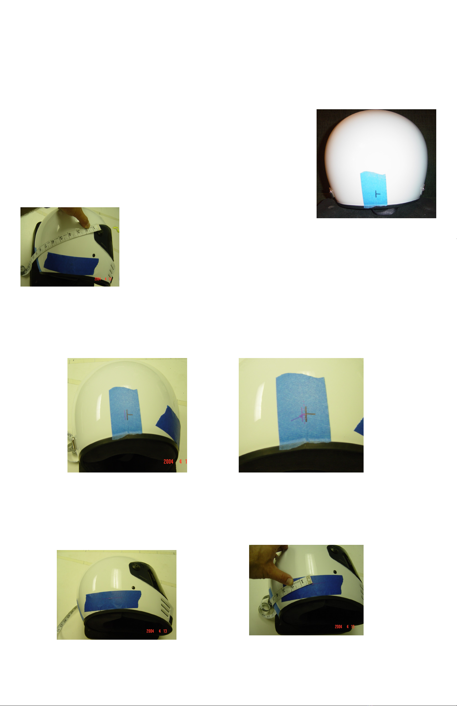
To locate the D-rings:
Find the center of the helmet by:
1) Place a piece of masking tape at the center of the rear of the helmet.
(estimate).
2) Mark the center of the tape 1.5” above the bottom of the helmet and
measure from the helmet visor screw to the marked centerline on the
right side of the helmet.
3) Mark the left side of the helmet by using the measurement found in
step 2 for the right side. Measure from the left side visor pivot point
to the mark in the rear of the helmet. At the same distance as on the
right side, mark on the tape on the rear of the helmet vertically, 1.5”
above the bottom ridge of the helmet.
4)You should have two marks on the tape on the back of the helmet. Measure the distance between
the two marks. The center of the two measurements is the center of the helmet.
5) Measure from the new centerline around the helmet 5.5” (+.5”/-0.0”). Mark this spot 1.5” (+.25”/-
0.0”) above the bottom of the helmet. Repeat the procedure on the opposite side of the helmet.
3
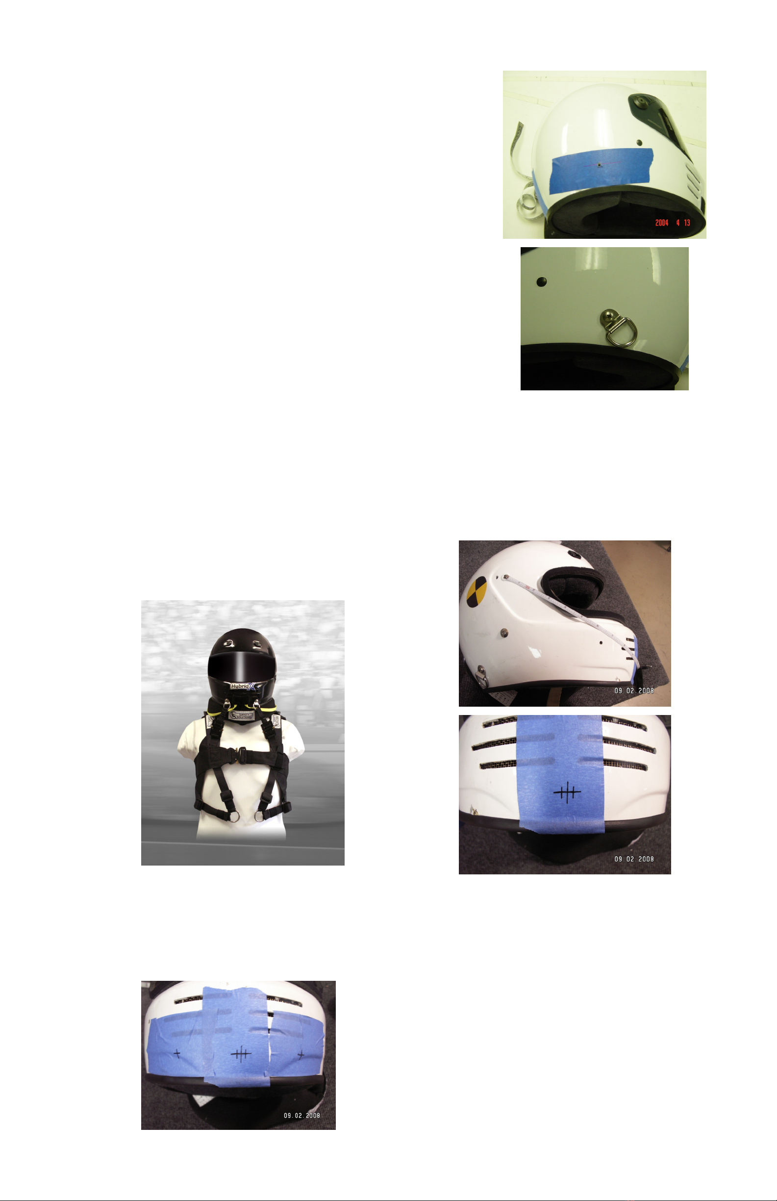
6) Drill the helmet using a 3/16” drill at the point marked in step 5.
7) Clean the hole in the helmet as much as possible.
Put a medium strength locker on the Nut-Washer and place it
on the inside of the helmet over the hole.
Thread the screw from the outside of the helmet trough the D-
ring and into the helmet and Nut-Washer. Tighten the helmet D-
ring screw snuggly. Over tightening is not necessary and could
damage the helmet shell.
Hybrid X Front Tether Installation & Adjustment
This is only used in the “X” Version of the Hybrid
1) Use the mounting hole location of the
visor to find the center of the helmet 1”
up from the bottom of the helmet.
2) Next, measure & mark 2” over from the center of the helmet 1” up and
drill the helmet with a 3/16” bit. (Measurement may have to be adjusted
3/4” up for some helmets).
4
3) Gently pull the foam chin bar loose from the helmet to install the nutwashers for the D-Rings. In-
stall the D-Rings with blue Loc-Tite in each hole.
4) Re-glue the front chin bar with a soft adhesive (silicone, hot glue).

5
The shoulder belts should be mounted as close to the occupant as possible, separated by 2-3 inches
at the mount.
The correct restraint model, (I.E. 10 degree, 15 degree…..) is chosen by the seat angle and contour.
The restraint should “fit” the contour of the seat and head rest / head restraint. The driver can
quickly determine if the restraint will fit into the car’s seat by holding it against the back of the seat
lined up with the shoulder belts.
If the restraint contacts the headrest at the top and bottom only, a different model may be chosen or
the headrest can be set back to allow room for the restraint.
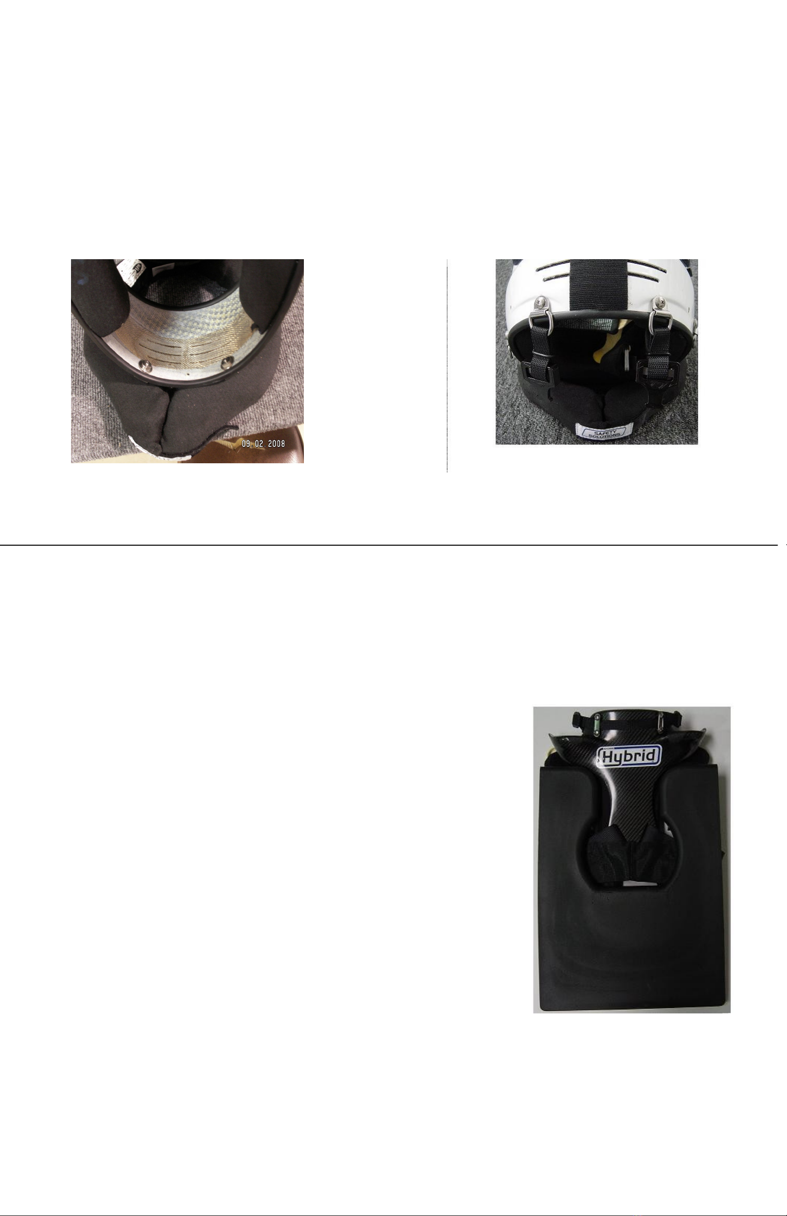
Fitting the Restraint to the Wearer
The Hybrid Head and Neck Restraint has an adjustable chest strap to fit a variety of wearers.
To adjust the chest strap: loosen the chest strap in the buckle and slide the buckle to fit the occu-
pant’s chest size. Since the chest strap provides a load path for head load, the harness should fit
snug to tight in the chest area.
6
Helmet Tether / In Car Adjustment
Waist Strap Adjustment and Fitting
The waist strap needs to attach to the seat belt buckle. It is a load path for the restraint, stabi-
lizing the carbon part on the back of the wearer. There are different attachment methods and ends
to connect into a variety of different racing harnesses. The photo below shows a latch and link
buckle system.
To adjust the waist strap the wearer must be seated in the car. The loops can connect into any
part of the seat belt buckle that allows the loops to fall off the buckle when the buckle is released.
There are systems that lend themselves to having the loops on the shoulder belt links, lap belt
links, or the tongue of a latch and link system. A variety of links and loops can be ordered from
Simpson, or your dealer.
The waist straps should be adjusted to be snug when the buckle is latched. You should be able to
fit at least 2 fingers under the belt when the buckle is latched. Adjustment is made by sliding the
1” Webbing attaching the loops through the 3 bar adjuster on the waist strap.
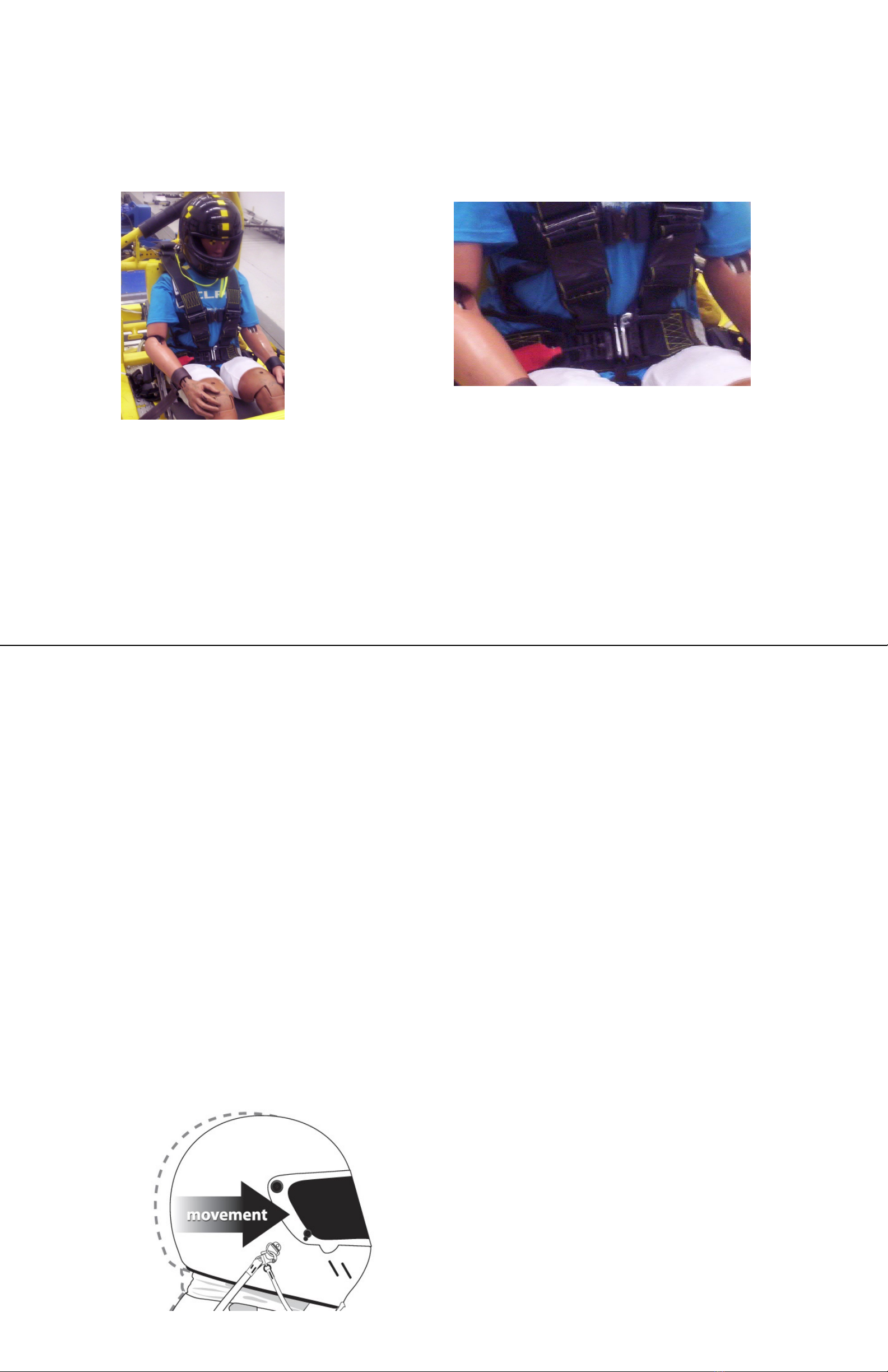
The Helmet Tethers need to be adjusted with the driver seated and buckled into the vehicle.
Restraint Tethers:
1) Get into car and buckle into the seat.
2) Once seated in the car, position the restraint comfortably under the shoulder harnesses and be-
tween the foam pads inserted in the seat.
3) With the helmet strapped securely, pull the yellow Quick Release tethers to open the Quick Re-
lease on the restraint.
4) Attach the Quick Release to the Helmet Hook on the helmet making sure to have the tether ring
pointing down.
Note: The Quick Release will release better if the bail is hooked to the helmet D-ring from the “outside in”.
The helmet tethers are adjusted by weaving the tether through the 3-bar adjuster attached to the re-
straint. Make sure to lock the webbing when the adjustment is made by weaving the tether back
through.
5) With help, adjust the Helmet Tether to allow 1” (+1.25”/ - 1.0”) of straight forward movement before
restraint is felt. (Early restraint has been seen to reduce the overall neck tension in an impact with
a Hybrid Head and Neck Restraint.) This should allow up to 45 degrees of side to side rotation.

7
Quick Release
Tether Placement
The Quick Release Tethers
should be Velcro’d to the chin
bar of the helmet.
NEVER attach the tethers
to the seat belts or the car.
Side Stabilizing Gusset Adjustment
1) With the driver still properly seated in the
seat, and after adjusting the forward tethers
with the side gussets unhooked, hold the side
gusset up to the D-Ring (see picture 1).
2) With the D Ring angled down at a 45 de-
gree angle, check to see that the side gusset
is 0-3/4” below the bottom of the wire loop,
and adjust the strap accordingly to meet
these guidelines (see picture 2).
3) Now slide the Quick Release tether
through the side gusset and onto the Quick
Release (see picture 3).
Picture 1
Picture 2
Picture 3
WARNING: This article is sold without warranty, expressed or implied. No warranty or representation
made as to this products ability to protect the user from any injury or death. The user assumes that risk.
This manual suits for next models
2
Table of contents
Popular Safety Equipment manuals by other brands


Guardian Fall Protection
Guardian Fall Protection Angel Anchor instruction manual

LAHTI PRO
LAHTI PRO L30423 user manual

Guardian
Guardian Non-Shock Lanyard instruction manual

ASO Safety Solutions
ASO Safety Solutions Sentir Safety Contact Bumper instruction manual

Haws
Haws 8140 Installation, operating, & maintenance instructions

Spencer
Spencer FA user manual


