Global Traffic Technologies Opticom 792R User manual

Installation Manual June 2010
Opticom™Infrared System
Model 792R Emitter


Installation i
Table of Contents
1 About This Manual ................................................................................................................................1
1.1 Purpose of Manual .......................................................................................................................1
1.2 Manual Conventions ....................................................................................................................1
1.3 Manual Organization ...................................................................................................................1
2 Safety Information.................................................................................................................................2
2.1 Intended Use ................................................................................................................................2
2.2 Technical Support ........................................................................................................................2
2.3 Safety Messages and Safety Labels ................................................................................................2
2.3.1 Safety Message Format .......................................................................................................2
2.3.2 Safety Label Format ............................................................................................................3
2.4 Safety Messages Contained in this Manual....................................................................................4
2.5 Safety Label Locations ..................................................................................................................5
2.6 Safety Considerations ...................................................................................................................6
2.6.1 Personal Safety Equipment and Clothing ............................................................................6
2.6.2 Electric Shock.....................................................................................................................6
2.6.3 Explosion ...........................................................................................................................6
2.6.4 Chemical Burns..................................................................................................................6
2.7 Disposal of Device .......................................................................................................................6
3 Description ...........................................................................................................................................7
3.1 Opticom System ...........................................................................................................................7
3.2 Model 792R Emitter......................................................................................................................7
4 Features.................................................................................................................................................9
5 Installation ..........................................................................................................................................10
5.1 Emitter Installation......................................................................................................................11
5.2 Emitter Control Switch Installation..............................................................................................14
5.3 Final Wiring Connections ...........................................................................................................17
5.3.1 Power Connection Recommendations..............................................................................18
5.3.2 Power Connection Testing................................................................................................18
5.4 Emitter Cable Connector Pin Index .............................................................................................19
5.5 Setting Disable Mode and Vehicle ID Code................................................................................19
6 Checkout.............................................................................................................................................21
6.1 Installation Checkout..................................................................................................................21
6.2 Performance Tests ......................................................................................................................21
7 Range Setting (Automated Signal Intensity Threshold Level Adjustment) ............................................22
8 Maintenance .......................................................................................................................................23
9 Troubleshooting ..................................................................................................................................24

ii Installation

Installation 1
1About This Manual
1.1 Purpose of Manual
This manual provides step-by-step instructions
for installing OpticomInfrared System Model
792R Emitters*. It is intended for use by
installers, maintenance personnel, and others
who are responsible for the installation and
maintenance of the system.
1.2 Manual Conventions
The conventions listed in Table 1-1 help to
make this manual easier to use by presenting a
uniform approach to the descriptions, phrases,
and nomenclature.
1.3 Manual Organization
This manual is divided into eight sections.
Section 1. About This Manual
Contains information about the organization and
content of this manual.
Section 2. Safety Information
Contains important information about the safety
messages, safety labels, safety precautions, and
procedures for installation of this device.
Section 3. Description
Briefly describes the Model 792R emitter and its
related Opticom system components.
Section 4. Features
Describes important features and characteristics
of the Model 792R emitter.
Section 5. Installation
Contains step-by-step installation instructions.
Section 6. Checkout
Contains information on how to check out and
test the installed system.
Section 7. Range Setting (Automated Signal
Intensity Threshold Level Adjustment)
Contains information about adjusting the Signal
Intensity Threshold Level.
Section 8. Maintenance
Contains information and recommendations to
ensure reliable system operation.
Table 1-1. Manual Conventions
Element Convention Example
Model names First or formal reference: initial
caps
OpticomInfrared System Model 792R
Emitter
Subsequent use or informal
reference: Initial caps for Model,
lowercase for remainder
Model 792R emitter, or the emitter
Feature names Initial caps the Disable feature
Switch position Uppercase the OFF position
*The method of using the components of the OpticomInfrared system may be covered by US Patent
Number 5172113.

2Installation
2Safety Information
We provide important safety information and
warnings to assist you in understanding and
avoiding potential harm to yourself, and
possible damage to equipment, during the
installation of OpticomInfrared System
equipment. Although we have included many
potential hazards you may encounter during the
installation of this equipment, we cannot predict
all of the possible hazards and this list should
not be a substitute for your judgment and
experience.
Please read and observe all safety information
and instructions in this manual before installing
the equipment. Also, save this installation
manual and keep it near the equipment.
If you are unsure about any part of this installation
or of the potential hazards discussed, please
contact your supervisor immediately.
2.1 Intended Use
The system is intended to assist authorized
priority vehicles through signalized intersections
by providing temporary right-of-way through
vehicle operator interface to the system and
through the use of common traffic controller
functions.
2.2 Technical Support
If you have questions about the system, its use, or
operation, please contact your dealer or call the
Global Traffic Technologies Technical Service
department at 1-800-258-4610.
2.3 Safety Messages and Safety Labels
We include safety messages and safety labels in
this manual to help you protect your safety and
the safety of others. This section contains
important information to help you recognize and
understand these safety messages.
Please read all messages before proceeding with
the installation.
2.3.1 Safety Message Format
Safety messages are designed to alert you to
potential hazards that can cause personal injury
to you or others. They can also indicate the
possibility of property damage.
Each safety message box contains a safety alert
symbol ( ); one of three signal words:
DANGER, WARNING, or CAUTION; and a safety
message.
The signal words and symbols, and their
meanings, are shown below:
DANGER
The safety message is in this box.
DANGER means you and/or someone else WILL
be KILLED or SERIOUSLY HURT if you do not
follow these instructions.
WARNING
The safety message is in this box.
WARNING means you and/or someone else
MAY be KILLED or SERIOUSLY HURT if you do
not follow these instructions.
CAUTION
The safety message is in this box.
CAUTION means you and/or someone else MAY
be HURT or property damage may result if you
do not follow these instructions.
In addition to the symbols and words explained
above, each safety message identifies the hazard,
describes what you can and should do to avoid
the risk of exposure to the hazard, and tells the
probable consequences of not avoiding the
hazard.

Installation 3
2.4 Safety Messages Contained in this
Manual
The following safety messages appear in this
manual:
WARNING
Vehicle batteries contain sulfuric acid and
may contain explosive gases. Keep sparks,
flames, and cigarettes away. Wear eye
protection. Disconnect the negative cable
first to prevent shorting the positive terminal
to the chassis when removing the positive
cable. Battery acid may cause skin irritation
and eye injury. Explosive gases may cause
severe injury or death.
WARNING
Emitter power supplies are high-voltage
devices and carry potentially lethal voltage.
To avoid exposure to high voltage and the
risk of electric shock, disconnect the vehicle
battery and wait 5 minutes after turning off
power before starting work on the emitter.
Electric shock may cause severe injury or
death.
CAUTION
Mount the emitter right side up. Failure to
properly install the emitter may damage the
unit and void the warranty. The GTT Logo on
the lens of the emitter must be right side up and
the two small weep holes must be facing down.
If the weep holes are facing up, the emitter may
fill with water and cause it to fail.
CAUTION
Connecting power to a power distribution
system may not offer the current capacity or
protection of direct connection to the battery,
which may result in damage to the equipment or
vehicle. To avoid this problem, make the
power connection directly to the battery or as
close to the battery as possible. An improper
power connection may result in damage to the
equipment or vehicle.
WARNING
Directly viewing the flash-tube during operation
will expose you to ultraviolet energy and the risk
of personal injury. To avoid exposure to
ultraviolet energy, do not directly view the
flash-tube during operation. View only from the
side and observe reflected light only. Viewing
the flash-tube during operation may cause eye
injury.
WARNING
A completed installation that is not tested may
result in improper system operation, which may
result in accidents and/or injuries. To avoid this
problem, test the system to verify proper
operation. Improper system operation may
result in unsafe driver action.
WARNING
Using the wrong range and timing chart may
cause improper system operation, which may
result in accidents and/or injuries. To avoid the
risk of accidents and/or injuries that may result
from improper system operation, use the range
and timing chart that corresponds to the model
of detector that is being adjusted. Improper
system operation may result in unsafe driver
action.
WARNING
Using a clear lens emitter to set ranges may
cause improper system operation, which may
result in accidents and/or injuries. To avoid the
risk of accidents and/or injuries that may result
from improper system operation, use a visible-
light filtered emitter to set ranges. Improper
system operation may result in unsafe driver
action.

4Installation
2.5 Safety Label Locations
There are two safety labels on OpticomInfrared
System Model 792R Emitters. If a safety label is
missing or cannot be read, please contact your
dealer or the GTT repair department for a
replacement. See Figures 2-1 and 2-2 for the safety
label locations.
Figure 2-1. Emitter Safety Label Location
Figure 2-2. Emitter Fuse Safety Label Location

Installation 5
2.6 Safety Considerations
Please consider the following safety issues before
beginning the installation.
Although we have compiled this list of common
safety considerations, it should not be considered
as complete. It is not intended to take the place of
your good judgment, training, and experience.
2.6.1 Personal Safety Equipment and Clothing
Personal safety equipment and clothing including
high visibility vests, hard hats, gloves, electrical
shock or electrocution protection clothing and
equipment, safety shoes, safety glasses, face
shields, goggles, and hearing protection devices
are just some of the items available to you.
Choose the right equipment for the job. If you are
unsure of which safety equipment is
recommended or appropriate for the job, ask your
supervisor or foreman.
2.6.2 Electric Shock
As a trained installer of electrical equipment you
are aware of the dangers associated with
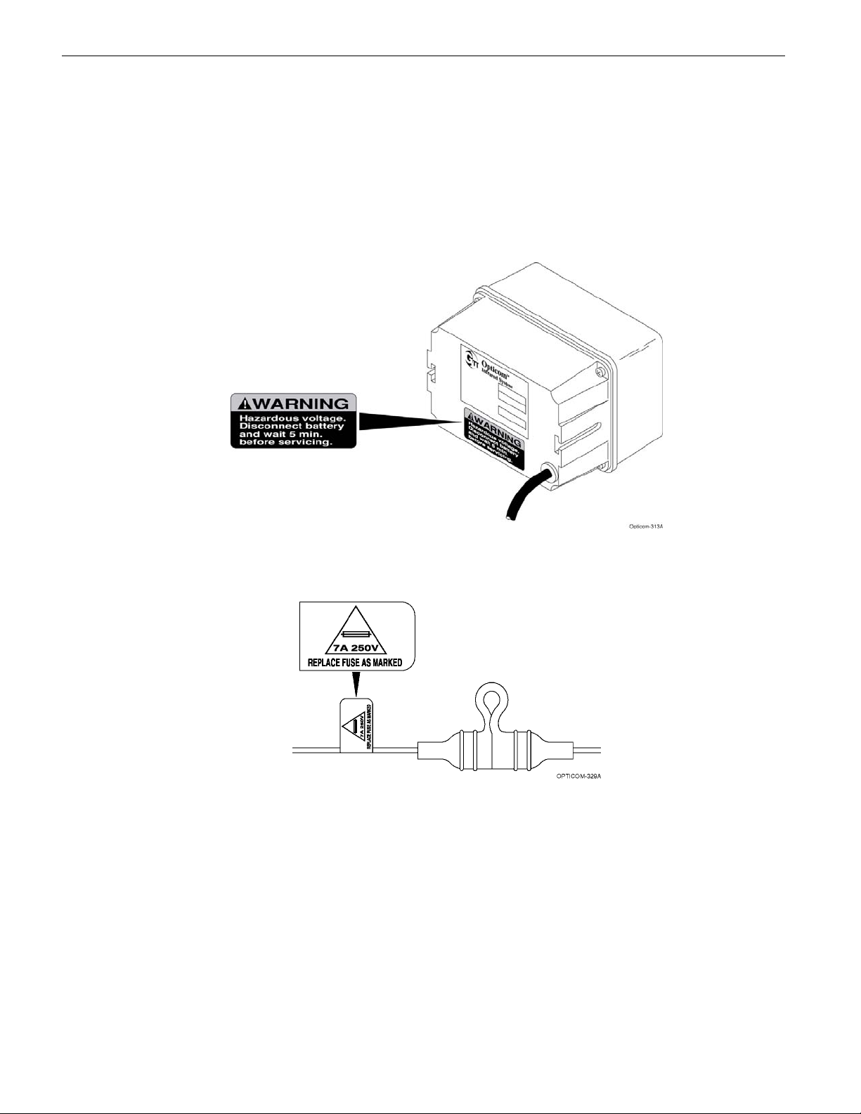
installation of electrical devices. Always be sure
that the power to the equipment, and all
associated equipment, is turned off and the
vehicle battery is disconnected. We also
recommend that you wait for the period of time
specified in the warning message before
beginning any procedure. This waiting period is
required to allow electrically charged
components to discharge and minimize your
exposure to the risk of electric shock and
electrocution. Use the equipment, techniques,
and procedures that you learned during your
training or apprenticeship or other electrical
industry recognized safety procedures.
If you are unsure of which techniques,
procedures, and protective equipment are
recommended or appropriate for the job, ask your
supervisor or foreman.
2.6.3 Explosion
Common automotive-type batteries produce an
explosive gas under some conditions. This gas
may easily be ignited by a spark or flame as you
work on the vehicle. To reduce the risk of
explosion, disconnect the battery, work in a well
ventilated area, avoid the use of devices that
create sparks or use open flames, and use the
appropriate personal safety equipment and
clothing.
If you are unsure of which techniques,
procedures, and protective equipment are
recommended or appropriate for the job, ask your
supervisor or foreman.
2.6.4 Chemical Burns
Common automotive-type batteries contain strong
acid that can cause personal injury if you come in
contact with the acid. To reduce exposure to the
risk of chemical burns wear appropriate
protective clothing and handle the battery with
care.
If you are unsure of which techniques,
procedures, and protective equipment are
recommended or appropriate for the job, ask your
supervisor or foreman.
2.7 Disposal of Device
Please dispose of the device in accordance with
all local, state, and federal laws and regulations.

6Installation

Installation 7
3Description
This section provides a general description of the
Opticom™Infrared System and a detailed
description of Model 792R Emitters.
3.1 Opticom System
The system assists authorized priority
vehicles through signalized intersections by
providing temporary right-of-way through
the use of common traffic controller
functions. The Probe mode records and
communicates information (for example,
vehicle location, travel direction, user class
and identification) which can be used to
provide traffic flow information by
calculating the rate of movement of
designated probe vehicles.
The Opticom system consists of the following
matched components:
•Emitter — Model 792 Emitter.
•Detector — Model 711, 721, and 722
Detectors and Model 138 Detector Cable.
Also auxiliary interface panels, if auxiliary
detectors are used.
•Phase Selector — Model 752 and 754 Phase
Selectors.
•Card Rack/Input File — Model 760 Card
Rack or California/New York Type 170
Controller Input File.
The emitter, with an appropriate emitter control
switch, is mounted on the priority vehicle. It
generates a series of pulses in the infrared and
visible wavelengths. These pulses are sensed by
the detector mounted at the intersection.
The detector converts the infrared energy into
electrical signals that are transmitted by the
detector cable to the phase selector in the traffic
controller cabinet.
For Priority Control mode, the phase selector
discriminates between valid emitter signals and
other sources of energy received by the detectors,
and activates its outputs in response to valid
priority emitter signals. The phase selector
outputs are connected to the traffic controller’s
inputs, to request the traffic controller to deliver
the desired green for the priority vehicle.
For Probe mode, the phase selector logs the user
class, identification, and time, but does not send
any signals to the traffic controller.
Interface cards are required in applications where
the controller cannot recognize external priority
control signals. Interface cards are electrically
connected between the phase selector and the
traffic controller.
The card rack/input file provides the power and
logic wiring for the phase selector, which plugs
directly into a slot in the unit.
3.2 Model 792R Emitter
The Model 792R emitter is a compact, weather-
resistant, infrared energy-emitting device with
optional encoded-signal operation. This emitter is
intended for use on maintenance vehicles. The
emitter system consists of a flash-tube/reflector
module with a built-in power supply, an emitter
cable, and a Model 793R emitter control switch.
The Model 792R emitter converts 12 Volt DC
vehicle battery voltage to the high voltage
required to operate the xenon flash-tube. Using
the Model 793R emitter control switch, the user
can select High Priority, Low Priority, or Probe
mode.
Appropriate vehicle Class and ID numbers are
determined at the time of installation and are
programmed by the user via Model 790-CS
configuration software.

8 Installation
The Opticom™Infrared System Model 792R
Emitter connects to the Model 793R Emitter
Control Switch, which is a custom-designed,
fully-enclosed switch assembly that mounts in the
vehicle operator’s compartment. A mounting
bracket is included. The emitter control switch
has the following three switches:
•On/off switch, this is an alternate-action
switch with a positive latch down in the ON
position, and an indicator light.
•Range switch, which is a momentary-action
range-setting switch. The range switch is used
to implement the Automated Signal Intensity
Threshold Level adjustment.
•Probe/high/low switch, which is a three-
position rocker switch. The upper switch
position (P) selects the Probe mode (emitter
flashes at 12 Hz). In Probe mode, the
controller simply records the passage of the
vehicle through the intersection. Probe mode
does not cause the controller to go into the
Priority Control mode of operation. The
middle switch position (H) selects the High
Priority mode (emitter flashes at 14 Hz). The
lower switch position (L) selects the Low
Priority mode (emitter flashes at 10 Hz).
When the optional Disable feature is installed, it
typically uses an additional switch (customer
supplied) that connects to battery negative when
the switch is activated.
This manual describes how to install the Model
792R emitter, the Model 793R emitter control
switch, and the optional disable switch.
Figure 3-1 shows a typical emitter installation for
a maintenance vehicle.
Figure 3-1. Typical Emitter Installation for Maintenance Vehicle

Installation 9
4Features
Model 792R emitters have the following features:
•Mounts in many lightbars
•Integrated power supply and flash head for
small size
•Impact resistant design
•Operates on 10-16 VDC
•Draws approximately 4.5 Amps
•User-selectable flash rates when used with the
Model 793R emitter control switch module:
High Priority = 14 Hz
Low Priority = 10 Hz
Probe frequency = 12 Hz
•User-adjustable priority signal intensity
threshold level with the Model 793R emitter
control switch
•Vehicle identification encoding; selectable at
installation
•User-selectable disable mode; Latching
or Non-Latching modes
•Disable circuitry (indicator flashes at 0.5 Hz)
•Self-diagnostic capability (indicator flashes at 2
Hz)
•10,000 vehicle identification codes
•Wide operational temperature range:
–30°F to +140°F
•Meets FCC part 15 subpart J Class A
specifications
•CE certified
•SAE J575 JUN92 compliant
•25-foot emitter cable for installation flexibility
•J1708 compliant communication port
•Available Windows™1Configuration and
Maintenance Software
1Windows is a trademark of Microsoft Corporation.

10 Installation
5Installation
This section describes the installation of
Opticom™Infrared System Model 792R Emitters
and Model 793R Emitter Control Switches. It also
describes how to set the Disable mode and the
Vehicle ID code using Model 790-CS
configuration software.
Notes:
Please read and fully understand the following
precautionary paragraphs before starting the
installation.
•Before cutting or drilling any openings in the
vehicle or lightbar, draw a diagram showing
placement, measurements, and dimensions.
Use the diagram to avoid drilling or cutting
holes in undesirable locations.
•Always follow the vehicle manufacturer's
recommendations concerning modification,
alteration, and installation or connection of
accessories or equipment to the vehicle and
lightbar.
•Installation on specialty vehicles (such as
motorcycles, parking enforcement, utility and
special maintenance vehicles) requires
particular care and attention to details.
•Do not mount the emitter within 18 inches of
a radio antenna.
•Follow the installation instructions to avoid
possible radio frequency interference
problems.
•The emitter should point straight ahead, and
should be mounted level (parallel with the
road) and as high on the vehicle as possible.
•The emitter must not be obstructed by other
lights, speakers, grill work, antennas, or other
devices.
•The emitter should not be mounted inside the
passenger compartment.
•Do not operate an emitter with a damaged
lens or place colored lenses in front of the
emitter. Use only a GTT replacement lens.
•Do not operate the emitter unless it is fully
assembled.
•An emitter mounted on the roof should be
positioned at least 12 inches back from the
vehicle windshield to prevent illumination of
the windshield during operation.
•Wires that are routed under carpets or mats
should be run between the pad and the
carpet. This will minimize abrasion and heat
damage from catalytic converters.
•Protect cables with armor or sheathing when
they are routed around sharp corners and
edges. Avoid routing cables through
potential pinch points. Clamp or tie all
cables in place. Route and secure cables well
away from moving parts.

Installation 11
5.1 Emitter Installation
This subsection describes how to install Model
792R emitters.
WARNING
Vehicle batteries contain sulfuric acid and
may contain explosive gases. Keep sparks,
flames, and cigarettes away. Wear eye
protection. Disconnect the negative cable
first to prevent shorting the positive
terminal to the chassis when removing the
positive cable. Battery acid may cause skin
irritation and eye injury. Explosive gases
may cause severe injury or death.
1. Disconnect the battery before beginning the
installation. Disconnect the negative battery
cable first, then the positive battery cable.
2. Remove interior panels and headliners, as
necessary, to provide access for cable routing.
WARNING
Emitter power supplies are high-voltage
devices and carry potentially lethal voltage.
To avoid exposure to high voltage and the
risk of electric shock, disconnect the vehicle
battery and wait 5 minutes after turning off
power before starting work on the emitter.
Electric shock may cause severe injury or
death.
3. Using the emitter bracket as a template, mark
where you want to drill holes at the mounting
location. Be sure the emitter bracket is
parallel with the front of the vehicle.
4. Drill two 1/4-inch holes at the mounting
location.
Note:
•The installer may have to fabricate
special brackets to mount the emitter in
some lightbars.
5. Position the emitter bracket and gasket over
the mounting holes and use two hex head
bolts, flat washers, fender washers, lock
washers, and nuts to secure the bracket to
the vehicle. See Figure 5-1.
6. Check for proper forward alignment, then
tighten the nuts.
Figure 5-1. Emitter Bracket Installation

12 Installation
7. Slide a carriage bolt into the slot on each side
of the Opticom™Infrared System Model 792R
Emitter. Next, slide the two plastic friction
plates onto the bolts with the ridged surfaces
together. See Figure 5-2.
CAUTION
Mount the emitter right side up. Failure to
properly install the emitter may damage the
unit and void the warranty. The GTT Logo on
the lens of the emitter must be right side up and
the two small weep holes must be facing down.
If the weep holes are facing up, the emitter may
fill with water and cause it to fail.
8. Insert the emitter into the mounting bracket.
Make sure the friction plates are square and
inside of the bracket arms. Then, place the
flat washers, lock washers, and acorn nuts on
the bolts. See Figure 5-2.
9. Align the emitter so it is facing forward and
level with the ground, and with the GTT Logo
upright. Then tighten the acorn nuts.
NOTE
•All of the parts described in steps 7 and
8, and shown in Figure 5-2, are
important and must be used to ensure
that the emitter will remain mounted
and aimed correctly.
Figure 5-2. Emitter, Bracket, and Mounting
Hardware

Installation 13
10. Mark the location of the entry hole for the
emitter cable. Check the hole location
both inside and outside of the vehicle.
11. Drill a 1/2-inch hole for the emitter cable
entrance grommet.
12. Tape wrap the end of the emitter cable to
protect the wires and to ease cable routing.
See Figure 5-3.
13. Select an appropriate size grommet from those
supplied. The grommets are supplied in three
sizes to allow for different thicknesses of
vehicle sheet metal.
14. Place the grommet on the cable and slide it
toward the emitter. Leave enough cable
exposed to reach the emitter.
15. Route the taped end of the cable from the
emitter mounting location to the emitter
control switch location.
Apply lubricant to the grommet, then insert
it into the hole in the vehicle body or
lightbar. (Window cleaner works well as a
lubricant.)
16. Connect the emitter cable to the emitter
(fully engage the locking ring) and pull the
excess cable into the vehicle. Be careful
not to unseat the grommet.
17. Dry the grommet and apply a sealant to the
cable, grommet, and vehicle to seal the
assembly against moisture penetration.
(Silicone RTV is a good choice for a sealant.)
18. Finish routing and securing the emitter cable
in the vehicle. Use cable ties to secure all
wires away from heat sources and moving
parts.
19. Remove the tape from the end of the emitter
cable.
Figure 5-3. Emitter Cable Installation

14 Installation
5.2 Emitter Control Switch Installation
This subsection describes the installation of the
Opticom™Infrared System Model 793R Emitter
Control Switch. It also describes how to
connect the emitter cable from Model 792R
emitters to the emitter control switch.
Please read and fully understand the following
precautionary paragraphs before installing the
emitter control switch.
•Emitter installations may include a
customer-supplied disable switch in
addition to the emitter control switch. The
Disable feature turns off the emitter when
the disable switch closes to battery negative.
This feature typically uses an existing switch
that indicates the presence of conditions
deemed appropriate to disable the emitter.
Such conditions include putting the
transmission in park, setting the parking
brake, or opening the vehicle operator’s
door. The use of a disable switch is highly
recommended so that emergency vehicle
drivers do not need to remember to shut off
their emitter when arriving at the scene.
Without using this feature, nearby
intersections may be unnecessarily held in
preemption by vehicles at the scene.
•The emitter control switch location must be
readily accessible to the vehicle operator.
•The emitter control switch must not be in the
path of airbag deployment.
•The emitter cable is routed between the
emitter, the emitter control switch, the disable
switch, and the battery.
•Use care when drilling holes to avoid drilling
into undesirable locations.
1. Determine the desired location to mount the
emitter control switch. Mark and drill two
7/32-inch holes, using the emitter control
switch mounting bracket as a template.
2. Insert the two 10-32 x 3/4-inch cap screws
through the holes in the mounting bracket and
mounting surface. See Figure 5-4.
3. Use the two lock washers and 10-32 nuts to
secure the bracket to the vehicle.
Figure 5-4. Emitter Control Switch Mounting Bracket Installation

Installation 15
4. Cut the emitter cable to the proper length.
Remove about 6 inches of the outer jacket
from the end of the cable. Be careful not to
cut the wires inside.
5. Strip 1/4-inch of insulation from the green,
orange, white, black, and red wires. Cut off
the blue and gray wires.
6. Install a spade lug on each wire (green,
orange, white, black, and red) and connect
them to the terminal labeled with the
corresponding color on the back of the emitter
control switch. For example, connect the
green wire to the terminal labeled GREEN,
and so on. See Figure 5-5.
7. Strip 1/4-inch of insulation from a customer-
supplied black wire (16 AWG, long enough to
connect to the battery negative terminal) and
install a spade lug on it. Connect the black
wire to the terminal labeled BLACK on the
back of the emitter control switch.
8. Strip 1/4-inch of insulation from a customer-
supplied red wire (16 AWG) and install a
spade lug on it. Connect the red wire to the
terminal labeled BATTERY on the back of the
emitter control switch.
9. Connect the free end of the red wire to the
fuse holder. Connect the other end of the fuse
holder to a customer-supplied red wire (16
AWG, long enough to connect to the battery
positive terminal). Do not install the fuse yet.
10. Install the fuse rating label on the red wire
near the fuse holder.
Figure 5-5. Model 793R Emitter Control Switch Wiring

16 Installation
11. If the Disable feature is being installed,
strip 1/4-inch of insulation from an
additional customer-supplied white wire
(16 AWG) and install a spade lug on it.
Connect the white wire to the terminal
labeled WHITE on the back of the
Opticom™Infrared System Model 793R
Emitter Control Switch. See Figure 5-5.
12. Place the Model 793R emitter control switch
into the mounting bracket. Use the two 1/4-
inch acorn nuts and lock washers to secure
the switch box to the bracket. See Figure 5-6.
13. If the Disable feature is being installed,
continue with step 14. If the Disable feature
is not being installed, go to Subsection 5.3,
Final Wiring Connections.
14. Run the additional white wire from the White
terminal on the 793R switch and connect the
other end of the white wire to a disable
switch terminal.
Note:
•The disable switch must connect to battery
negative when the switch is activated.
•Test the switch. If the switch is connected
to another wire and that wire is not
connected to battery negative, use a
separate disable switch. GTT recommends
a switch made by ECHLIN®2(Part # DJ
6402). This switch is available at NAPA®3
Auto Parts.
15. Make sure the other terminal of the disable
switch is connected to battery negative. If you
are using a separate switch, connect it to a
customer-supplied white wire (16 AWG, long
enough to connect to the battery negative
terminal).
2ECHLIN is a registered trademark of ECHLIN,
Incorporated.
3NAPA is a registered trademark of National
Automotive Parts Association.
Figure 5-6. Emitter Control Switch Installation
Table of contents
Popular Service Equipment manuals by other brands

kupper
kupper 12680 Product information guide

TECALEMIT
TECALEMIT 3000XB Installation, operation and maintenance instructions

Parkside
Parkside PFRS 1,5 B4 operating instructions

Griots Garage
Griots Garage 44409 quick start guide

Bentel Security
Bentel Security FC490ST manual

Rema Tip Top
Rema Tip Top PROMAXX 8200 Operator's manual