WATER MO
WATER ENHANCEMENT
3
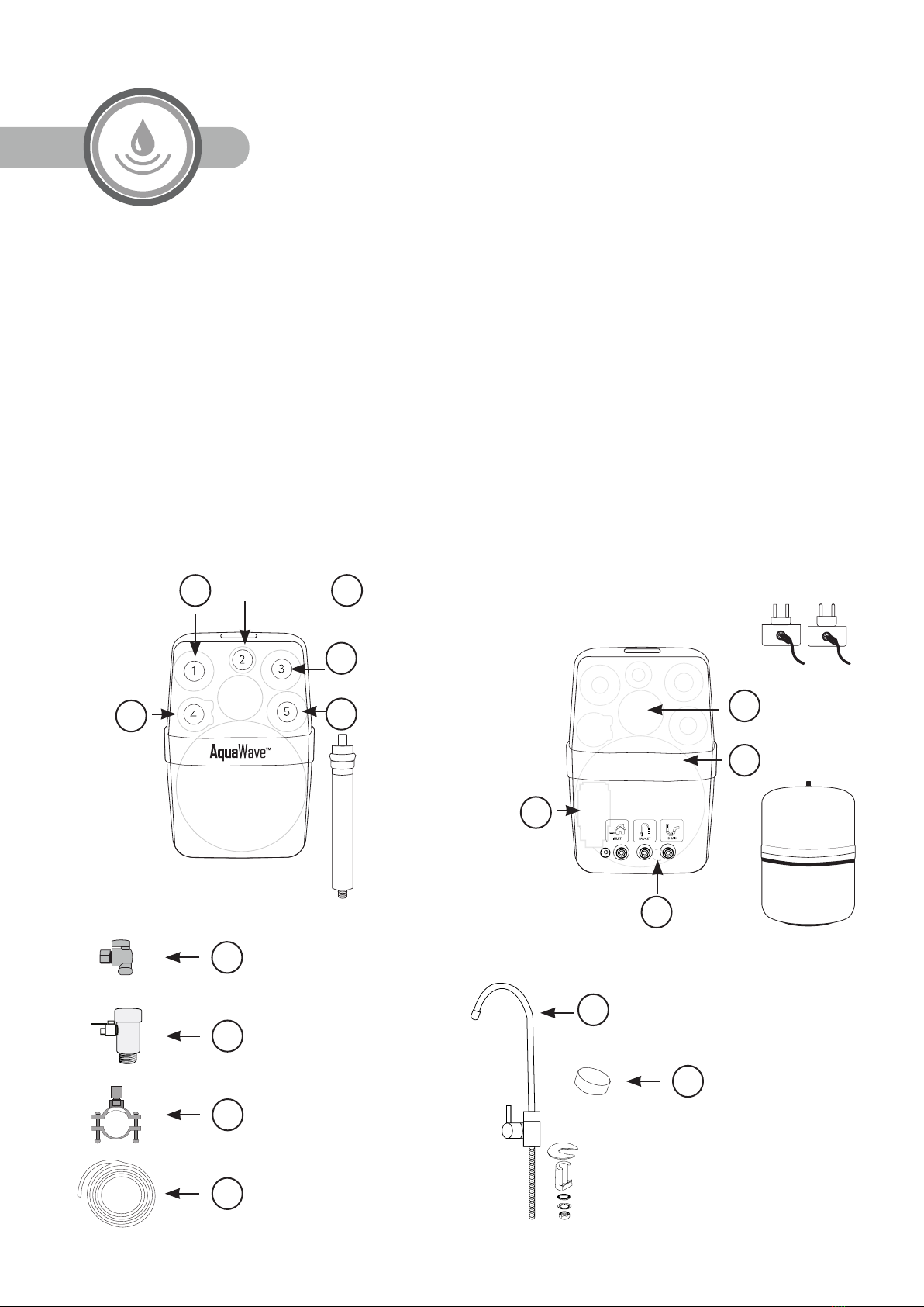
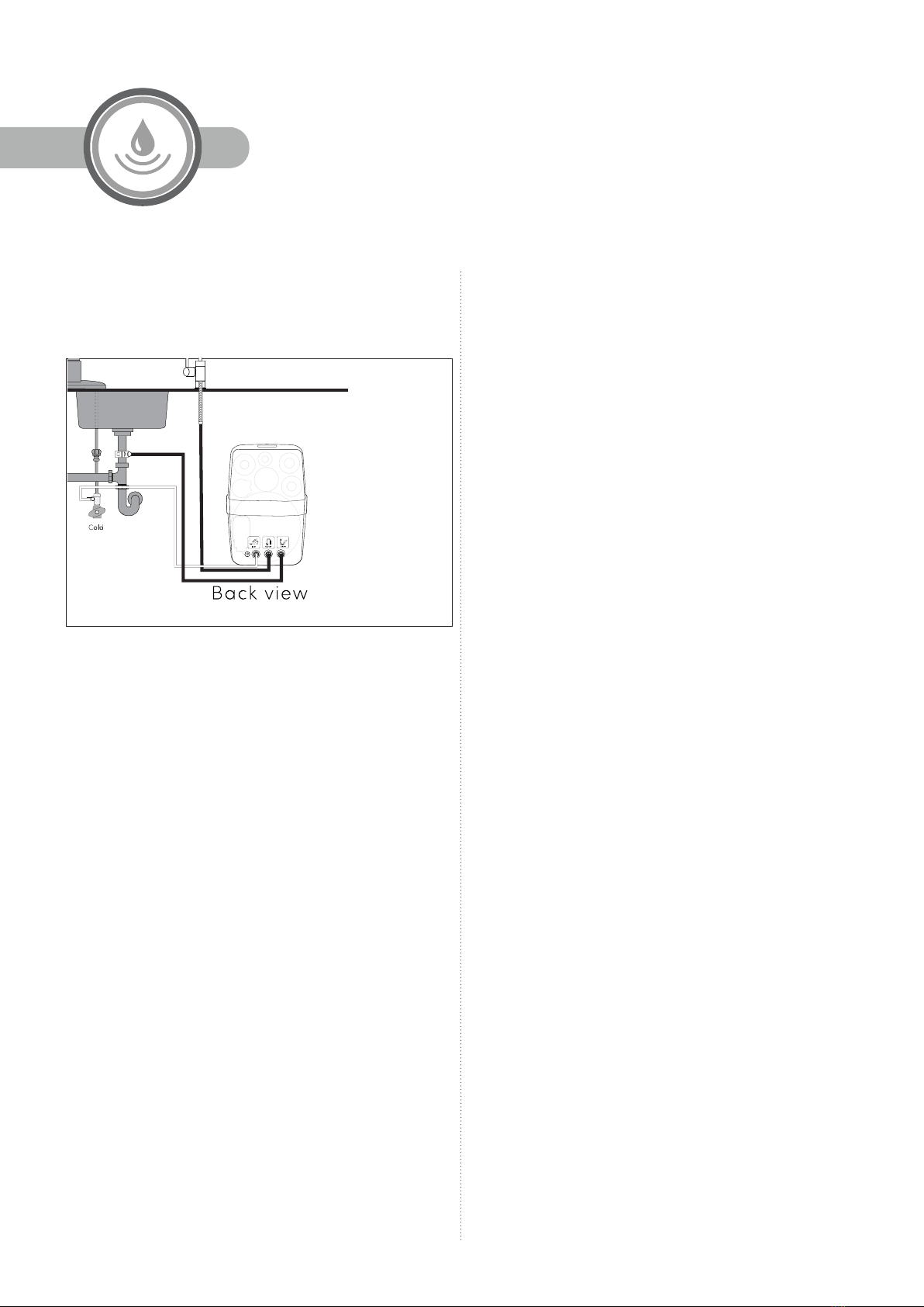
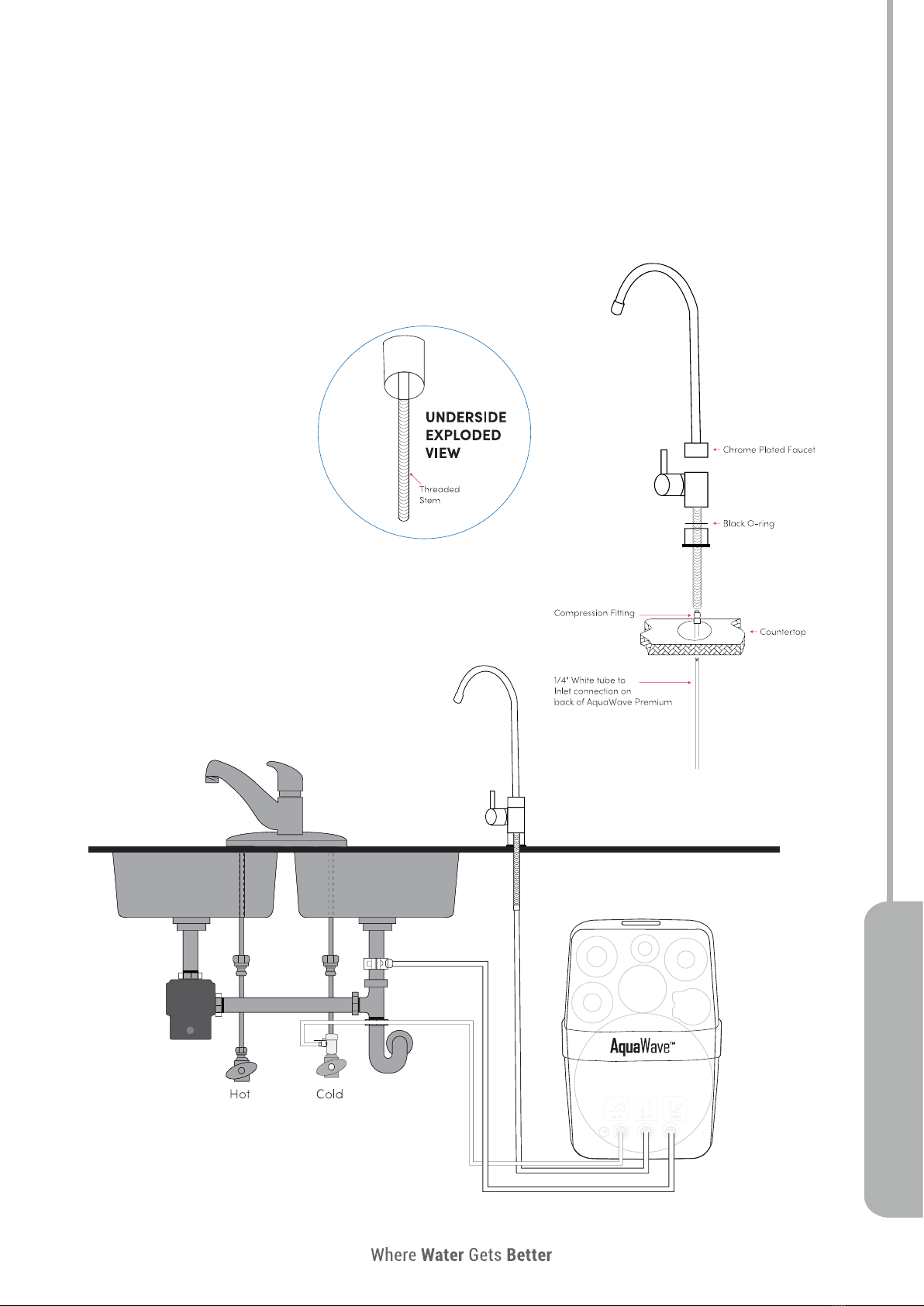
5 Stage Reverse Osmosis System
SPECIFICATIONS
Model AW-PRM-75-38-Q-A
Daily Capacity 75GPD / 280 LPD
Purification Rate up to 96%
Max. Working Pressure 21 - 70psi /1.5 – 5.0bar
Inlet Water Temperature 41° - 100°F / 5° - 38°C
Dimensions and Weight 38 x 38 x 25 cm; 9,1 kg
Pre- and Post-Filters NSF certified for all models
RO Membrane NSF certified 75GPD
Maximum TDS 1000 ppm
Maximum Chlorine 1.0 ppm
PH 6.0~8.5
RO Water Storage Tank NSF certified, 3.2gl /12lt, 6-7psi/ 0.4
bar pre-charge
Water Pump CE certified, 80 - 110psi/ 5 - 7bar
Pump Adaptor CE certified, AC/DC, 24V 1A, 100-
240Vac, 50/60Hz, 0.8A
Electrical Plug Type A (USA)
Pump Flow Rate 0.8 - 1.2 l/min
OTHER IMPORTANT INFORMATION
• Please note that the lifetime of the filters, as well as their replacement interval strongly depends on the inlet water quality, the
amount of water consumed, the sediment and chlorine content, etc.
System should be isolated from water supply and disconnected from power if not used for more than 1 week. If not used for a
period of 1 month or more RO water storage tank should be emptied.
REPLACEMENT FILTERS AND PARTS
• Filters are consumables and are not covered by the warranty.
• Only use GWS approved replacement filters. Product warranty is void if non-GWS approved replacement filters are used.
• Only use GWS approved spare parts. In the case of any failure of the pump, electric adapter or any other replaceable part
of the system, the replacement product must be approved by Global Water Solutions or an authorized GWS distributor.
Product warranty is void if non-GWS approved spare parts are used.
Model AW-PRM-75-38-Q-C
Daily Capacity 75GPD / 280 LPD
Purification Rate up to 96%
Max. Working Pressure 21 - 70psi /1.5 – 5.0bar
Inlet Water Temperature 41° - 100°F / 5° - 38°C
Dimensions and Weight 38 x 38 x 25 cm; 9,1 kg
Pre- and Post-Filters NSF certified for all models
RO Membrane NSF certified 75GPD
Maximum TDS 1000 ppm
Maximum Chlorine 1.0 ppm
PH 6.0~8.5
RO Water Storage Tank NSF certified, 3.2gl /12lt, 6-7psi/ 0.4
bar pre-charge
Water Pump CE certified, 80 - 110psi/ 5 - 7bar
Pump Adaptor CE certified, AC/DC, 24V 1A, 100-
240Vac, 50/60Hz, 0.8A
Electrical Plug Type C (European)
Pump Flow Rate 0.8 - 1.2 l/min