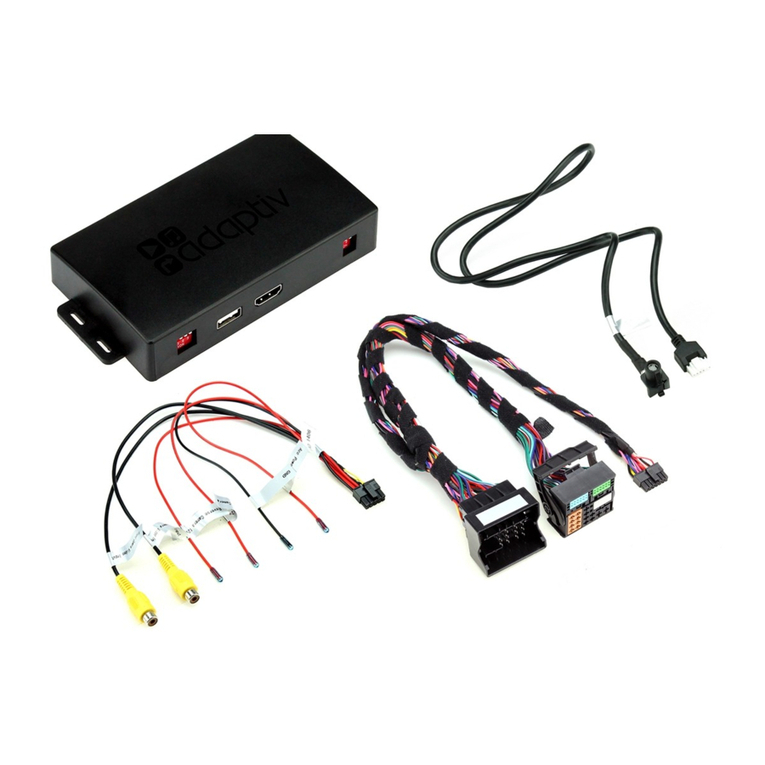
GMC THGMT1 User manual

CABIN MODULE
INSTALLATION GUIDE
GMC
CHEVROLET
CUSTOMER SERVICE
CALL: 800-206-4070 •Mon-Fri 8am - 5pm CST
EMAIL: retrax@retrax.com
4100-032 | 03-2023 l THGMT1

General Service Information 3
Items Required for Installation 4
Installation Order 5
Wiring Diagram (TH) 6
Wiring Diagram for Vehicles with Push-to-Start or Key with OnStar 6
Wiring Diagram for Vehicles with Key, without OnStar 7
Locating Connectors in the Vehicle 8
Wire Chart for Door Trigger 9
Configuring and Flashing the Module 12
Module Programming 13
Entering Pairing Mode on the Cabin Module 14
Pairing Keypad 4100-029 (optional accessory) 15
Diagnostics: Keypad 16
Diagnostics: Cover Module 17
Diagnostics: Parking Lights 18
Troubleshooting 19
Factory Reset: Cabin Module 22
Factory Reset: Cover Module 23
Contents

32015 Chevrolet Silverado 2500/3500
General Service Information
Installation notes to remember:
Always cover fenders, seats, and floor areas before
starting to work.
When working on a vehicle, always roll down a window to
avoid being locked out of the car.
Make all necessary connections (wiring diagram) in the
truck BEFORE plugging in the modules.
Never install the cabin module where it could interfere with
normal operation or obstruct service technicians.
Use caution near airbag wires and connectors as they
are not always labeled (i.e yellow split loom/tubing).
Disconnecting an airbag connector with the ignition turned
on may cause a deployment.
Make sure that all safety equipment (i.e., the hood switch
and the warning label) is installed.
To avoid breaking the plastic fastenings, be gentle when
disassembling the dash and interior panels.
Use extreme caution if the vehicle was parked outside in
very cold weather.

42015 Chevrolet Silverado 2500/3500
Items Required for Installation
Cover module
Cabin Module
Cover Module (installed)
T-Harness

52015 Chevrolet Silverado 2500/3500
Wiring Diagram
Configuring
and Flashing
the Module
Programming
the Cabin
Module
Entering
Pairing Mode Pairing Keypad
Adding accessories (optional)
01
4a 4b
02 03
Installation Order

62015 Chevrolet Silverado 2500/3500
01
Refer to the Locating Connectors in the Vehicle section on the next page for connector locations ( ).
For vehicles equipped with Key without
OnStar, see next page.
3
BCM
(white connector) BCM
(green connector)
BCM
(blue connector)
1
2
BCM
(pink 27-pin conn.)
6
4100-032 (THGMT2)
BCM
(above driver’s kick panel)
1 2 3 4 5 6 7
Pink
27-pin conn.
Brown
26-pin conn.
Black
26-pin conn.
Green
25-pin conn.
Blue
27-pin conn.
White
26-pin conn.
Gray
26-pin conn.
8-Pin White Connector
12-Pin Black Connector
22-Pin White Connector
22 8
12
4 2442
Slide to open
MAIN (5A) (+)
(-) RLY3/PK LIGHT(15A) (+)
5
The brown 5A fuse, which is already
positioned, is the only fuse that
is required for this installatiion.
Loop
BCM
(grey connector)
BCM
(grey connector)
7
7
6
6
Lt. Blue/Black
Connect only
without OnStar*
Wiring diagram 4100-032 (THGMT1)
For vehicles with Push-to-Start (PTS) or Key with OnStar (active or inactive)
Cabin Module
NOT USED

72015 Chevrolet Silverado 2500/3500
01
Refer to the Locating Connectors in the Vehicle section on the next page for connector locations ( ).
3
BCM
(white connector)
BCM
(green connector)
BCM
(blue connector)
1
2
BCM
(pink 27-pin conn.)
6
4100-032 (THGMT2)
BCM
(above driver’s kick panel)
1 2 3 4 5 6 7
Pink
27-pin conn.
Brown
26-pin conn.
Black
26-pin conn.
Green
25-pin conn.
Blue
27-pin conn.
White
26-pin conn.
Gray
26-pin conn.
Refer to the Wire Chart For Door Trigger
section for additional information.
8-Pin White Connector
12-Pin Black Connector
22-Pin White Connector
22 8
12
4 2442
Slide to open
MAIN (5A) (+)
(-) RLY3/PK LIGHT(15A) (+)
5
The brown 5A fuse, which is already
positioned, is the only fuse that
is required for this installatiion.
Loop
BCM
(grey connector)
BCM
(grey connector)
7
7
6
6
Lt. Blue/Black
Connect only
without OnStar*
Wiring diagram 4100-032 (THGMT1) for vehicles with Key, without OnStar
Cabin Module

82015 Chevrolet Silverado 2500/3500
Locating Connectors in the Vehicle

92015 Chevrolet Silverado 2500/3500
Wire Chart for Door Trigger
Vehicles Years Application Instructions Location Pin # Wire Color
GMC Canyon (Key) 2015-2022 WITH power
windows
1) Connect the adapter labeled Connect
only without OnStar.
2) Cut and isolate the loop on the same
adapter.
3) Extend the loose Lt. Blue/Black wire
and run it inside the driver door through
the rubber wiring harness grommet.
4) Make connection with window motor
connector on pin 6 or door latch assembly
pin 1.
Driver window
motor in driver
door
7-pin Black or
Gray/Black
conn. pin 6
Gray
OR (alternate location)
Driver door
latch assembly
in driver door
10-pin Green
conn. pin 1 Gray
Chevrolet Colorado
(Key) 2015-2022 WITH power
windows
1) Connect the adapter labeled Connect
only without OnStar.
2) Cut and isolate the loop on the same
adapter.
3) Extend the loose Lt. Blue/Black wire
and run it inside the driver door through
the rubber wiring harness grommet.
4) Make connection with window motor
connector on pin 6 or door latch assembly
pin 1.
Driver window
motor in driver
door
7-pin Black or
Gray/Black
conn. pin 6
Gray
OR (alternate location)
Driver door
latch assembly
in driver door
10-pin Green
conn. pin 1 Gray
GMC Sierra 1500
(Key) 2014-2021
WITH power
windows
1) Connect the adapter labeled Connect
only without OnStar.
2) Cut and isolate the loop on the same
adapter.
3) Extend the loose Lt. Blue/Black wire
and run it inside the driver door through
the rubber wiring harness grommet.
4) Make connection with window motor
connector on pin 6 or door latch assembly
pin 1.
Driver window
motor in driver
door
7-pin Black or
Gray/Black
conn. pin 6
Gray or Pink
OR (alternate location)
Driver door
latch assembly
10-pin Green
conn. pin 1 Gray or Pink
WITHOUT power
windows
Connect the adapter labeled Connect
only without OnStar.
Note: Do NOT cut the loop and do NOT
connect the Lt. Blue/Black wire.
BCM
26-pin Grey
conn. (7)
pin 25
Gray or Pink
GMC Sierra 1500
Limited (Key) 2019/2022
WITH power
windows
1) Connect the adapter labeled Connect
only without OnStar.
2) Cut and isolate the loop on the same
adapter.
3) Extend the loose Lt. Blue/Black wire
and run it inside the driver door through
the rubber wiring harness grommet.
4) Make connection with window motor
connector on pin 6 or door latch assembly
pin 1.
Driver window
motor in driver
door
7-pin Black or
Gray/Black
conn. pin 6
Gray or Pink
OR (alternate location)
Driver door
latch assembly
10-pin Green
conn. pin 1 Gray or Pink
WITHOUT power
windows
Connect the adapter labeled Connect
only without OnStar.
Note: Do NOT cut the loop and do NOT
connect the Lt. Blue/Black wire.
BCM
26-pin Grey
conn. (7)
pin 25
Gray or Pink

10 2015 Chevrolet Silverado 2500/3500
Wire Chart for Door Trigger
Vehicles Years Application Instructions Location Pin # Wire Color
GMC Sierra 2500HD
(Key) 2015-2023
WITH power
windows
1) Connect the adapter labeled Connect
only without OnStar.
2) Cut and isolate the loop on the same
adapter.
3) Extend the loose Lt. Blue/Black wire
and run it inside the driver door through
the rubber wiring harness grommet.
4) Make connection with window motor
connector on pin 6 or door latch assembly
pin 1.
Driver window
motor in driver
door
7-pin Black or
Gray/Black
conn. pin 6
Gray or Pink
OR (alternate location)
Driver door
latch assembly 10-pin Green
conn. pin 1 Gray or Pink
WITHOUT power
windows
Connect the adapter labeled Connect
only without OnStar.
Note: Do NOT cut the loop and do NOT
connect the Lt. Blue/Black wire.
BCM
26-pin Grey
conn. (7)
pin 25
Gray or Pink
GMC Sierra 3500HD
(Key) 2015-2023
WITH power
windows
1) Connect the adapter labeled Connect
only without OnStar.
2) Cut and isolate the loop on the same
adapter.
3) Extend the loose Lt. Blue/Black wire
and run it inside the driver door through
the rubber wiring harness grommet.
4) Make connection with window motor
connector on pin 6 or door latch assembly
pin 1.
Driver window
motor in driver
door
7-pin Black or
Gray/Black
conn. pin 6
Gray or Pink
OR (alternate location)
Driver door
latch assembly
in driver door
10-pin Green
conn. pin 1 Gray or Pink
WITHOUT power
windows
Connect the adapter labeled Connect
only without OnStar.Note: Do NOT cut BCM 26-pin Grey
conn. (7) Gray or Pink
Chevrolet Silverado
1500 (Key) 2014-2021
WITH power
windows
1) Connect the adapter labeled Connect
only without OnStar.
2) Cut and isolate the loop on the same
adapter.
3) Extend the loose Lt. Blue/Black wire
and run it inside the driver door through
the rubber wiring harness grommet.
4) Make connection with window motor
connector on pin 6 or door latch assembly
pin 1.
Driver window
motor in driver
door
7-pin Black or
Gray/Black
conn. pin 6
Gray or Pink
OR (alternate location)
Driver door
latch assembly
10-pin Green
conn. pin 1 Gray or Pink
WITHOUT power
windows
Connect the adapter labeled Connect
only without OnStar.
Note: Do NOT cut the loop and do NOT
connect the Lt. Blue/Black wire.
BCM
26-pin Grey
conn. (7)
pin 25
Gray or Pink
Chevrolet Silverado
LD (Key) 2019
WITH power
windows
1) Connect the adapter labeled Connect
only without OnStar.
2) Cut and isolate the loop on the same
adapter.
3) Extend the loose Lt. Blue/Black wire
and run it inside the driver door through
the rubber wiring harness grommet.
4) Make connection with window motor
connector on pin 6 or door latch assembly
pin 1.
Driver window
motor in driver
door
7-pin Black or
Gray/Black
conn. pin 6
Gray
OR (alternate location)
Driver door
latch assembly 10-pin Green
conn. pin 1 Gray
WITHOUT power
windows
Connect the adapter labeled Connect
only without OnStar.
Note: Do NOT cut the loop and do NOT
connect the Lt. Blue/Black wire.
BCM
26-pin Grey
conn.(7) pin
25
Gray

11 2015 Chevrolet Silverado 2500/3500
Wire Chart for Door Trigger
Vehicles Years Application Instructions Location Pin # Wire Color
Chevrolet Silverado
1500 LTD (Key) 2022
WITH power
windows
1) Connect the adapter labeled Connect
only without OnStar.
2) Cut and isolate the loop on the same
adapter.
3) Extend the loose Lt. Blue/Black wire
and run it inside the driver door through
the rubber wiring harness grommet.
4) Make connection with window motor
connector on pin 6 or door latch assembly
pin 1.
Driver window
motor in driver
door
7-pin Black or
Gray/Black
conn. pin 6
Gray or Pink
OR (alternate location)
Driver door
latch assembly
in driver door
10-pin Green
conn. pin 1 Gray or Pink
WITHOUT power
windows
Connect the adapter labeled Connect
only without OnStar.
Note: Do NOT cut the loop and do NOT
connect the Lt. Blue/Black wire.
BCM
26-pin Grey
conn. (7)
pin 25
Gray or Pink
Chevrolet Silverado
2500HD (Key) 2015-2023
WITH power
windows
1) Connect the adapter labeled Connect
only without OnStar.
2) Cut and isolate the loop on the same
adapter.
3) Extend the loose Lt. Blue/Black wire
and run it inside the driver door through
the rubber wiring harness grommet.
4) Make connection with window motor
connector on pin 6 or door latch assembly
pin 1.
Driver window
motor in driver
door
7-pin Black or
Gray/Black
conn. pin 6
Gray or Pink
OR (alternate location)
Driver door
latch assembly
10-pin Green
conn. pin 1 Gray or Pink
WITHOUT power
windows
Connect the adapter labeled Connect
only without OnStar.
Note: Do NOT cut the loop and do NOT
connect the Lt. Blue/Black wire.
BCM
26-pin Grey
conn. (7)
pin 25
Gray or Pink
Chevrolet Silverado
3500HD (Key) 2015-2023
WITH power
windows
1) Connect the adapter labeled Connect
only without OnStar.
2) Cut and isolate the loop on the same
adapter.
3) Extend the loose Lt. Blue/Black wire
and run it inside the driver door through
the rubber wiring harness grommet.
4) Make connection with window motor
connector on pin 6 or door latch assembly
pin 1.
Driver window
motor in driver
door
7-pin Black or
Gray/Black
conn. pin 6
Gray or Pink
OR (alternate location)
Driver door
latch assembly
10-pin Green
conn. pin 1 Gray or Pink
WITHOUT power
windows
Connect the adapter labeled Connect
only without OnStar.
Note: Do NOT cut the loop and do NOT
connect the Lt. Blue/Black wire.
BCM
26-pin Grey
conn. (7)
pin 25
Gray or Pink

12 2015 Chevrolet Silverado 2500/3500
To configure and flash your module, follow the prompts on the REALTRUCK
app from your mobile device.
Configuring and Flashing the Module
02
Google Play and the Google Play logo are trademarks of Google LLC.

13 2015 Chevrolet Silverado 2500/3500
Make sure you have configured and flashed the module
before proceeding with this section.
You have successfully programmed the cabin module.
Programming the Cabin Module
03
Ensure vehicle is in a safe location and cannot move forward during programming.
Turn the ignition to the ON position and wait for the LED to turn on solid orange and then turn o.
Turn the ignition o.
P
1
2
3
START
Key OUT
ON
OFF
STA R T
Key IN
ON
OFF
Solid O
Attention!

14 2015 Chevrolet Silverado 2500/3500
Entering Pairing Mode on the Cabin Module
This section is only required if pairing additional accessories such as keypads, cell phones, etc.
Make sure the cabin module is programmed before proceeding with the pairing of the cover
module and optional keypad.
Review all of the steps below before starting
as the pairing sequence is time sensitive.
Important! You must be next to your vehicle
with all doors closed to begin the pairing
sequence.
Turn the ignition o.
Press and release the brake pedal.
Make sure all doors are closed, and then
unlock and open the driver’s door.
Note: A 30-second timer begins as soon as
you open the door.
Press and release the brake pedal three times
(3x).
Turn the ignition on, without pressing the
brake pedal.
Turn the ignition on.
You have successfully entered Pairing Mode.
You have one minute to pair a keypad, cell phone, or any other accessory to the cabin module.
4a
Optional!
1
5
7
2
43
6
8
START
Key OUT
ON
OFF
START
Key IN
ON
OFF
START
Key IN
ON
OFF
Important!

15 2015 Chevrolet Silverado 2500/3500
Pairing keypad 4100-029 (optional accessory)
If you have purchased the keypad, follow the instructions below to pair it to the cabin module.
Enter Pairing Mode by following the steps on
the previous page.
Important! You must complete Steps 2-4
within one minute.
Enter the master code that is behind the
keypad.
When the master code is successfully entered,
the backlight and green LED will flash slowly.
Press and hold the 1/2, 3/4, and 9/0 buttons
simultaneously until the orange backlight LEDs
flash rapidly.
Within 20 seconds, press and hold the 5/6
button until the backlight LED flashes rapidly
and the cabin module unlocks the vehicle,
confirming pairing has been successful.
Note: If pairing fails, wait for the LEDs to turn
o. Then, repeat Steps 2 and 3, and at
Step 4, press and hold 7/8 until the LED flashes
rapidly. Finally, you can repeat Steps 1-4.
For more information about the keypad and its features, refer to the Owner’s Guide.
4b
1
3
2
4
Note: The master code will be the default pin and cannot be deleted.
1
4
3
6
5
8
9 0
7
2
1
4
3
6
5
8
9 0
7
21
4
3
6
5
8
9 0
7
2

16 2015 Chevrolet Silverado 2500/3500
Keypad LED Behavior
Action LED
Pressing any button in locked mode
• Green flashes 1x as button is pressed
• The backlight will light up to 5 seconds on a key press
• If no other button is pressed within 5 seconds, the keypad
will time out and the backlight LED will turn o
Passcode successful
• Backlight solid on for 10 seconds
• Green LED flashes slowly 3x
Entering the passcode incorrectly 3x
(Anti-Scan mode)
Note: The keypad will be disabled for 60s.
Backlight and green LED flash rapidly 3x and then turn o
Programming second personal code
(entering Configure mode) Backlight LED flashes rapidly 3x

17 2015 Chevrolet Silverado 2500/3500
Cover Module LED Diagnostics
LED Pattern Description Meaning/Reasons
Solid ON Power source is connected
• The cover module can be detected by the
RealTruck app
• The cover module is in Factory Reset mode
• Cover module is not paired yet
Note: The LED will turn o when the cover
module has been paired to the cabin module
OFF The cover module has a
paired cabin module
Power source is connected, and the paired cabin
module is detected
OR
Cover module has no power
LED turns ON for 3 seconds,
then OFF
The paired cabin module
is nearby
To verify if the cover module is powered up and
paired to the cabin module, press and release
the cover module button. The LED will turn on for
three seconds, then turn o.
Flash 1x every 2 seconds
for two minutes
The cover module is searching
for the cabin module
When the 12V power source is connected, the
cover module scans for the cabin module, but
there is no communication between the modules.
Flash 2x
The cover module is unable to
find its paired cabin module
(Paired Alone state)
Cover module scanning for the cabin module has
timed out.
• Solution 1: Cycle power to the cabin module
• Solution 2: To pair a new cabin module,
perform a factory reset on the cover module
Flashes 5x repeatedly The cover module has entered
Factory Reset mode
The installer has done the following sequence
on the cover module:
Press → release → press → release →
press and hold for 2 seconds
The installer has 15 seconds to confirm factory
reset. Once the 15 seconds has elapsed, the
cover module goes back to flashing 2x (Paired
Alone state)

18 2015 Chevrolet Silverado 2500/3500
Vehicle Parking Lights Diagnostics (if applicable)
Number of Flashes Description Meaning/Reasons
3x
The cabin module has lost
communication with the
cover module
The cover module has lost power, or interference
has caused a loss of communication
4x
• An obstruction is preventing the
cover from opening or closing
• Motor failed to engage to move
• The cover module detected an obstruction
while the bedcover is moving
• Connection issue between the cover module
harness and motor
6x System detected an out-of-range
temperature or voltage reading
• The maximum operating temperature (above
185F/85C) has exceeded.
• The vehicle’s battery voltage is below 9.5V
1x every 2 seconds
(if applicable)
The cabin module entered
Pairing Mode
Flashing indicates cabin module is ready and
scanning to pair any additional accessories

19 2015 Chevrolet Silverado 2500/3500
Troubleshooting
RealTruck App Detection Issues: Setting up a new system
Problem:
The cabin module ID does not appear in the RealTruck app
Cause No power source is connected.
Solution Make sure the 12-pin black connector (power source) is properly connected to the
cabin module.
Cause The app scanning feature for the cabin module has timed out.
Solution
• Refresh the page by pulling down at the center of the display or tap on the
recycle/refresh arrow to start scanning again.
• Disconnect the 12-pin black connector and reconnect it.
The blue LED will turn on for 1 second, then o, then turn on and stay yellow (or
turn o after 3 seconds).
Cause The 12-pin black connector is connected but the cabin module’s LED does not light up.
Solution Using a voltmeter, verify that the cabin module has power (red wire) and ground (black
wire) on the 12-pin connector.
Problem:
The cover module ID does not appear in the RealTruck app
Cause Power connector is not connected.
Solution
Plug the 2-pin power connector properly to the cover module. Using a voltmeter,
verify that the cabin module has power and ground on the red and black wire on
2-pin connector.
Cause The app scanning feature for the cover module has timed out.
Solution Refresh the page by pulling down at the center of the display or tap on the recycle
arrow to start scanning again. The cover module ID will now be displayed.
Important!
The cabin module will time out after 20 mins of being idle.
Disconnecting and reconnecting the cabin module will reset the timer. For the RealTruck app to detect
either the cabin module or cover module, the cover module’s LED must be solid ON while the cabin
module’s LED must be solid yellow.

20 2015 Chevrolet Silverado 2500/3500
Problem:
The cover module ID shows up on the RealTruck app, but the selection is in red background
Cause The cover module was previously paired with a cabin module.
Solution
Perform a factory reset (see the Factory Reset: Cover Module section).
Indication that the cover module can be set to Factory reset mode: LED flashes 2x.
Troubleshooting
Problem:
The cabin module does not enter Pairing Mode
Cause Only the 12-pin black connector is connected.
Solution Make sure all necessary connectors are properly connected on the cabin module
and to the vehicle.
Cause Cabin module programming was not performed properly.
Solution Make sure that the cabin module is programmed (the LED should not be solid ON).
Pairing Issues
The cabin module must be programmed first to the vehicle,
after all connections have been done.
See the Programming the Cabin Module section.
?
Table of contents
Other GMC Automobile Electronic manuals
Popular Automobile Electronic manuals by other brands

peitel
peitel PTCarPhone 4 Brief Instruction

Eplus
Eplus P436.CE Assembly manual

Mid City Engineering
Mid City Engineering SmartKey Starter SKSNG166D4T installation manual

Westfalia Automotive
Westfalia Automotive Autocode-Mini Getting started guide

CrimeStopper
CrimeStopper SecurView SV-6910 installation manual

Code 3
Code 3 SuperVisor Installation & operation manual