GM
COACH
MAINTENANCE MANUAL
Page
5
INDEX
A
Page
Accessories,
Engine
• • • • • • • • • • • • • • • • • 142
Adjustments
Bearings,
Wheel
•••••••••••••••••••
Brake
Application
Valve
••.••••••••••
Brake Shoe
....................
.
Brake
Treadle
Clutch
.........................
.
Compressor
Unloader
Valve
•••••••••••
Drag
Link,
Steering
• • • • • • • • • • • •
•••
Fog
Lights . . . . . . . . . . . . . . . . .
.....
Generator
Neutral
Point
•••••.•••••••
Governor,
Air
Compressor
•••••••••••
Hand Brake
....................
.
Headlights
......................
.
Pressure
Regulating
Valve
•••••••••••
Regulator,
Generator
•••••••••••••••
Relays
........................
.
Safety
Valve
•••••••••••••••••••••
Steering
Gear
• • • • • • • • • • • • • • • •
••••
Stop
Screw,
Steering
Knuckle
•••••••••
Tie
Rod
........................
.
Windshield
Wiper
Valve
•••••••••••••
Air
Brakes
•••••••••••••••••••••••
Air
Cleaners,
Engine
••••••••••••••••
Air
Compressor
and
Governor
•••••••••
Air
Horns
.......................
.
Air
Intake
System,
Engine
• • • • • • • • • • • • •
Alarm
System,
Tell-tale
•••••••••••••
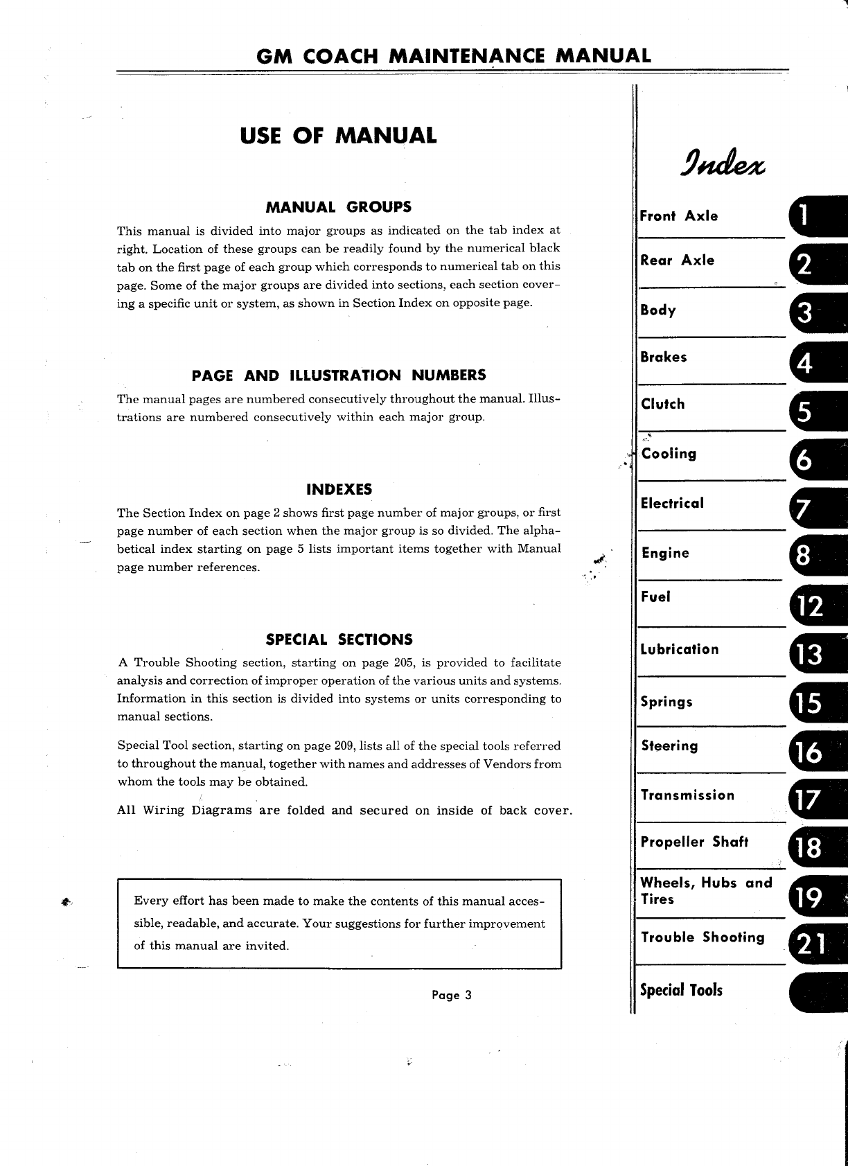
Alignment,
Front
End
• • • •
••••••••••••
Antifreeze
Chart
..................
.
Application
Valve,
Brake
•••••••••••••
Axle, Front
......................
.
Axle,
Rear
......................
.
B
199
51
44
44
179
71
177
134
125
71
75
133
48
128
109
45
171
10
10
38
43
151
63
38
150
107
7
98
48
7
17
Battery
• • • • • • • • • • • • • • • • • • • • • • • • • •
115
Battery
Junctions
••••••••••••••••••
, 106
Bearings,
Wheel
• • • • • • • • • • • . • • • • • • • 199
Body
• • • . • • • • • • • • • • • • • • • • • • • • • • . • 29
Body
Junction
Panel
• • • • • • • • • • • • • • • • • 104
Brake
Chambers
• • • • • • • • • • • . • • • • • • •
55
Brake
Drums
• • • • • • • • • • • • • • • • • • • • •
61
Brake,
Hand • • • • • • • • • • • • • • • • • • • • • • 75
Brakes,
Air . . . . . . . . . . . . . . . . . . . . . . . 43
Buzzer,
Tell-tale
Alarm
• • • • • • • • • • • • • • 107
C
Capacity,
Cooling
System
•••••.•••••••
Check
Valve,
Aux.
Air
System
•.•••••••
Check
Valve,
Compressor
Discharge
••••••
Chime,
Passenger
Signal
•••••••••••••
Circuit
Breaker
Panel
•••••••••••••••
Clutch
Compressor,
Air
. .
.....
Cl
• •
•••••••••
<;ontrol
Panel,
Driver's
••••••••••••••
Cooling
System
. . . . .
..............
.
98
48
46
39
102
179'""'
63
101
89
D
Page
Diesel
Engine
• • • • • • • • • • • • • • • • • • • • • 141
Doors
and
Controls
• • • • • • • • • • • • • • • • • 35
Drag
Link,
Steering
• • • • • • • • • • • • • • • • • 177
E
Electrical
System
•••••••••••••••••••
Electric
Horn
Emergency
Door
..................
.
Engine
Comp't.
Panel
•••••••••••••••
Engine
Mounting
•••••••••••••••••••
Engine
Tune-up
••••••••••••••••••.•
Entrance Door
.......
If
• • • • •
••••••••
F
Fan
and
Water
Pump
••••••••••••••••
Filter,
Fuel
Oil
.••••••••••••••••••
Filter,
Lubricating
Oil
• • • • • • • • • • • •
•••
Front
Axle
•••••••••••••••••••••••
Fuel
Oil
Specifications
•••••••••••••••
Fuel
System
••••••••••••••••••••••
Gauge,
Air
Pressure
Gauge,
Oil
Pressure
G
Gauge
Panel
.....................
.
Generator
.......................
.
Generator
Regulator
•••••••••••••••••
Glass
Replacement
••••••••••••••••••
Governor,
Air
Compressor
••••••••••••
H
Hand
Brake
Heating
.........................
.
Horn,
Electric
•••••••••••••••••••••
Horns,
Air
•••••••••••••••••••••••
Hubs
and
Bearings
• • • • • • • • • • • • • • • • •
99
113
35
105
145
141
35
97
149
143
7
154
149
46
142
100
121
126
36
71
75
39
113
38
199
Injector
Shut-off,
.Air
Operated
• • • • • • • • • 144
L
Lighting
System
••••.•••••••••••••••
Lights,
Tell-tale
.••••••••••••••••••
Links,
Shock
Absorber
•••••••••••••••
Low
Air
Pressure
Switch
•••••••••••••
Lubrication
Lubrication
Chart
M
Mato-Gard
........
"
..............
.
132
107
168
46
155
156
108
I


 Operator's manual")